University of New Orleans University of New Orleans
ScholarWorks@UNO
ScholarWorks@UNO
University of New Orleans Theses and
Dissertations Dissertations and Theses
Fall 12-20-2018
Feasible Form Parameter Design of Complex Ship Hull Form
Feasible Form Parameter Design of Complex Ship Hull Form
Geometry
Geometry
Thomas L. McCulloch
University of New Orleans, [email protected]
Follow this and additional works at: https://scholarworks.uno.edu/td
Part of the Artificial Intelligence and Robotics Commons, Computer-Aided Engineering and Design Commons, Graphics and Human Computer Interfaces Commons, Numerical Analysis and Scientific Computing Commons, Ocean Engineering Commons, and the Software Engineering Commons
Recommended Citation Recommended Citation
McCulloch, Thomas L., "Feasible Form Parameter Design of Complex Ship Hull Form Geometry" (2018). University of New Orleans Theses and Dissertations. 2552.
https://scholarworks.uno.edu/td/2552
This Dissertation is protected by copyright and/or related rights. It has been brought to you by ScholarWorks@UNO with permission from the rights-holder(s). You are free to use this Dissertation in any way that is permitted by the copyright and related rights legislation that applies to your use. For other uses you need to obtain permission from the rights-holder(s) directly, unless additional rights are indicated by a Creative Commons license in the record and/ or on the work itself.
Feasible Form Parameter Design of Complex Ship Hull Form Geometry
A Dissertation
Submitted to the Graduate Faculty of the University of New Orleans in partial fulfillment of the requirements for the degree of
Doctor of Philosophy in
Engineering and Applied Science Naval Architecture & Marine Engineering
by
Thomas Luke McCulloch B.S. Auburn University, 2004 MBA Auburn University, 2007 M.S. University of New Orleans, 2010
c
2018, Thomas Luke McCulloch
Acknowledgments
The privilege of writing a dissertation would not be possible without the help of so many people.
First and foremost, the advisors. Lothar, thank you for guiding me along this journey by suggesting some excellent problems and guiding me back where I might have sailed too far off the path. Baker, I really lucked out to find you down the road at LSU Lafayette. You knew exactly what I needed to hear and at just the right time. Dr. Vorus, thanks for giving me a chance to “work on the hard problems” way back in the beginning of my time in engineering grad-school.
Will Byrd, thank you for giving me some of your time to talk intervals in and around miniKanren. Thanks, Chris McKesson, for being so welcoming after I had been away. ThanksotherBaker, you showed me how its done, and Chase for all the fun discussions in the grad office. Thanks Ryan, for years of good jokes and lots of fun messing with gear in the wave tank. We still need to attempt a jam session. Maybe I’ve got time now. Thanks George, for years of bad jokes and lots of fun messing with stuff in the wave tank too.
Thank you everyone atNOLA Hack Nightand theNOFUN’ctors of NOLA. (Thanks to you guys for letting me get up and talk about engineering and... Python! You always made me feel welcome.) Thanks especially to Hunter for introducing me around, and letting me drink beers in your sweet floating geodesic dome during bayou boogaloo. If anybody actually reads this, you could do worse than moving to New Orleans for your PhD.
Thanks very much,Bentley Systems, for giving me some free time to work on this. Thanks particularly to the guys in theSACSoffice, for putting up with my comings and goings, and to Phil Christensen, for taking me on in the first place.
Contents
List of Figures . . . vii
List of Tables . . . xi
List of Listings . . . xii
Abstract . . . xv
1 Introduction . . . 1
2 Related Work . . . 11
3 Form Parameter Design of Ship Hull Geometry . . . 36
3.1 Introduction and Greater Context . . . 36
3.2 Procedures . . . 38
3.3 Hull Form Generation . . . 39
3.4 Curves of Form . . . 40
3.5 Transverse Curves . . . 49
3.6 Longitudinal Curves . . . 51
3.7 Summary . . . 54
4 Lagrangian Curve Design of B-splines . . . 55
4.1 Constraints . . . 57
4.2 Objective Function . . . 60
5 Automatic Differentiation Scheme . . . 65
5.1 B-spline Evaluation Example . . . 70
6 Automatic Differentiation of B-splines . . . 75
7 B-spline Curve Design Examples . . . 78
7.1 SAC Design and Optimization . . . 79
7.2 Design of a Stern Profile Curve . . . 82
7.3 Finding a Fair Enclosure . . . 85
7.4 Summary . . . 87
8 Picking Feasible Form Parameters . . . 88
8.1 Interval Analysis . . . 90
8.2 Constraint Logic Programming Scheme . . . 117
9 An Internal Domain Specific Language for Constraint Propagation . . . 155
9.1 Implementation: Compiling Logical Rules . . . 157
10 Truncated Hierarchical B-splines . . . 172
10.1 Introduction to Multiresolution Modeling . . . 172
10.2 Choosing a Representation And THB-spline Theory and Implementation . . . 175
10.3 Important Properties Satisfied by THB-splines . . . 184
10.4 Multilevel Editing . . . 184
10.5 Multilevel Optimization . . . 187
11 Final Program . . . 195
11.1 Random Form Parameter Input Generation . . . 196
11.2 Complex Hull Form With Bulbous Bow . . . 201
11.3 Usage of THB splines to Assemble the Complex Hull . . . 206
12 Results . . . 218
12.1 Plots of Generated OSV Hull Geometry . . . 218
12.2 Validation by Tables of Results . . . 246
13 Summary and Conclusions . . . 253
13.1 Future Work and Outlook . . . 255
Bibliography . . . 261
List of Figures
1.1 From Abt and Harries, [1], Cost vs. Time, top, and Knowledge vs. Time, bottom. This represents the knowledge gap. Expenses fixed by design decisions become large shortly after a project commences, but the knowledge accumulated is at a minimum here. Therefore, we strive to increase the amount of knowledge early on in the design phase, and so close the gap. . . 2 3.1 Bare hull form generation process workflow for feasible form parameter design . . . 38 3.2 FPD Process Example: Using SAC to specify area at hull stations. Figure from Birk, [2]. . . . 40 3.3 Normalized Sectional Area Curve Showing flat mid-section and fore and aft transverse area
accommodations for the eventual bulbous bow and transom stern. Longitudinal center of gravity is also fixed in this curve, though not shown here. See section 7.1 for more details on SAC optimization. An overview of the form parameters used for this particular curve, and thus those used in the eventual hull forms developed here, is given below in table 3.2. . . 42 3.4 Normalized Sectional Area Curve Also showing concurrently designed Bulbous Bow Sectional
Area Curve and fairing area (small curve to bottom left, where the flat portion is actual bulbous bow and the angled portion handles fairing from the bulbous bow to the hull proper). Furthermore, the bulbous bow itself is the flat section of the smaller curve, while the inclined section shows that the fairing of the bulb into the hull will show an increasing sectional area moving aft. Note that fairing curve can be influenced by rule. This will be important later in the thesis for “nicely” integrating the complex hull. . . 43 3.5 Normalized Designed Waterline Curve. . . 46 3.6 Normalized Center-plane Keel Profile Curve. Forward sweep developed (at bow, left) in
anticipation of the addition of the bulbous bow. Transom “drop” aft is controlled byyE. . . 48
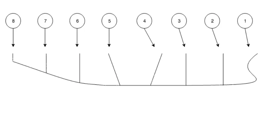
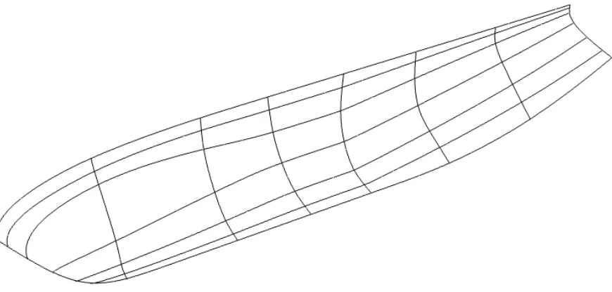
3.7 Normalized primary SAC, bulbous bow and blending section SAC, and a designed waterline and center plane keel profile curve. The bulbous bow SAC is the short curve visible at bottom left. The fairing area is shown as well, though hard to discern here. The full length curves at bottom are the design waterline and center plane keel. Note that the design waterline (half breadth) and center plane keel have similar magnitude of maximum depth and magnitude of maximum width on this vessel. We might use a draft to beam rule if we wish to control this. . 50 3.8 Simple transverse curves network. This view shows the longitudinal positioning of these curves.
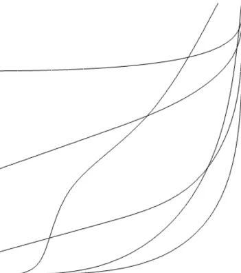
Bow curve at far right. Transom curve at far left. An initial bow curve is shown. It will be replaced when the form parameter designed bulbous bow is added. . . 51 3.9 Transverse section curves. . . 52 3.10 Simple (bare hull) Longitudinal Curves. This is what a set of bare hull curves would look like
without modifications to support bulbous bow incorporation. . . 53 3.11 Simple (bare hull) Longitudinal Curves. Note that the form parameter designed bulbous bow
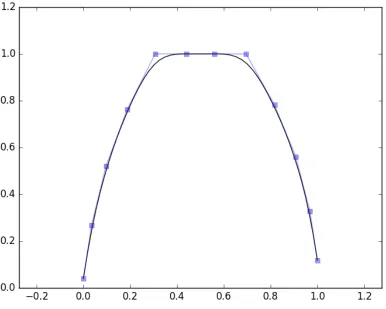
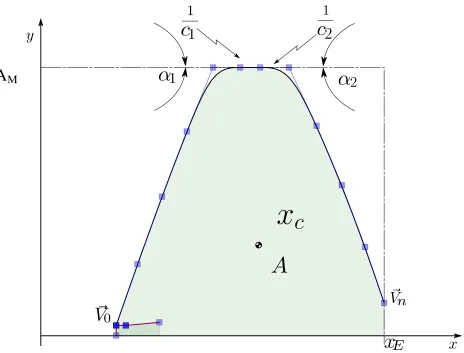
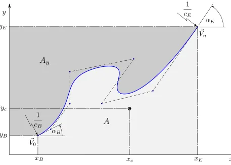
4.1 Desired curve properties defined by a selection of form parameters . . . 56 7.1 initial SAC curve . . . 79 7.2 SAC curve development . . . 80 7.3 Run Profile (This is a single B-spline curve). Note the relative constraints,r1,r2, andr3, as
well as the particular cusps,k1andk2, which enforce user chosen geometry while allowing the local assembly to remain free to move relative to the rest of the control points. . . 83 7.4 curve enclosing a box . . . 85 8.1 Annotated computational syntax tree for the constraint: (x1+x2)×x3 ∈ [1.,2.]In our
program, we will use Python’s native parsing plus operator overloading to produce such trees automatically from mathematical input. . . 102 8.2 Creation of intermediate terms,aandb, which will allow interval values to propagate up the
syntax tree. . . 103 8.3 Forward propagation. The algorithm carries out the basic computations of the rule, contracting
the interval widths where possible. . . 104 8.4 Annotation tree for the backward propagation of the constraint. Dummy variables again aid in
propagating data — this time back down the tree to the terminal interval nodes,x1,x2,x3. . . 105 9.1 Example Computational Graph Using Naval Architecture Rules. Ellipses represent design
variables which have not yet been used by the designer as explicit rules. Boxes represent those form parameters which have. (Any mathematically defined term is also a rule. Computationally, if only for graphing purposes, we distinguish here between those that have appeared on the left hand side of our relational equality “double equals sign” and those that have not yet done so.) Lines represent paths of mutual dependence between form parameters. Self intersecting lines represent relations that also define design variables. . . 163 9.2 Code transformation procedure enacted by thePStatesclass under composition to form
compound mathematical relationships and transform them into relational, logical rules. . . 170 10.1 Multilevel THB refined Bare Hull before deformation. Transverse curves shown in orange.
(Displayed in Python’s Matplotlib library becauseRhinodoes not support hierarchical splines, but only allows T-splines which we excluded from consideration in section 10.2 ) . . . 185 10.2 Mulitlevel THB Hull after Bulbous Bow deformation with THB-spline refined control vertex net.
Higher vertex counts denoted by blue circles denoting vertices at one higher level of refinement as compared to the magenta vertices aft. Please note that this single surface THB-spline will be refined further, especially the forward surface portions, and then projected to a B-spline representation at the highest level of detail and sent to Rhino for final display. See below for details and example hulls which have been further processed in this way. . . 187 10.3 Adaptively refined and solved longitudinal curves. Here, portions of the longitudinal space
curves forward of midship have been refined. . . 188 10.4 THB-spline curve optimization algorithm flowchart . . . 191 11.1 Final output of the form parameter process: A multi-surface complex hull. . . 195 11.2 Basic algorithm using arc consistency for random, yet consistent, form parameter design
11.4 Forward Fairness Curve: shown here, in gold (or lighter color if viewing in black and white). The relative longitudinal position of this curve is a “hyperparameter” of the program, as are the relative forward position (from bow to midships sections) of the other forward volume defining curve and the relative aft positions (from midships sections to stern) of the aft volume defining curves. The area of this particular curve, as with any transverse station curve, is derived from SAC. The following information sets this curve apart from other fore and aft volume curves: The fraction of this curve’s area which is contained in the lower “bulbous” or here, simply rounded, portion of this curve is another input to the system which can be chosen by the user. Since it will be known in advance, it is used to set the height of the bulbous bow fairing sectional area curve at this station. This is an additional curve which shows the volumetric distribution utilized in joining the bulbous bow to the bare hull. This curve is of great utility in the design
and integration of a bulbous bow, as discussed in section 11.2. . . 202
11.5 Procedure to fit the bare hull to the bulbous bow in such a way as to match naturally the bulbous bow and bare hull form sectional area curves generated earlier. . . 207
11.6 Forward fairness curve design section. . . 212
11.7 Forward fairness curve components split and embedded in the forward hull form. . . 213
11.8 Transverse curves. Bow curve at left. Transom curve to the right. Here we have elected to show the final bow profile, but note that there is a secondary design curve forming the outline of the aft portion of the bulb where it meets the stem. . . 215
11.9 Final output of the form parameter process: A multi-surface complex hull shown cutaway about the center-plane line of symmetry. . . 217
12.1 Randomly Generated OSV 1: Rendered view of a hull generated before final bulbous bow design procedures were set. This hull had less control over the volume distribution forward due to a lack of inputs relating the bulb section area to forward fairness curve, and lack of input relating the bulb length to forward fairness station location. . . 219
12.2 Randomly Generated OSV 1: Rendered profile view. As shown here and in figure 12.1, the bulbous bow location is not well controlled and likely does not match the SAC curve very well. This is fixed by following the procedures outlined in subsections 3.4 and 3.4. . . 219
12.3 Randomly Generated OSV 1: Lines Plan 3D view . . . 220
12.4 Randomly Generated OSV 1: Lines Plan elevation view . . . 220
12.5 Randomly Generated OSV 1: Lines Plan section view . . . 221
12.6 Randomly Generated OSV 2: lines plan 3D view . . . 222
12.7 Randomly Generated OSV 2: lines plan section view. Bulb distortion easily corrected with modifications to boundary conditions. This will be demonstrated in other figures. . . 223
12.8 Randomly Generated OSV 2: Rendered view . . . 223
12.9 Randomly Generated OSV 3: Isometric view of half body . . . 224
12.10 Randomly Generated OSV 3: Rendered profile view . . . 224
12.11 Randomly Generated OSV 3: Isometric lines view. Artifacts visible at transition to bulbous bow. Compare this with figure 12.17 where this is fixed at the expense of continuity to the bulb and figure 12.29 where it is finally fixed in a more satisfactory way, maintaining continuity everywhere by altering the blending properties of the bow fairing transverse curve. . . 225
12.12 Randomly Generated OSV 3: Bow view showing curvature to the deck . . . 227
12.13 Randomly Generated OSV 3: Connection with Bulb . . . 228
12.14 Randomly Generated OSV 3: Rendered side shot showing geometry from bulb running aft. . . 229
12.15 Randomly Generated OSV 3.1: Isometric view of half body . . . 229
12.17 Randomly Generated OSV 3.1: Isometric lines view. Note that this hull has issues with fairness
to the bulb, as shown in figure 12.21. This is fixed in OSV 4, as shown in figure 12.29. . . 230
12.18 Randomly Generated OSV 3.1: Side profile showing buttock lines. . . 230
12.19 Randomly Generated OSV 3.1: 3D view showing geometry from bulb to midship . . . 231
12.20 Randomly Generated OSV 3.1: Ggeometry from bulb to midship . . . 231
12.21 Randomly Generated OSV 3.1: Hull bulb connection with sub-optimal continuity conditions specified . . . 232
12.22 Randomly Generated OSV 3.1: Bow view showing curvature to the deck geometry from bulb to midship . . . 233
12.23 Randomly Generated OSV 3: Transition to Bulb controlled by bow fairing curve geometry from bulb to midship. Compare with figure 12.24, which has improved tuning using alternate continuity given by the procedures detailed in section 11.3 . . . 234
12.24 Randomly Generated OSV 4: Transition to Bulb controlled by bow fairing curve. Smoothness between lower bare hull and bulbous bow, and from lower bare hull to upper primary hull, is controlled by tuning the bow fairness transverse curve. Compare this with figure 12.23, where boundary conditions encourage curvature to bunch up in parts of the surface connections. Here is this figure, we achieve better control using the procedures outlined in section 11.3 . . . 235
12.25 Randomly Generated OSV 4: Transition to Bulb controlled by bow fairing curve. Compare with figure 12.26 . . . 236
12.26 Randomly Generated OSV 3: Transition to Bulb controlled by bow fairing curve (to much bulbous area in the bow fairness transverse curve in OSV 3) Compare with figure 12.25 . . . . 237
12.27 Randomly Generated OSV 3: Another shot of the transition to bulb controlled by the fairing curve. Transition from primary lower forward hull to upper forward hull near the bulbous bow has developed a notch. This can be tamed by adjusting the transverse bow fairness curve using procedural logic to ensure the fairness curve contains a small transverse bulb of sectional area comparable to, and slightly greater than, the bulbous bow section area. Note that the transition from the lower primary forward hull to the bulbous bow is quite smooth. Compare this with figure 12.28 . . . 239
12.28 Randomly Generated OSV 4: Transition to Bulb controlled by the transverse-bow-fairness-curve leaving degrees of freedom open to handle continuity between upper and lower primary hull surfaces. The transition from lower surface to bulb remains good. Compare this with figure 12.27 . . . 240
12.29 Randomly Generated OSV 4: Buttock lines at the triple transition flow smoothly to the cusp thanks to form parameter control of the transverse bow fairness curve, and control of continuity at the bow, and also the control of continuity to the bulbous bow. Compare this with figure 12.11241 12.30 Randomly Generated OSV : Lines Plan. Yet another randomly generated variation of OSV lines. See also surface and curvature plot in figure 12.31 . . . 242
12.31 Randomly Generated OSV : Hull surface and Gaussian Curvature for the hull detailed with lines in figure 12.30 with curvature tolerance =[−.05, .05] . . . 243
12.32 Randomly Generated OSV : Lines Plan. Randomly generated variation of OSV lines. Properties given in table 12.4 Surface and curvature shown in figure 12.33 . . . 244
List of Tables
3.1 Principal Inputs for the Bare Hull FPD System . . . 37
3.2 SAC Form Parameters . . . 44
3.3 DWL Form Parameters . . . 45
3.4 CPK Form Parameters . . . 47
7.1 Form parameters of initial SAC curve, Figure (7.1) . . . 81
7.2 Form parameters of SAC curve with flat portion . . . 81
7.3 Form parameters of SAC curve with flat portion. Centroid of area shifted. . . 82
7.4 Relative form parameters allow the solver a prescribed amount of freedom to position the stern bulb. . . 84
7.5 form parameters for curve in Figure 7.4a . . . 86
7.6 form parameters for curve in Figure 7.4b . . . 86
8.1 Some Experimental Input Design Space Specification Choices . . . 136
8.2 Some Experimental Input Bulbous Bow Design Space Specification Choices . . . 138
11.1 Aft Longitudinal Curve Form Parameters . . . 206
11.2 Lower Forward Hull, Longitudinal Curve Form Parameters . . . 209
11.3 Upper Forward Longitudinal Curve Form Parameters . . . 210
12.1 Hull Design Randomly Generated Hull Form parameters . . . 248
12.2 Hull Design Randomly Generated Hull Form parameters . . . 249
12.3 Hull Design Randomly Generated Hull Form parameters . . . 250
12.4 Hull Design Randomly Generated Hull Form parameters for lines shown in figure 12.32. Also, rendered surface and curvature shown in figure 12.33. . . 251
Listings
5.1 Basic Python Automatic Differentiation class . . . 68
5.2 Instantiation of AD numbers in 2D design space . . . 69
5.3 Instantiation of AD numbers part 2: Setup for use with Python’s Numpy Package . . . 72
8.1 Implementation of the interval analysis class “ia” with some basic operations shown . . . 114
8.2 Instantiation of and Extended Division with IA Variables . . . 116
8.3 Goal Class . . . 120
8.4 States: A type of Python dictionary which maps logic variables to values. Following the design pattern of miniKanren, we equip our state with methods to bind variables to state, and to assign values to those variables. The practice in logic programming is to return a new state when binding and assigning new variables. . . 121
8.5 statemethod,value oflooks up the value of a variable in an environment. . . 122
8.6 “unify” : A Unification Algorithm Extended for Interval Arithmetic . . . 125
8.7 eq algorithm to attempt unification and return unified (or nullified) state. Operator overloading of allows this method to be accessed with a call to Python’s==method. . . 126
8.8 Usage of theeqgoal . . . 127
8.9 “mullo” a Relational Rule For Multiplication . . . 143
8.10 “binop” function for processing relational algebraic rules . . . 144
8.11 Run Binary Relation: A function to extend binary relations to ternary . . . 146
8.12 Overloading Addition: relational on lists of states, member of theStates class . . . 147
8.13 Addition syntax . . . 147
8.14 addo, member of theRulesclass . . . 148
8.15 Addition . . . 149
8.16 Overloading Division . . . 149
8.17 Division syntax . . . 149
8.18 Division syntax . . . 150
8.19 Arc Consistency loop enabling non-local propagation of interval narrowing data . . . 152
9.1 “Pretty-Printing” the computational graph for aCbrelation, using thePStates str method160 9.2 PstatesClass: Code for Compiling Python Rules into little logic language rules . . . 164
9.3 Pstates Class: Code for Compiling Python Rules into little logic language rules . . . 165
9.4 Pstates Class: Code for Compiling Python Rules into little logic language rules . . . 167
9.5 Pstates Class: Code for Compiling Python Rules into little logic language rules. . . 168
Nomenclature
ACP Centerline Area ACPbulb Bulb Centerline Area AM Midship Area
AMbulb Midbulb Area AWP Waterline Area
AWPbulb Bulb Waterplane Area B Beam
Bbulb Bulb Beam
Cabl Bulb Centerplane Area Parameter
Cabt Bulb Maximum Cross Sectional Area Parameter CB Block Coefficient
Cbb Bulb Breadth Parameter CBbulb Bulb Block Coefficient
CAMbulb Bulb Midbulb Area Coefficient CCP Centerplane Area Coefficient CCPbulb Bulb Centerplane Area Coefficient CLB Length to Beam Ratio
Czb Bulb Depth Parameter
DLR Displacement to Length Ratio D Draft
Dbulb Bulb Depth
LCB Center of Buoyancy
LFCPK Length of the Flat of Centerplane Curve LFWL Length of the Flat of Waterline Curve LFSAC Length of the Flat of Sectional Area Curve LWL Waterline Length
Lbulb Bulb Length LE entrance Length LM midship Length LR run Length
q(t) B-spline curve, parameterized byt Vi B-spline control vertices
∇ Displacement ∇Bulb Bulb Displacement
x The interval, a pair[a, b]of floating-point numbers representing an interval wherea≤x≤b. Cf fAMbulb Bulbous bow to Forward Fairness Area Coefficient
Cf f xLbulb Bulbous bow length to forward fairness station location Coefficient
CASHD Computer Aided Ship Hull Design Dt Transom drop (non-vertical transom panel)
HC3 Hull consistency algorithm 3, arc consistency by domain decomposition and forward backward propagation.
HC4 Hull consistency algorithm 4, forward backward propagation directly on the syntactic tree.
Ni,k(t) B-spline basis functions, parameterized byt T HB truncated hierarchical B-splines
XLCF Longitudinal Center of Flotation
Abstract
This thesis introduces a new methodology for robust form parameter design of complex hull form geometry via constraint programming, automatic differentiation, interval arithmetic, and truncated hierarchical B-splines. To date, there has been no clearly stated methodology for assuring consistency of general (equality and inequality) constraints across an entire geometric form parameter ship hull design space. In contrast, the method to be given here can be used to produce guaranteed narrowing of the design space, such that infeasible portions are eliminated. Furthermore, we can guarantee that any set of form parameters generated by our method will be self consistent. It is for this reason that we use the titlefeasible form parameter design.
In form parameter design, a design space is represented by a tuple of design parameters which are extended in each design space dimension. In this representation, a single feasible design is a consistent set of real valued parameters, one for every component of the design space tuple. Using the methodology to be given here, we pick out designs which consist of consistent parameters, narrowed to any desired precision up to that of the machine, even for equality constraints. Furthermore, the method is developed to enable the generation of complex hull forms using an extension of the basic rules idea to allow for automated generation of rules networks, plus the use of the truncated hierarchical B-splines, a wavelet-adaptive extension of standard B-splines and hierarchical B-splines. The adaptive resolution methods are employed in order to allow an automated program the freedom to generate complex B-spline representations of the geometry in a robust manner across multiple levels of detail.1 Thus two complementary objectives are pursued: ensuring feasible starting sets of form parameters, and enabling the generation of complex hull form geometry.
Keywords –automated form parameter design; constraint logic programming; artificial intelli-gence; reliable ship hull generation; truncated hierarchical B-splines
Chapter 1
Introduction
Motivation
Decisions made in the early stages of design have great effect on the lifetime costs of a vessel. Yet at this early stage the design engineer has the least amount of information to work with in developing the design of a new ship. This “knowledge gap,” between the data on hand and the data needed to make the best decisions, is the source of additional costs associated with the vessel, from fuel consumption to structural fatigue, and from cargo carrying capacity to construction costs and downtime for maintenance or even potentially how long the vessel must remain in port due to weather. The shape of the ship’s hull is one of the most critical and defining factors which influence all dimensions of its production and performance. Furthermore, hull shape is locked-in early during the design process, simply due to this great inter-dependency. Thus, early stage design, particularly of the hull form, is critical to performance of all systems associated with the vessel.
The good news is that at the earliest stages of a ship’s design, when design decisions are most critical to lifetime performance across all metrics, design changes are at their absolute cheapest. No steel has been cut. No detailed designs have been painstakingly drafted. A change in the hull shape does not entail the massive follow on changes that would ripple through the systems later in the design cycle, or, in worse cases, during production itself. Already we see that early stage design exploration may be paramount for economic viability of the ship design firms of tomorrow. A firm that is very good at early stage ship hull design will have a decided advantage over those that are not as skilled.
For example, in the automobile and commercial aircraft industries, the cost of development can be amortized across a potentially voluminous production cycle, and if a design flaw shows up in early models, the cost of fixing the issue is again spread across the production volume. Not so in the ship building industry, where a design run may consist of only one or at most a handful of ships. If an initial choice turns out to be sub-optimal, there is often no chance to get it right.
With these issues in mind, since the middle of the twentieth century researchers have sought the use of computers to aid in the ship hull design process. This has given rise to the discipline of computer aided ship hull design (CASHD). The hope is that a computer might generate a smooth and aesthetically pleasing hull which would meet design requirements while also providing a model on which design calculations and analysis might be performed. 1Combined, analysis and hull generation open the way to computational shape optimization. By analyzing many design trade-offs in the early stages and increasing knowledge of the design space, ship designers can make better choices and lower the risks posed by design mistakes.
Simply put, to reduce the risks posed by the knowledge gap, it is important to model and evaluate many hull forms quickly and efficiently during the early stages of the hull design process. Only by design space exploration can we map changes in hull shape to changes in hull performance.2 A major bottleneck in the process of evaluating many designs, and thus of optimizing effectively for a given set of design constraints, is the generation of many design alternatives across the relevant design space.3 By standard methods, hull design is an engineering-hour-intensive process of manual geometry manipulation. We seek to change this paradigm. Ideally, hull design generation would begin with a small and flexible set of inputs covering basic ship parameters such as overall dimensions and some minimum of other associated design parameters relevant to the particular design problem at hand. The algorithm would then take this basic problem definition and explore the space of solutions. The question now is this: “how do we automate this process of design exploration?” In this paper, form parameter design offers a key part of the answer.
“Form parameter design” (FPD) is one of the most promising methods being used to automate the geometric design of complex hull form geometry. In this technique, complex shapes are computed to user specifications directly as the solution to optimization problems rather than approximating user specifications 1Including especially hydrodynamic (resistance) analysis, and possibly stability or motions analysis which might be performed using basic design and estimated mass properties. Furthermore, sensitivity computations for any of the above might be desired as well.
by manual adjustments to the design. This involves the use of high level descriptors for the properties the geometry should take, and thus paves the way for systematic variation of the geometry across many parameters, as needed for optimization. For example, by systematic variation of design parameters, relationships between geometric cause and hydrodynamic effect can be established.
Form parameter design is not new. There are some well-known form parameter driven design systems commercially available to ship designers, including the “Friendship” system, now a part of the CASES framework at DNV/GL, and the Paramarine system now marketed by the QinetiQ corporation. The essential methods of FPD have been demonstrated and the business case is solid; nevertheless uptake is slow across the ship design industry. To some extent the reason for slow growth in usage is that, despite the enormous potential benefit to be derived from early stage design automation, automation/optimization tools have a reputation for being “hard to use.” This reputation seems to derive from user difficulties in getting form parameter tools to generate viable geometry is because of the great complexity of the ship hull form itself. This complexity can manifest as a difficulty for the designer in finding consistent sets of form parameters.
In this thesis the focus is on making truly automated form parameter design tools that work reliably for complex hull forms and ensure robust performance in response to user inputs. Furthermore, we take note of the fact that form parameter design is not “feature complete” for design space exploration. What is desired is a tool that will “take the basic problem definition and explore the space itself.” Traditional form parameter design supplies a method for generating one design only based on initial form parameter data. It is up to the designer to supply the necessary starting form parameters and ensure they are workable. Similarly, a separate program would need to supply a list of designs, each composed of a vector of starting parameters, in order to use the basic form parameter tool to explore the design space.
poor way.
A quick note about the methods that will be employed is in order: Often form parameter design papers focus on small variations of parameters. Or they abandon equality constraints as these are deemed too constrictive and may lead to non-physical solutions, or singular systems of equations, instead of ship hulls [3]. In this case relaxation to inequality constraints makes the problem of finding consistent sets of form parameters easier, but this is not the approach we follow here. Instead, using techniques from other areas of computing, namely interval analysis together with constraint logic programming, we demonstrate a program which solves the issue in a more direct and hopefully robust manner. With such methods in hand, we can then do form parameter design with equality constraints, and perform ab initio design with confidence.
Towards Robust Form Parameter Design
In [4], Volker Bertram notes that “Design optimization problems require in most cases tailor-made models, but the effort of modifying programs is too tedious and complex for designers. This is one of the reasons why optimization in ship design has been largely restricted to academic applications.” Here methods of ‘machine intelligence’ may help to create an algorithm for each individual design problem. He goes on to suggest that three ingredients have to be supplied by the designer:
• specified quantities,
• unknowns including upper and lower bounds and desired accuracy, and
• the applicable relations.
Standard software approaches, even sometimes with form parameter design, do not include this flexibility of problem definition. In the absence of more powerful and abstract approaches, designers may find themselves adapting their solutions to fit the tools instead of the other way around.
This thesis will adopt Volker Bertram’s idea — that the expert system, the optimization shell, or the knowledge based system, as it is alternatively named, “may help to create a suitable algorithm for each individual design problem.” In this thesis this means that much of the data supplied by the user can actually change the code which turns the rules — relationships between geometric constituents of the hull — into computable facts which enforce those truths in the program, and are then used to process the design space itself. Before going too far into the details on this, we should note that this type of program development has been attempted before, but success with design problems has been marginal. Several reasons for this seem to have been to blame [5]:
• “Design is often a creative process with few documented rules.”
• “Human ‘experts’ have difficulties describing how they proceed in design.” “The problem can usually not be decomposed into independent sub-problems.”
• “Different ‘experts’ may also proceed very differently coming to very different designs (with no consensus which design is ‘best’)”
• “Design often involves extensive numerical analysis and computer graphics.”
As shown in the literature review, most of these attempts came before form parameter design blossomed into its current form in the late 1990s. If we assume form parameter design can offer an answer to the above set of objections, then we might amend the list above to instead say the following:
• Well defined automated procedures for working with spline based geometry representations really did not exist at the time when research and development of expert systems and logic programming was at its height. Form parameter design had yet to be modernized to work with B-splines and hull form design on the computer was typically an interactive process. There was no parsimonious way to encode the knowledge of hull design experts because of the primitive state of computational graphical design systems.
In fact, one might reasonably argue that not many naval architects, nor other “physical engineering” practitioners are very familiar with the principles of logic programming, and so called “production systems” with their simple if-then rules. Application of such rigid technology to design problems seems destined for the same issue mentioned by Bertram above — that the program could not be easily adapted to the optimization problem.
So, part of what will be done in this thesis is to put form parameter design together with logic based programming. It may not yet be obvious, however, that the two should have been used together from the start in ship design. After all, expert systems require rules from experts, but we propose an automated system for design space search.
We must also deal with the fact that both hull geometry and design spaces are continuous. We need a way to express continuous relationships between the form parameters of our design space. Part of the solution comes from basic principle of naval architecture: the design ratios provide the essential method of relating various components of a hull design together. These will be the basic design space constraints in our constraint logic programming solution. Naval architects naturally think of design ratios as expressing relationships between continuous parameters of the design. That leaves the issue of dealing with real numbers in the logical programming paradigm.
Luckily it turns out that interval analysis naturally provides just the kind of capabilities that we need to augment a traditional constraint logic system to be able to handle real numbers naturally as intervals. Interval techniques are a set of numerical procedures in which intervals replace real numbers, interval arithmetic replaces real arithmetic, and interval analysis replaces real analysis [6]. A stated by Benhamou in [7], the intervals have been incorporated in a number of augmented Prolog systems to allow a natural processing of relational intervals constraints. They use fix-point algorithms, the simplest being something akin to arc-consistency. We will do the same here, but in Python, in order to closely couple this design space reasoning system to the rest of the form parameter design program.
One could think of the logical constraint programming component of the system as a global filter on the design space, quickly removing infeasible portions. Then it is natural to also look for local methods of ensuring robust performance of the system. Here we employ the truncated hierarchical B-splines to allow for particularly structured local refinement when solving for curves. The particular structure will make an especially nice way to incorporate the local features into the final hull surfaces.
Contributions
The chief product of this thesis is a clear methodology by which to ensure robust form parameter design. In particular, complex hull forms can be accommodated, and the method can flexibly allow for designers working on new problems to come up with unique solutions. The strength of the method is the flexibility of allowing for user specified constraints, together with automated constraint management.
In pursuit of this goal, we make use of the unification algorithm and the arc consistency algorithm from computer science, together with interval arithmetic. These methods are brought together using an internal domain specific language construct that allows for the designer to enter rules into the system with very simple expressions. These methods are used to develop a constraint consistency system which acts as a filter directly on the design space of a hull design problem, eliminating infeasible subspaces from consideration automatically.
Further, once designs are chosen from the feasible domain, the form parameter design system is itself augmented by being developed via automatic differentiation. The result of this construction is that the form parameter design system can model a particular design problem in a “functional”4and “composable” fashion. A potential extension to the work presented here might further increase the flexibility of the system by using this composability to its fullest, and letting the logic programming system also dictate exactly how the variational problems of form parameter design are constructed.
Continuing on, the solution phase is augmented by allowing the B-splines to be represented in the THB-basis in order to robustly solve for local details and to pass them onto the final hull surface without undue growth in the number of control points.
infeasible designs5from the global search space, and making itself easy for a new user, experienced naval architect, or another computer program, to use.
So original work is found in applying interval, automatic differentiation, and relational methodologies to the naval architecture problem of ship hull design. Additionally, the B-splines are extended to the topologically more flexible THB-spline and these are used to construct an adaptive curve solver and compatible surface definition. The primary new features are to add the capability to reason from a hull design specification to a consistent set of form parameters, to automatically infer when a constraint set is infeasible, to speed the process of form parameter design by narrowing the search space to bounds of the feasible domain, and to provide an adaptive solver capable of complex geometry.
A portion of this thesis appears in the following publication:
• L. Birk, T.L. McCulloch, “Robust Generation of Constrained B-Spline Curves Based on Automatic Differentiation and Fairness Optimization,”Computer Aided Geometric Design59 (2018) 49-67.
The above publication deals with automatic differentiation and form parameter design. The majority of this thesis is unpublished work, especially the sections incorporating interval analysis, declarative constraint logic programming, and the truncated hierarchical B-splines.
A note on Geometric Implementation:
In form parameter design, B-splines and NURBS are again employed as the basic underlying representation for geometry. The Lagrange multiplier method mentioned above actually serves to transform the underlying control vertices of the B-spline curve. The optimization algorithm operates directly on these points. As such, the form parameter driven B-spline curve design algorithm developed here can easily be applied to NURBS curves by switching from 2D/3D coordinates to their homogeneous equivalents. However, changes in weights and shifting of vertices have similar effects on the shape of NURBS curves. This ambiguity lessens the efficiency of using both vertex coordinates and weights as free variables in the curve optimization. Therefore, modification of weights is not considered here. For the same reason, only uniform knot vectors for open curves (specifically, uniform away from the endpoints) are used and the knot vectors remain unchanged during the optimization. Please note that the knot vectors are of “endpoint interpolating” type. The curve design procedure is implemented in the well-known interpreter language Python [8].
A bit of a technical nit comes up here. In the truncated hierarchical B-spline literature, any knot vector which is not uniform, even if only at the start and ends, is “non-uniform.” This is of particular importance for the wavelet projection operators that scale from one level in the hierarchy to the next.
Also, a paper on optimization featuring code written in Python would be remiss not to mention the scipy.optimizepackage, which contains numerous sub-packages useful for gradient driven optimization, or similar. Since part of the purpose of this paper was to show how AD works, and how it can be applied to B-spline curve design in a very explicit manner, thescipy.optimizepackage was not used. Instead, theNumPylinear algebra package was used to solve the resultant linear systems of equations after the AD routines had done the work of generating the system, as shown in sections 5 and 6. A similar philosophy was followed for the interval class, constraint logic programming portion, and truncated hierarchical splines.
It may also be noted that modified Newton algorithms, such as sequential quadratic programming (SQP), or optimized second order algorithms such as Broyden-Fletcher-Goldfard-Shanno (BFGS) or quasi Newton methods, could be used to lessen the burden of computing the full Hessian matrix, or to take advantage of existing optimization libraries. It must be noted that part of the purpose of this paper is to show how AD can speed development of new software for the automated generation of geometry of engineering interest. Optimizing solver performance is not a goal. Optimizing programmer performance, and finding better curve generation methods, not necessarily faster, is the goal. Only once those objectives are met, or inhibited by solver performance constraints, will developer time be spent on squeezing more performance out of solver routines.
Final Note
Chapter 2
Related Work
In this section, we give a history of hull form design including form parameter design. Additional background is supplied for the supplementary methods to be used in this thesis. In order, we will discuss the following:
• Hull design
• Geometry representation including B-spline and related technology up to and including the truncated hierarchical B-splines
• Form parameter design
• Automatic differentiation
• Interval arithmetic
• Constraint logic programming
Hull Design
Research in the field of form parameter driven curve and shape design goes back many years. In fact the first ships lines plans date from around 1700, as noted in [9], [10]. 1Even though lines plans have existed as representations of vessel shape for some time, designers have preferred to use practical methods, such as battens and weights, to control the shape of hull surfaces, at least until computer aided design (CAD) tools were developed and desktop computers became affordable and effective [10].
Mathematical representations for hull surfaces were originally constructed to facilitate hydrodynamic analysis, especially the work of Taylor, as in [13], where he used polynomials to assist in hull form development in that a parent design could be systematically varied to evaluate the change in resistance with respect to change in various form parameters. However, as noted by many, see for example, [14], and [10], such an analytical approach to hull specification is often subject to fluctuations and polynomial representations can be non-intuitive for direct manipulation.
Alternative representations have been based on conformal mapping [15] [16], or offsets [14]. Finally, Kuiper [17], using a line of research initiated by Taylor, developed a system for composing longitudinal curves of from, that is, the waterline, profile, and sectional area curve, from an initial set of hull characteristic parameters. Kuiper also distinguished between “design parameters,” such as length, beam, longitudinal center of gravity (LCG), etc., and “form parameters,” which are used to directly compute basic curves. Similarly, Buczkowski, [18] developed a parametric approach, notable for the appearance of a fairness function, and the minimization of a fairness functional, a mechanic that has proved foundational for form parameter design approaches. However, this approach was still limited by the mathematical representation itself. Nowacki and Reed, in [19], made use of conformal mapping for modeling hull shape below the design waterline, while polynomials were used for shape control above. This extended the possibilities for shape representation.
Computer Aided Ship Hull Design
Throughout the second half of the twentieth century, computer systems were rapidly increasing in performance, and new forms of geometric representation were being developed, especially the bezier curve [20], and the extension to the B-spline with [21], [22], and [23] and finally the rational extension of these with NURBS [24]. These improved representations could not only represent essentially arbitrary geometry 2 but the manual manipulation of that geometry was much more intuitive than with the old polynomial or conformal representations. This greater ease of use meant that CAD designers could now work more efficiently manipulating the curves directly than in working with more abstract3design tools. This new paradigm of interactive curve creation and hull form manipulation was detailed in [25] and [19].
2With the caveat that in standard formulations the control mesh itself is topologically “rectangular” — see any computer aided graphic design text for details.
Geometry Representation
Through the extensive growth of the paradigm of interactive geometric design, B-splines became the standard of computer graphics4and especially computer aided design systems. This subsection will briefly outline recent developments in geometry representation technology since it has much significance for the ship hull design and representation problem.
B-splines and NURBS curves have several nice properties that make them attractive:
• Efficient Evaluation (of both the geometry itself and it’s associated mathematical properties)
• Compact Support
• Affine invariance
• Partition of Unity/Analysis Suitability
• Smoothness.
• Ease of evaluation of derivatives and integrals of the geometry. (arc length, tangency, curvature, area, volume, centroids)
In engineering design, B-splines and their NURBS extension remain the standard to this day. However, they are not without competition.
Competition from Subdivision Surfaces
Subdivision surfaces, which are the top representation for geometry in more artistic domains such as computer animation, and which do not have the topological constraints of B-splines, have been constructed to meet fairing requirements and engineering constraints as well. Many such schemes and capabilities have been published. See [26] for one of the first schemes to propose fairing with Catmull-Clark surfaces, see Stam’s paper [27] for their efficient evaluation, and [28–30] for recent applications of subdivision surfaces to ship hull design with constraints. Despite these advances, a mitigating factor is that subdivision surfaces lose their nice computational, geometric, and continuity properties, and thus the accurate evaluation of some geometric constraints breaks down, at exactly those locations in the mesh which extend beyond the capabilities of the spline based methods. That is, at extraordinary points, subdivision surface analysis becomes at more
conditional and problematic. For instance, often the connective continuity of subdivision schemes is C1 here. Closed form computations, such as for volume, break down as well [31]. So the catch is that the topological flexibility of subdivision surfaces is limited to evaluation, precluding full surface analysis and interrogation near extraordinary points. This limits the power of subdivision surfaces in the inverse design context, to something more akin to that of more structured B-spline representations.
Difficulties with full analysis, including integrals and derivatives involving extraordinary points, seem to be the primary technical limitation for subdivision methods in engineering modeling and design, however this is not the main reason for choosing B-splines over subdivision representations. B-splines remain the standard engineering representation due to their simple and efficient implementation, the great many programs in CAD design and engineering analysis which use them, and the simplicity of data transfer (as long as they are not trimmed). As such B-splines are employed in this thesis as the mathematical basis for curve design and representation of hull surfaces. Development of B-splines has been extensively covered in technical literature, see [32, 33] for the basic definitions and properties. An in depth reference covering definition, properties, and especially the implementation of algorithms for the manipulation of B-spline curves is provided by Piegl and Tiller in their book, [24].
Despite having pride of place as the standard in geometry representation for engineering purposes, B-splines have intrinsic shortcomings as well, especially when used for surface definition. These are as follows:
• A single NURBS patch is either a topological disk, tube, or a torus. In the standard computational representation the disk is a four sided surface.
• Multiple patches are needed to model complex geometry requiring patch management, gluing con-ditions, and the like. This adds complexity to simple processes like deforming the shape by moving control vertices, and also complicates constraint satisfaction.
• Non-local refinement. Adding a single control point requires an additional row and column of control points be added to the surface in order to maintain the regular mesh.
for adaptability. Furthermore, local refinement eases the difficulty in maintaining patch-patch continuity conditions, or other such boundary requirements.
B-spline Extensions for Local Refinement
Various spline based techniques have been developed to address the local refinement issue without changing the basic spline paradigm “too much.” 5 These spline schemes include hierarchical B-splines [34–37], T-splines [38, 39], and LR splines [40, 41]. Most of these extensions are forced to abandon some useful properties of B-splines/NURBS in order to achieve local refinement. For instance, the early versions of the hierarchical B-splines sacrificed the partition of unity and affine invariance properties, though as we will see, these shortcomings were later rectified.
Two essential branches can be seen forming in the spline literature. On one hand, subsequent refinements of the hierarchical idea have been ongoing, such as polynomial splines over hierarchical T-meshes [42], and truncated hierarchical B-splines (THB) [43, 44], spline forests, and truncated Catmul Clark subdivision [45]. On the other hand, T-splines have been further developed as well [38, 39]. Important variants include analysis suitable T-splines [46,47], modified T-splines [48] and truncated T-splines [49]. A hybrid scheme can be seen with hierarchical T-splines [50].
THB-splines were selected for this project due to the relative elegance of their formulation over that of the T-splines. This amounts to a heuristic choice made with an eye towards managing the complexity of implementation. Truncated hierarchical splines (THB-splines) were introduced by Giannelli, Juttler, et. al in [43]. The THB-splines are derived from the original hierarchical B-spline work of Forsey and Bartles [34], who first described a multi-level B-spline system for hierarchical surface definition in which the fine levels overlapped the coarse levels. Rainer Kraft, [35], furthered the development of hierarchical B-splines by developing a global selection mechanism to select linearly independent basis functions from different hierarchical levels. The truncation mechanism adds the satisfaction of partition of unity to the list of properties that can be satisfied in the most well-developed hierarchical B-spline construction [43]. This last property is fairly important since affine invariance is lost without it, and without partition of unity, the curve is no longer confined to the convex hull [51].
This is enough spline and subdivision representational introduction to facilitate more development of the history of ship hull form generation attempts. We now proceed with the main developments in ship hull
generation.
Geometry Engineering for Ship Hulls
Manual geometry manipulation became the standard in CAGD through the 1980s, but specialized methods to facilitate the generation and variation of ship hulls have been in use concurrently. The chief methods are as follows:
• Lines Plan Definition: Following standard naval architecture practice, this methodology does not target a mathematical surface representation [52].
• Morphing/deforming existing hulls: Subsets of the hull geometry, such as a selection of offset points, or curves, are targeted for systematic manipulation. Special techniques [53] sometimes come into play.
• Interpolation from Standard Series: This is the standard approach pioneered by Taylor, who used parameterize curves systematically deformed to generate a series of shapes. These can then be interpolated to obtain geometry (e.g. hulls) with properties that fall between two data points on the series.
• Free form/manual curve and surface manipulation: Here the designer manually and directly manipulates the curves and surfaces making up a hull shape. Ship hulls are defined by manually defined surfaces, which also serve to define the ship’s lines.
• Form parameter design: The hull is defined first by a set of form parameters. These define properties such as length at the waterline, depth, LCG, and so on, including physical characteristics as well, e.g. displacement.
In practice, many times various methods are used in concert. In the review below, we will discuss the methods with some sources which were defined various turning points in this long history.
Free form manual development of hull geometry
Greater control can be obtained in the manual domain via the adoption of structured approaches. A productive line of attack is to define control and definition curves from which the hull may be built up. This net of control curves can contain both basic location information which the surface will interpolate, and other curves may be designed to specify transitions between one surface region to another. In any case, manual manipulation of a hull surface, or its definition curves, is a time intensive process requiring expert care from the designer.
It might be noted that form parameter design tools actually automate and expand some of these approaches, especially the curve to surface representations.
Hull Morphing, Parametric Shifting, and Systematic Variation or Distortion
Parameter Shifting In the past, known good designs were highly expensive to modify. A process of parameter shifting was developed to automate simple property transformations of pre-defined hulls. Such processes minimized the work required by inheriting smoothness and other desirable properties from the parent hull. The work of Lackenby, [54] was for many years the standard for the parameter shifting style of ship hull design variation.
The methods are popular because they are simple, widely available, and well understood. Issues with such methods include the inability to constrain many features under transformation.
The method of interpolation from standard series is a different compromise based on the same general ideas of parametric shifts, but with the features more tightly controlled under transform, since the transforms are all interpolations between given designs. Despite the rigidity of these methods, they were effective compromises especially given limited computational power to work with.
Hull Morphing Free form deformation [53] (FFD) is an example technique for morphing a geometrical entity into new specific shapes. It is possible to preserve local information while making such deformations.
This is an alternate type of structured shape modification in which, for instance, a hull surface would be embedded in a geometric solid. Then, by manipulation of the solid, transformations of the surface may be obtained in which some of its properties may be held constant.
Parent Hull Methods have remained popular in ship hull design. Following Keen and Tibbitts, [55], several reasons make parent hull methods attractive:
• They can avoid the scrutiny that a new clean sheet design receives from the many offices involved in the design process, usually in the form of additional approval milestones.
• It is argued that design and construction costs will be less
• It is rationalized that construction can start earlier in the acquisition process
• Parent hull method are an easier sell to conservative organizations such as the US Navy, thus central planners can sell the program more easily, promising reduced technical risks by only modifying a successful design.
Parent hull methods risk stagnation or conformity of design, if taken to the extreme. However, Kean and Tibbitts go on to note the key fallacy which government program offices and industry leaders put forth in settling for designs derived from parent hulls: “The design is mature”. This is often an unsubstantiated claim [55] that gives rise to further unsubstantiated beliefs. Common false conclusions drawn from the erroneous assumption that a design is mature are as follows:
• Schedule will be more compact than historical experience (production and development can be concurrent).
• Weight will not grow as usual.
• Affordability initiatives will reduce production cost.
Contrary to these beliefs, physics and geometry dictate that the hull form re-use or re-purposing of old designs is wasteful for several reasons [55]:
• Hull forms in all likelihood become less efficient when resized.
• Increased ship density to accommodate new mission profiles results in reduced stability and this in turn puts pressure on damage stability requirements.
• By ‘pushing the envelope’ with an existing design, the possibility of exposing latent failure modes is increased. This offsets the perceived ‘extra risk’ of a totally new design.
• Further, by pushing an old design outside of its intended parameters, we may actually increase the systemic risk compared to relatively unconstrained engineering using up to date methodologies.
The general principles are these:
1. The old design acts as an additional set of constraints on the new design.
2. Design properties inherited from the old design will propagate through the design process for the new design.
The authors go on to advocate several new rapid hull prototyping and early stage ship hull design frameworks, some of which share lineage with this current work as it regards form parameter ship hull design [55].
Next, we introduce form parameter design for ship hull design. This is the state-of-the-art system for hull form generation today. The goal of form parameter design is to exploit automation to perform design space exploration and optimization with the goal of producing the best designs possible.
Form Parameter Design
Conceptually the form parameter design method transforms a user specification into an optimization problem — so called “inverse design.” The software reads the user specification and returns the desired shape in the form of a mesh of control vertices. In general, the inverse design problem is nonlinear. It is solved here using Lagrange’s method of multipliers with a set of constraints, called the form parameters, and a set of fairness functions, which quantify the “goodness” of the shape in an objective manner. For background on the Lagrange multiplier technique in optimization, a multitude of sources are available, such as [56], [57], and [58].
resources and analytical tools for optimization, form parameter methods have become state-of-the-art in hull form design once again. For the methodological research and development of parametric hull form methods, see [9, 10, 52, 61–71]. These authors present methods for the design of complex, “fairness optimized,” ship hulls using form parametric techniques. In [9], procedures for formulating individual curve design as an optimization problem are laid out and the basic concepts of form parameter design are outlined which use curve optimization as the core tool. Some computational particulars are sketched especially for Bezier curves. Form parameter design is shown to proceed by development of “curves of form” defining aspects of hull shape across the entire hull, and then section curves instituting the global shape parameters as constraints at the hull sectional level. Harries [52], extends this for B-spline curves and CFD optimization. In [63], form parameter design is extended to complex hull topologies. Interest has continued into applications for particular hull form generation tasks, for example in [1, 3, 72–79]
In addition to the general criteria of hull design and analysis, form parameter design systems have addressed issues of feasibility, ease of use, and robustness as well. For this particular aspect of the problem, a wealth of methodologies have been tried. In the initial work of Harries, [52], a direct computational system is developed which uses the B-spline control polygon and known constraint properties to compute allowable ranges for the vertices. His feasibility reasoning utilizes the convex hull of a B-spline curve to estimate suitable starting points for a curve design optimization algorithm. For a simple example, consider a B-spline with an end tangent constraint where the tangent angle is defined to some known reference line, typically the x-axis. By construction, we know that a B-spline with an end tangent angle requirement must have
it’s last two control vertices aligned such that a line passing through the two of them would be at the same angle with the reference as that of the tangent constraint itself. Constructions for end curvature requirements are similarly determined. Area and moment constraints are computed with simple polynomial expressions. Harries’ work makes assumptions about the number of control points but could in principle be extended. Algebraically derived extensions may not be general, but instead need to be derived depending on the type of spline or specific geometric constraint required. See [52] for details.
solver, ignoring the implicit constraints between curves is advantageous only after the program has already established consistency between the curves and surfaces in some other way, or if the particular data in the particular curve is actually a representation of an inter-relationship on some other representative level of the model. This is needed because the success of a particular non-linear problem to design one curve is wasted effort when the curve is inconsistent with other facets of the design. Somewhere, these inconsistencies will likely manifest themselves in the failure of a some other curve solution attempt. Form parameter feasibility is not just a local problem, but one that extends across individual curve solutions.
Within traditional form parameter design, this kind of feasibility could be ensured by iterating over sets of form parameters to check for intra-curve (global constraint) feasibility. This could be computationally expensive.
At around the same time that Harries was developing his bounding box approach to local constraint feasibility, a complementary approach was being developed by a group of researchers who explored neural net and fuzzy logic approaches to the problem of ship hull form design. In [80], Lee et. al. used fuzzy modeling to generate SAC form curves for initial hull design. In [81], Kim and others extended fuzzy modeling for initial hull form modeling, including parallel mid body, bow and stern profile curves. Interestingly, they also note that form parameter design relies on “trial and error” to find consistent form parameters for a given design, and cite this issue as the reason why form parameter design has a steep learning curve for the inexperienced user. These models develop small adaptive neuro-fuzzy inference systems (ANFIS) to represent the hull form curves. In [82], the ANFIS system data is learned from parent hull data. Parent hull data is originally derived from B-spline approximation and genetic algorithms. A driving idea in these papers was to use the ANFIS net to store approximate data about known hull forms in order to infer parameters for generation of new hull forms. This does not directly address the general constraint feasibility issue of form parameter design but circumvents the issue by machine learning. The disadvantage is that the method requires new hulls be based on information stored in the system about other hull forms.
both advantageous for the design objectives at hand. No direct attempt is made in these approaches, to rule out infeasible combinations of form parameters.6
Finally, the state of the art in form parameter design, represented in the continued line of work from Harries and the Friendship framework (now CASES with DNV/GL) is to use meta-modeling approaches or design of experiments [85], and smart sampling (Sobol or similar) for efficient search of the form parameter design space, along with inequality constraints to aid in finding feasible sets of form parameters (by relaxing equality constraints), and coupled with multi-objective optimization and search algorithms using physical simulation tools of choice to fit the problem at hand [1], [73], [3], [4].
It should also be noted that some constraint management takes place through a design hierarchy [68], [69], [70], [4], [71] where information propagates from design specification to hull form parameters, to section and station wise form parameters, etc. This helps greatly in managing constraint complexity.
In all of these methodologies except the control vertex reasoning methods of [52], and in the hierarchical constraint generation architecture of the general form parameter system, feasible combinations of form parameters are searched for. They are neither inferred, calculated, nor deduced. The work of this dissertation will chiefly strive to extend the analytic and logical methods by which feasible form parameter sets are generated.7 We will use logical methods to contract the infeasible domain.
Automatic Differentiation Related Work
The necessary condition for a minimum of the augmented Lagrangian function commonly results in a system of non-linear equations. Solution of the system of non-linear equations requires extensive derivative calculations. In this paper the computation of derivatives of the Lagrangian are handled by automatic differentiation (AD). Not only does this reduce the programming burden during implementation of the method, it also provides greater flexibility in the selection of applicable constraints. As noted by Harries [52], the inherent disadvantage of form parameter design is that only those shapes can be generated which are defined by existing form parameters. As a consequence, the set of form parameters available to the system must be extensive enough to allow for a wide variety of design shapes. In the best scenario, a system should be flexible enough to incorporate new parameters as they are needed. Automatic differentiation facilitates this goal by simplifying implementation issues. Using automatic differentiation, the programmer need only
6As such they may be complementary to the approach to be shown here.
![Figure 1.1: From Abt and Harries, [1], Cost vs. Time, top, and Knowledge vs. Time, bottom](https://thumb-us.123doks.com/thumbv2/123dok_us/8921381.1841815/18.612.84.505.68.662/figure-abt-harries-cost-vs-time-knowledge-time.webp)

![Figure 8.1: Annotated computational syntax tree for the constraint: (we will use Python’s native parsing plus operator overloading to produce such trees automatically fromx1 + x2) × x3 ∈ [1., 2.] In our program,mathematical input.](https://thumb-us.123doks.com/thumbv2/123dok_us/8921381.1841815/118.612.179.433.108.325/annotated-computational-constraint-operator-overloading-automatically-program-mathematical.webp)
