Introduction
The problem of adjacent fields has been extensively studied [1,17]. A number of techniques have been devised to achieve dose uniformity in the field junction re-gion. Some of the more commonly used
techniques are: 1) Angling technique, in which the two beams are away from each other (Fig. 1), so that the two beams are aligned vertically [1]. If the width of the treatment fields is defined according to the 50% decrement lines of adjacent fields, it could introduce dose uniformity in the treatment volume [18]. However, in prac-Medical Journal of the Islamic Republic of Iran.Vol. 20, No.4, 2007, pp.192-197
A new method for ideal dose distribution of two adjacent
fields for external beam radiation therapy
M.J.Tahmasebi Birgani,PhD.1, M. Ansari, PhD2, and, M.A. Behrooz, PhD.3
Department of Medical Physics and Radiation Therapy, Jundishapur University of Medical Sciences, Ahwaz, Iran.
Abstract
Background: Adjacent treatment fields are commonly used in external beam radiation therapy, such as mantle and inverted-Y fields for the treatment of Hodgkin’s disease and craniospinal fields used in the treatment of medulloblas-toma and head and neck tumors when the lateral neck fields are placed adjacent to the anterior supraclavicular field. In each of these situations, there is a possi-bility of introducing very large dosage errors across the junction. Consequently, this region is at risk for severe complications if it is overdosed, or tumor recur-rence if it is underdosed.
Methods: For prevention of adjacent field overlapping a new method is intro-duced. In this method the patient’s couch of the treatment machine is rotated for 90º clockwise and counterclockwise. Then the gantry is rotated for αandβ that are measured by geometrical methods in opposite direction for each field. The adjacent fields have a common edge and then the overlap region in treatment volume is eliminated.
Results: By phantom dosimetry, the maximum dose in the junctional volume of the two adjacent treatment fields is measured to be 102%. This technique pro-vides an inhomogeneity of about 2%.
Conclusion:In some cases, the measurements have shown that the dose inho-mogeneity is as large as 45%. Compared with the dynamic intensity-modulated radiotherapy (IMRT), this technique also provides a superior dose homogeneity such that inhomogeneity becomes about 2%.
Keywords: Adjacent fields, External radiation therapy, Dosimetry
1. Corresponding author, Associate professor, Medical Physics and Radiation Therapy Departments, Jundishapur University of Med-ical Sciences, Ahwaz, Iran
2. Assistant professor, Radiation Therapy Department, Jundishapur University of Medical Sciences, Ahwaz, Iran 3. Professor, Medical Physics Department, Jundishapur University of Medical Sciences, Ahwaz, Iran.
tice, introducing such an angle is too diffi-cult, therefore hot and cold spots will be created.
2) Fields separation technique, in which the fields are separated at the skin surface (Fig. 2). The junction point is at depth where as the dose is uniform across the junction. The separation or gap between the fields is calculated on the basis of geomet-ric divergence [13] or isodose curve match-ing [2,3,14]. Although this technique is usually more acceptable and practical for depths of more than 5 centimeters, cold and
hot spots are usually created at the upper and/or lower parts of the region [15].
3) Isocentric split technique, in which the beam is splitted along the plane con-taining the central axis by using a half beam block or a beam-splitter, thus remov-ing the geometric divergence of the beams at the split line [9,13] (Fig. 3). This tech-nique is usually applied for orthogonal treatment fields. Although a desired homo-geneity is created at the abutting region, but hot or cold spots may also be created [13,16,19].
Fig.1. Angling the beams away from each other so that the two beams abut and are aligned vertically.
Fig.3. Isocentric split beam technique for head and neck tumors.
Fig. 2. Fields separated at the skin surface. The junction point is at depth where as the dose is
uniform across the junction.
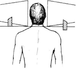
Fig. 4. Craniospinal irradiation using penumbra generators.
Spoiler technique, in which two lead wedges are used to provide satisfactory dose distribution across the field junction [8]. These lead wedges are custom de-signed (Fig. 4).
This technique is also applied for or-thogonal treatment fields. Although the thickness of the shields is specified by a time consuming dosimetry, however, it is not able to obtain a perfectly homogeneous physical dose distribution in the junctional area [6,7].
In clinical practice, the fields are usually abutted at the surface if the tumor is super-ficial at the junction point. Care is however taken that the hot spot created due to the overlap of the beams at depth is clinically acceptable, considering the magnitude of the overdosage and the volume of the hot spot. In addition, the dosage received by a sensitive structure such as the spinal cord must not exceed its tolerance dose.
For the treatment of deep-seated tumors
such as in the thorax, abdomen, and pelvis, the fields can be separated on the surface. It is assumed in this case that the cold spots created by the field separation are located superficially, where there is no tumor.
To improve this treatment and eliminate hot and cold spots, it is necessary to intro-duce a new method for treating adjacent fields.
Methods
We will consider the lengths of two adja-cent fields as AB= a,and AB’=band the position of radiation sources as S1and S2
re-spectively (Fig. 5). When one treats the pa-tient with these two fields, hot spots will be created as mentioned above. To prevent such an effect the following steps can be taken:
Rotating the treatment couch for 90° horizontally.
Fig. 5. Rotation of treatment couches 90º, Rotation of gantry for angles αandβtowards the common edge
of the treatment volume for positions S1and S2respectively while moving the treatment couch for h1and h2
towards the source for two parts and treatment field, provide an inhomogeneity of about 2%.
At the position S1, for treatment of the
first field the gantry rotates for the angle a towards the common edge of the treatment volume (i.e. A in Fig. 5).
When the treatment machine adjusts at position S2, the gantry rotates for angle b
towards the common edge (A) of the treat-ment volume.
These two fields have a party ray perpen-dicular to the surface of the treatment couch at point A.
The result of this treatment technique is as follows:
The central axis of the treatment fields is not perpendicular to the surface, which is not important in the treatment planning. However, it is convenient to correct it by isodose shift method [14].
The treatment fields increase for a length of X1 and X2 at the surface of the body,
which is very small compared with the length of the fields, and can be omitted.
To omit the X1 and X2, the treatment
couch moves for h1and h2centimeters
to-ward the source. Where:
Sinα= a/2d, Sinβ= b/2d, d= S1O=S2O’ (1)
According to Fig. 5 one can write:
h1=X1cotan2β , h2=X2cotan2β (2)
and,
X1=d’1tan2α-a , X2= d’2tan2β-b, (3)
where d’
1= S’1A and d’2= S’2A, are vertical
distances of the source S’from the body for two fields.
Substituting eq.(3) in eq.(2) with some calculations one can obtain:
h1=(a/2) tanα and h 2=(b/2) tanβ,
where
d’1= d2– a2/4 and d’2= d2– b2/4
For example if a=b=25cmand, d= 80cmone
can obtain:
α=β= 9° and, h1=h2= 2cm
but, if a=25cm,b=15cmand d=100cm,
then:
α=7°, β= 4.3°, h1=1.6cm and h2= 0.6cm
Therefore, when SSD increases, α, β, h1
and h2decrease.
Results
In clinical practice, a completely homo-geneous physical dose distribution in the junctional area of two adjacent fields is vir-tually impossible to obtain. Even if a rea-sonably homogeneous physical dose distri-bution is obtained, because of time-dose re-lationship, the biological effective dose may be heterogeneous [20]. The matching between the mantle and the para-aortic fields in the treatment of Hodgkin’s disease is of particular concern because of the need to avoid an overlap of a portion of the spinal cord. If this overlap occurs, the dose that is received can cause irreversible neu-rological damage [21].
The most commonly used method for matching adjacent fields in Hodgkin’s dis-ease is the geometric matching technique [22]. The distance between the fields at the patient’s surface is calculated so that the adjacent field edges join at the chosen depth, usually at the midline. However, the field lengths and the depths to the central axis plane are commonly different between the mantle and the para-aortic field leading
to inhomogeneity due to different beam di-vergences. Additionally, the formula for gap calculation assumes the patient’s sur-face is flat, not taking into account the ef-fect of the sloping body surface.
Lutz and Larsen [23] described a tech-nique to match the mantle and para-aortic fields with the patient treated alternatively in supine and prone position. Film dosime-try in a solid plastic phantom with same setup showed about 15-20% higher dose distribution at the level of the spinal cord. This was attributed to beam divergence dif-ferences between the larger mantle and shorter para-aortic fields.
Keys and Grigsby [24] proposed a modi-fication of the existing formula for calcu-lating the gap for the fields on a sloping surface. The effect of sloping surface can cause about 1 centimeter overlapping at the spinal cord because of erroneously posi-tioning the para-aortic field at a distance calculated by a standard formula from the edge of the mantle light field on the skin surface. Film dosimetry using the skin gap calculated using the standard formula showed maximum dose in the junctional area to be 145% and spinal cord dose 125%. Isodose curves using the modified formula to calculate the gap demonstrated much more uniformity at the junction, with the region near the spinal cord receiving 115% of the central axis dose.
An isocenter shift method was intro-duced by Tae et al [15] and was more accu-rate and easier than the others were. Al-though after a film dosimetry they demon-strated no hot spots, but a cold spot will be created as low as 50 %.
A dynamic supraclavicular field-match-ing technique for head and neck cancer pa-tients treated with IMRT was introduced by Duan et al [25].
The results of their activity show an
av-erage inhomogeneity range of 6%. They compared their method with the conven-tional single-isocenter and half-beam tech-nique and they mentioned an inhomogene-ity for the later technique as high as 22.8%. This new technique has been applied for the treatment of spinal cord with two adja-cent fields. Dosimetry showed a maximum dose in the juctional area as much as 102%. The same results could be obtained by us-ing the isodose curves for the adjacent fields.
Conclusion
A comparison between the new tech-nique and all the previous methods, men-tioned above, provides superior dose ho-mogeneity not only in the abutment region but in the upper and lower regions as well.
In some cases, the measurements have shown that the dose inhomogeneity is as large as 45% [25]. Compared with the dy-namic intensity-modulated radiotherapy (IMRT), this technique also provides supe-rior dose homogeneity [25] such that inho-mogeneity becomes about 2%.
From a practical point of view clinical radiation therapy applying this technique for treatment planning is very simple and there is no delay time in treatment of pa-tients.
The physicist can calculate α,β, h1and h2
from the mentioned relations and apply the steps 1, 2 and 3 for treatment of patients (Fig.5).
References
1. Lance JS, Morgan JE. Dose distribution be-tween adjoining therapy fields. Radiology 1962; 79: 24-27.
2. Glenn DW, Faw FL, Kagan RA. Field separa-tion in multiple portal radiasepara-tion therapy. AJR 1968; 102: 199-201.
3 .Faw F, Glenn DW. Further investigations of physical aspects of multiple field radiation therapy. AJR 1970; 108: 184-187.
4. Page V, Gardner A, Karzmark CJ. Physical and dosimetric aspects of the radiotherapy of malignant lymphomas: The inverted-Y technique. Radiology 1970; 96: 619-622.
5. Agarwal SK, Marks RD , Constable WC. Adja-cent field separation for homogeneous dosage at a given depth for the 8 MV (Mevatron 8) linear accel-erator. AJR 1972; 114; 623-629.
6. Armstrong DI, Tait JJ. The matching of adja-cent fields in radiotherapy. Radiology 1973; 108: 419-420.
7. Hale J, Davis LW, Bloch P. Portal separation for pairs of parallel-opposed portals at 2 MV am\nd 6 MV. AJR 1972; 114: 172-174.
8 .Griffin TW, Schumacher D, Berry HC :A tech-nique for cranial-spinal irradiation. Br J Radial 1976; 49: 887-888.
9. Williamson TW. A technique for matching or-thogonal megavoltage fields. Int J Radiat Oncol Bi-ol Phys 1979; 5: 111-117.
10. Bukovits A, Deutsch M, Slayton R. Orthogo-nal fields: variations in dose vs. gap size for treat-ment of the central nervous system. Radiology 1978; 126: 795-796.
11. Gillin MT, Kline RW. Field separation be-tween lateral and anterior fields on a 6MV linear ac-celerator. Int J Radiat Oncol Biol Phys 1980; 6: 233-234.
12. Werner BL, Khan FM, Sharma SC. Border separation for adjacent orthogonal fields. Med Dos 1991; 16: 79-80.
13. Hopfan S, Simpson L. Clinical complica-tions arising from overlapping of adjacent radiation fields-Physical and technical considerations. Int J Radiat Oncol Biol Phys 1977; 2: 801-802.
14. Khan FM. Separation of adjacent fields. The physics of radiation therapy. 3rd ed. Baltimore: Williams &Wilkins; 2003. pp. 287-299.
15. Park TL, Meek AG, Reinstein LE, Pai S. A new Isocenter shift method for ideal geometric matching of two adjacent fields. Med Dos 1995; 20: 195-200.
16. Moss WT, Brand WN, Battifora H. Radia-tion Oncology, 4th ed. St Louis: Mosby; 1973. pp. 576-577.
17. Price RA, Ayyangar KM. A method of gap
and field size determination for abutting a treatment field to a previously treated area. Med Dos 1996;
21: 83-86 .
18. Pickett B, C. Shostak C, Karzmark CJ, Den Haak KV. An approach to abutting adjacent fields. Med Dos 1989; 14: 203-207.
19. Dobrowsky W. Treatment of choroid metas-tases. Br J Radiol 1998; 61: 140-142.
20. Tacher M. Time-dose effects in the matching of adjacent radiotherapy fields. Radiology 1978; 126: 253-254.
21. Hellman S, Jaffe ES, DeVita VT. Hodgkin’s disease. In: DeVita, VT.; Hellman S, Rosenberg SA, editors. Cancer: principle and practice of oncology. Philadelphia: J B Lippincott Company; 1989. pp. 1711-1723.
22. Glasgow GP, Samiere VA, Purdy JA. Exter-nal beam dosimetry and treatment planning. In: Perez CA, Brady L W, editors. Principles and Prac-tice of Radiation Oncology. Philadelphia: Lippin-cott Company; 1987. pp.176-177.
23. Lutz WR, Larsen RD. Technique to match mantle and para-aortic fields. Int J Radiat Oncol Bi-ol Phys 1983; 9: 1753-1756.
24. Keys R, Grigsby PW. Gapping fields on slop-ing surfaces. Int J Radiat Oncol Biol Phys 1990: 18: 1183-1190.
25. Duan J, Shen S, Spencer SA, Ahmed RS, Popple RA, Ye SJ, Brezovich IA. A dynamic supra-clavicular field-matching technique for head and neck cancer patients treated with IMRT. In J Radiat Oncol Biol Phys 2004; 60: 959-972.