Volume 56, 2018, Pages 23–34
Proceedings of the 5th International OMNeT++ Community Summit
Community-based Mobility Model and Probabilistic
ORBIT Mobility Model Implementations in OMNeT++
Vishnupriya Kuppusamy, Leonardo Sarmiento, Asanga Udugama, and
Anna F¨
orster
Sustainable Communication Networks, University of Bremen, Bremen, Germany {vp,adu,annafoerster}@comnets.uni-bremen.de,[email protected]
Abstract
Simulations of Opportunistic Networking (OppNet) protocols require the use of suitable synthetic mobility models or real world traces. Many synthetic mobility models have been proposed based on the study of human mobility individually and in groups. Opportunistic Protocol Simulator (OPS) is a budding simulator which is based on OMNeT++ to simulate OppNets. However, compared to other OppNet simulators in the literature, only very few synthetic mobility models exist in OMNeT++ currently, restricting the simulation of OppNets to using the existing mobility models or traces. In this paper, we develop two more synthetic mobility models in OMNeT++ namely community-based mobility model and probabilistic ORBIT based mobility, which can enhance the simulating environment available for OppNets in OMNeT++.
1
Introduction
Opportunistic Networks (OppNets) enable the nodes to communicate without the need for an infrastructure [1]. The nodes communicate directly with each other whenever they are in the connection range of each other. These networks were initially proposed to be used only in challenging environments like disaster scenarios and areas with lack of infrastructure development. However, they have the potential to cater to a variety of highly scalable wireless networks such as Internet of Things (IoT).
Performance evaluations of OppNets consist of two main components; the working of for-warding protocols themselves and the evaluation of these protocols for a highly scalable and dynamic network like OppNets. The dynamic nature of OppNets is highly influenced by the mobility of the nodes. Owing to the scalability and mobility of OppNets, evaluating their performance analysis in a large-scale real-world environment is still a challenge. Real testbeds often mirror the real world closely, however does not offer flexibility in terms of scalability and repeatability. Therefore, simulators are widely preferred for the performance analysis of these networks.
and are scenario-specific. Though there are tools such as BonnMotion [3] to extract and modify these traces to a certain extent, they don’t offer a wide variety of scenarios. Further, there is a lack of flexibility in customization and extension of these traces. On the other hand, synthetic mobility models are flexible and adaptable for setting up configurations based on the need.
Synthetic mobility models are developed based on human mobility studies and human move-ment in the real world. Some models have been built from traces, while few others are analyti-cally modeled adhering to the observations of human behavior [4]. Thus, the variety of proposed synthetic mobility models ranges from random walks to map-based sophisticated models with pedestrian and vehicle movement. However, the implementation of mobility models in simula-tors for OppNets have been a few and requires significant attention as mobility is one of the major factors driving OppNet performance [5].
Of the widely used OppNet simulators, the ONE [6] has few implementations of highly used mobility models such as Random waypoint, Home Community Mobility Model (HCMM) and Working-Day Movement model (WDM) [7]. Adyton [8] supports only real-world traces which further need to be adapted as per the format required by Adyton. Opportunistic pro-tocol Simulator (OPS) [9], currently the only simulator for OppNets based on OMNeT++ has linear movement, Random Walks (RW), Random Waypoint (RWP), Small Worlds In Motion (SWIM) [10] and provision to use traces [11]. However, RW and RWP are not realistic for mod-eling human mobility [12], as humans don’t move in random directions with random speeds. The limited range of mobility models in OPS have restricted majority of the OppNet simulations to use traces or SWIM [13]. Further, the social groups based mobility and individual users’ schedule based mobility are highly relevant in simulating OppNet forwarding protocols. As OM-NeT++ has the essential modules to implement new synthetic mobility models [14], [15], this paper brings forth the implementation of Community-based Mobility Model (CMM) [16] and probabilistic ORBIT [17], which would expand the horizon for upcoming OppNet simulations using OPS and OMNeT++.
The rest of the paper is organized as follows: Section2and Section3briefly gives an overview of CMM and ORBIT and their main functionalities. Section4 presents the implementation of CMM and ORBIT in OMNeT++. Section5 discusses the simulation results and validation of the implementations of those mobility models. Section6concludes the paper and addresses the future work.
2
Community based Mobility Model
The main idea of CMM is that the users with strong social network ties in real world tend to move in same geographical space [16] and hence, these social relationships can be used to model human mobility patterns. CMM models social relationships by using social network information to group users into communities. The social network information from the model is taken as input which is an interaction matrix’I’, and the entries of this matrix are weights’w’ of edges between two nodesi andj. These weights are interaction indicators representing the strength of social interactions between the respective nodes. From the interaction matrix, a connectivity matrix is created by selecting those edge weights that cross a certain threshold (>0.25). This value is used by authors in [16], based on their studies of the social network trace considered as input for the interaction matrix in their simulation.
divided into equal size of non-overlapping grids and each community is assigned to an exclusive grid. The nodes belonging to the same community often move in same geographical space and the next target location of the nodes is based on the social attractivity of grids.
Social attractivity of a grid at any time is calculated by the sum of the interaction indicators of relationships between the nodeiand all other nodes in that respective grid normalized by the total number of nodes in that square. The social attractivity of all the grids in the simulation area for a node i is calculated and then the node i moves to the grid with highest social attractivity. The next location of each node is selected in this manner which can be in the same grid or in a different grid depending on the social attractivity. The exact position in the selected grid is chosen randomly. There is a reconfiguration interval after which the communities are reset which captures the variations in human movement based on the time of the day.
3
Orbit Mobility Model
ORBIT mobility for MANETs is based on the sociological movement pattern of users [18]. Most of the users’ movements are in a terrain consisting of certain locations or around these locations. ORBIT mobility model is not concerned about the exact coordinates or positions of the users at any instant of time. Instead, it focuses on identifying the approximate region where the user could be located at any given time. ORBIT assumes that users’ spend most of their time only in few of the regions or locations in the simulation space and they do not visit every location in the simulation space. These particular locations are usually visited by users in some probabilistic manner which is determined by their individual schedules and hence, are a part of their mobility profiles. During weekdays and weekends, users usually might follow different movement patterns depending on their activities and individual schedules. This model is called ORBIT because it is based on the fact that users’ typically move around these few locations in a sequence, however not necessarily the same sequence everyday.
ORBIT divides the simulation area into locations of different or equal sizes called hubs. A hub can be a classroom, a shopping mall, home, different rooms in a home, an entire street and so on. The concept of a hub can vary based on simulation scenario, however a simulation area is divided into hubs to capture the movement profile of the nodes. The total number of hubs in the simulation area is given byTotal Hubs. AHub list is associated with every user and the users orbit in these hubs in a partially deterministic sequence. The exact position of the users inside the hubs are not modeled by ORBIT, as its main goal is macro-level mobility. Every user or a node spends a certain amount of time in each hub given byHub stay time. The hub list assigned to each node along with its hub stay times is named an Orbit. An orbit can be reset by anOrbit Timeout, after which the hub lists and hub stay times associated with nodes can be redefined.
Four different orbits are discussed in [18] such as random orbit, uniform orbit, restricted orbit and overlaid orbit. Additionally, probabilistic orbit [17] is discussed in the improvement of SOLAR. In this model, nodes move to different hubs with a probabilistic association. This can reflect in the selection of the next position and the hub stay time. Further, it allows the flexibility for the nodes to visit some hubs frequently and to stay in some hubs for a longer time.
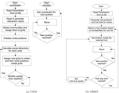
(a) CMM (b) ORBIT
Figure 1: Implementation flow chart of CMM and ORBIT
model in a generalized manner. For instance, all the nodes change their orbit movement after orbit timeout and this timeout is the same value for all the nodes in the simulation, which is not exactly the case in reality. The speed of a node within the same hub and between different hubs are given byIntra-hub speedandInter-hub speed respectively, because nodes usually follow different modes of transport depending on the distance between their current and next target positions. However, this choice totally depends on the way hubs are partitioned.
4
Implementation in OMNeT++
The CMM and ORBIT mobility model implemented in OMNeT++ uses the INET Mobility framework. The flow charts for both mobility model implementations are shown in Figure 1
and the implementations are available in Github1. With reference to the implementation, users,
hosts and nodes are used interchangeably and refer to the same meaning. A position refers to the exact coordinates of a node and a location refers to an area where many nodes can be present. The implementations have two phases namely initialization phase and mobility phase.
4.1
Community-based Mobility Model Implementation
A separate folder named social is added in mobility of inet for CMM as CMM uses social network interactions and the interaction matrices are given as input files or generated randomly and placed in this folder.
CMM has two modules namely a CMM coordinator and CMM member. The CMM coordi-nator does the necessary preprocessing and calculating the grid locations for all nodes for every mobility update. The next target position of a node is influenced by the current locations of its social network contacts and hence, a node needs to know much more than its own current location to calculate the social attractivity of a grid. This operation is simplified by using a centralized module that keeps track of the locations of all the nodes in the simulation at any given time during the simulation. Thus, the CMM coordinator does all the pre-processing steps till mobility phase and particularly calculates the next target location and makes it available for the nodes. The CMM member module implements the mobility functions of a node. A CMM member asks the CMM coordinator for the next target location and uses the function
move()to reach the next location. The next target location can be in the current residing grid or in a different grid based on the social attractivity of grids as described in section2.
4.1.1 Initialization Phase
All the tasks in initialization phase is done byspeeds CMM coordinator.
Loading or creating the interaction matrix: It is a matrix depicting the probabilities of interaction between every pair of nodes. It is a n x n matrix where n is the number of nodes. It can be generated with random probabilities or the matrix can be read from a file. If the interaction matrix is to be generated randomly, then the functionsetInteractionMatrix()
performs this operation. If the interaction matrix is to be read from a file, then the function
loadInteractionMatrix()performs this operation. The option of reading the interaction matrix from a file enables the users to load predefined interaction matrices from real-world traces.
Forming communities: From the interaction matrix, the CMM coordinator makes all the values above a certain threshold (>0.6) as 1 leading to the creation of the connectivity matrix. The authors in [16] used a real-world trace which was not available to us and hence, we gen-erated a random interaction matrix. In order to avoid having a complete random community assignment, we selected a higher threshold of 0.6 as we required communities with greater inter-action compared to the interinter-action levels selected by authors in [16]. The entries of connectivity matrix gives the nodes that interact with each other more often.
Following the connectivity matrix, communities are formed by removing the node with high-est number of connections and all the nodes connected to the node with highhigh-est connectivity. The group of these severed nodes become a community. This procedure is repeated and commu-nities are formed until all the nodes are covered. If there is a lone node, it becomes a community on its own. The functioncreateCMMCommunities()makes these communities and the output is the number of communities and the community to which a node belongs.
of non-overlapping grids which are squares of length and breadth given by grid length. The functionassignCommunitiesToGrids()assigns the communities to grids randomly.
4.1.2 Mobility Phase
In the mobility phase, the next target position of each node is calculated based on the social attractivity factor. The function calculateSocialAttractivity() in CMM coordinator calculates the social attractivity of grids for each node and returns the community with highest social attractivity for each node. The output of this function tells the node which grid it should move to based on the locations of its social network connections. The node then usessetTargetPosition()
and selects a random position in the target grid, sets its speed and then uses themove()function to move linearly to the exact position in the target grid. The CMM member performs the actual mobility in the mobility phase, though the location decision is performed in the CMM coordinator.
4.2
ORBIT Implementation in OMNeT++
ORBIT mobility reads the following parameters from ini file and sets up the hub locations and hub positions in the initialization phase. The parameters are taken from [18], where this model was proposed.
4.2.1 Initialization Phase
Number of Hubs: The total number of hubs in the given simulation area is set by this parameternumberOfHubs. It was set to 10 in our simulation.
Hub stay time: The time spent by a node in a hub is given byhubStayTime. This time can vary for different nodes in different hubs. It was set as a value between 50 and 100 seconds.
Intra-hub speed: Nodes useintraSpeed to move if the next position is within the same hub. It was set as a value between 1 - 3 meters/second considering pedestrians.
Inter-hub speed: Nodes use interSpeed when moving to a different hub than the current hub location. It was set as a value between 1 - 6 meters/second considering pedestrians and bicycle users.
Hub list: Every node has ahubList which can be generated by a matrix or read from a file. A node moves between the hubs assigned to it. It does not move to any hub that is outside of its hublist.
Hub size: The area of each hub is setup inside the simulation region as given by hubSize. Hub size in our simulation was 200 m x 200 m.
4.2.2 Mobility Phase
The node decides its next location based on its hub list and the probabilities associated with the hubs in the hub list. The node generates a random number between 0 and 1 and uses it as a threshold to selects the hub with probability close to the obtained threshold. The node sets a random position inside the selected hub and moves linearly to that position using move(). The node selectsintraHubSpeed orinterHubSpeed based on the choice of the next hub. Till the expiration of hubStayTime, it moves to a random position in the same hub for every mobility update. After the hubStayTime expires, the node moves to a different hub in the consequent mobility update.
5
Simulation and Results
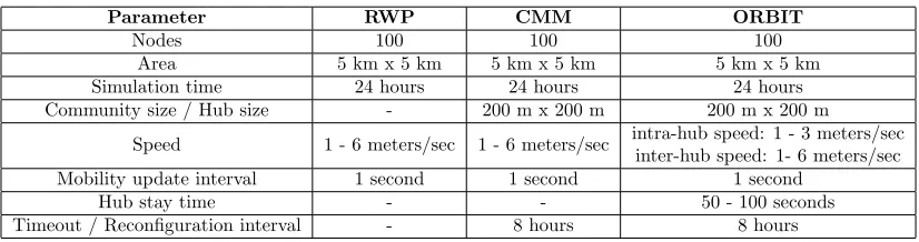
The ORBIT and CMM implementations in OMNeT++ were simulated with the setup as given in Table1. CMM and ORBIT simulations were reset after a reconfiguration interval or timeout period of 8 hours. Hence, the behaviour of the nodes were refreshed thrice in total simulation time. The objective here is to capture the different movement patterns of the nodes within a single day.
Parameter RWP CMM ORBIT
Nodes 100 100 100
Area 5 km x 5 km 5 km x 5 km 5 km x 5 km Simulation time 24 hours 24 hours 24 hours Community size / Hub size - 200 m x 200 m 200 m x 200 m
Speed 1 - 6 meters/sec 1 - 6 meters/sec intra-hub speed: 1 - 3 meters/sec inter-hub speed: 1- 6 meters/sec Mobility update interval 1 second 1 second 1 second
Hub stay time - - 50 - 100 seconds
Timeout / Reconfiguration interval - 8 hours 8 hours
Table 1: Simulation Configuration for RWP, CMM and ORBIT mobility models
Mobility model Number of events Simulation time Real-time Completion
CMM 8690795 86400 seconds 41.7975 seconds 100 %
ORBIT 8675916 86400 seconds 30.7734 seconds 100 %
RWP 8644602 86400 seconds 30.2608 seconds 100 %
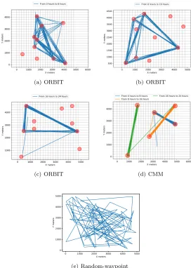
(a) ORBIT (b) ORBIT
(c) ORBIT (d) CMM
0 1000 2000 3000 4000 5000
X meters 0
1000 2000 3000 4000 5000
Y meters
(e) Random-waypoint
Figure 2: Trajectories of ORBIT, CMM and RWP mobility models
These simulations test the basic operation of CMM and ORBIT models, and the results are compared with RWP in terms of mobility trajectory of a single node as shown in Figure2. The shaded circles in Figure 2(d) shows the different communities for CMM and the shaded circles in Figure 2(c) shows the different hubs for ORBIT respectively. The trajectories in Figure 2(d) verifies that the nodes in CMM move along with their social network contacts frequently, spending more time in some of the grids and not visiting some grids at all. In ORBIT, the nodes visit certain hubs frequently and does not visit other hubs as seen in Figure2(c). On the other hand, the nodes in RWP move over the entire simulation area.
4000 5000 6000 7000 8000 9000 10000 Number of contacts between nodes (nodes) 0
5 10 15 20 25
Percentage of occurrences(%)
(a) Total number of contacts between nodes
0 500 1000 1500 2000 2500
Contact time between two nodes (s) 103
102
101
100
Percentage of occurrences(%)
(b) Contact times between nodes
0 250 500 750 1000 1250 1500 1750
Time between node's contacts (s) 104
103
102
101
100
101
Percentage of occurrences(%)
(c) Time interval between contact times
0 5 10 15 20 25 30
Group size (nodes) 0
2 4 6 8 10
Percentage of occurrences(%)
(d) Community size
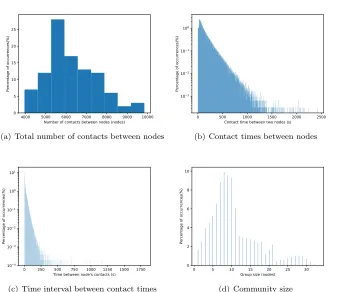
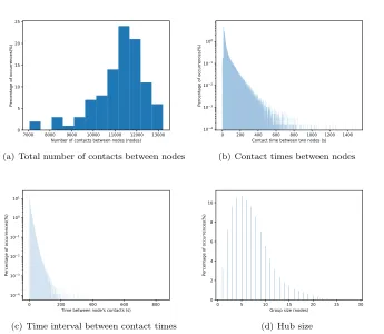
Figure 3: Community-based Mobility Model (CMM)
randomly selects a random position in the simulation area for every node during the mobility update and thus, has the fewer events of all the three mobility models under consideration in this paper.
Further, the contact times and number of contacts for CMM, ORBIT and RWP with the chosen simulation configuration is shown in Figure 3, Figure 4 and Figure 5. Figure 3(a)
shows that 25 percentage of the nodes in CMM had approximately 6000 contacts during the entire simulation time as the nodes are highly likely to move together with nodes of same community rather than meeting new contacts. The nodes in CMM has an average of 6290 contacts throughout the simulation. Figure3(b)shows that the contact times between nodes or plainly contact times in CMM is distributed between 1 and 1500 seconds. The high contact times in CMM are due to the fact that nodes with strong social ties move within same geographical space and hence, stay often in contact. Figure 3(c) shows that within 1 to 250 seconds, the nodes meet a neighbor and hence, this represents the time between contact times. Time between contact times refers to the time interval during which the nodes were not able to meet any contacts. Figure3(d) shows that the community size in CMM varies from 1 to 30 during the simulation. For 10 percentage of the simulation, the number of nodes in a community was 7.
7000 8000 9000 10000 11000 12000 13000 Number of contacts between nodes (nodes) 0
5 10 15 20 25
Percentage of occurrences(%)
(a) Total number of contacts between nodes
0 200 400 600 800 1000 1200 1400
Contact time between two nodes (s) 104
103
102
101
100
Percentage of occurrences(%)
(b) Contact times between nodes
0 200 400 600 800
Time between node's contacts (s) 104
103
102
101
100
101
Percentage of occurrences(%)
(c) Time interval between contact times
0 5 10 15 20 25 30
Group size (nodes) 0
2 4 6 8 10
Percentage of occurrences(%)
(d) Hub size
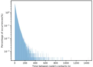
Figure 4: ORBIT Mobility
CMM as the node movements in ORBIT are not dependent on other nodes. Hence, the nodes using ORBIT is more likely to make more contacts compared to CMM. However, the contact times from Figure4(b)are in the range of 1 to 450 seconds which is lesser than CMM, as the node movements in ORBIT are not dependent on other nodes. Hence, the nodes in ORBIT are not likely to be in contact often for a longer contact duration in comparison with CMM. Figure4(c)shows the time interval between contact times is 1 to 200 seconds and Figure4(d)
shows the hub size. The hub size was approximately 6 for 10 percentage of the simulation time. Figure 5 shows the results of RWP to compare the with the results of CMM and ORBIT in Figure3 and Figure4. From Figure5, it can be seen that the number of contacts in RWP is lesser compared to CMM and ORBIT as the movement is more random and hence, does not support meeting contacts on purpose. The contact times and time between contacts are also dependent on this random movement behaviour of RWP.
6
Conclusion
3400 3500 3600 3700 3800 3900 4000 4100 Number of contacts between nodes (nodes) 0
5 10 15 20
Percentage of occurrences(%)
(a) Total number of contacts between nodes
0 500 1000 1500 2000 2500
Contact time between two nodes (s) 103
102
101
100
Percentage of occurrences(%)
(b) Contact times between nodes
0 200 400 600 800 1000 1200 1400
Time between node's contacts (s) 103
102
101
100
Percentage of occurrences(%)
(c) Time interval between contact times
Figure 5: Random-Waypoint Mobility (RWP)
between very few communities and the nodes in ORBIT move only between the hubs in their hub list. The contact durations and the number of contacts are also influenced by these behaviours, which also aligns with the proposed pattern in [16] and [17]. The current implementations are evaluated only using the simulation parameters and thus, there is a potential to evaluate these implementations using traces in the future work.
References
[1] Vin´ıcius FS Mota, Felipe D Cunha, Daniel F Macedo, Jos´e MS Nogueira, and Antonio AF Loureiro. Protocols, mobility models and tools in opportunistic networks: A survey. Computer Communi-cations, 48:5–19, 2014.
[2] Tristan Henderson and David Kotz. {CRAWDAD}wireless network data citation bibliography. 2015.
[3] Nils Aschenbruck, Raphael Ernst, Elmar Gerhards-Padilla, and Matthias Schwamborn. Bonnmo-tion: a mobility scenario generation and analysis tool. InProceedings of the 3rd international ICST conference on simulation tools and techniques, page 51. ICST (Institute for Computer Sciences, Social-Informatics and Telecommunications Engineering), 2010.
[5] Suvadip Batabyal and Parama Bhaumik. Mobility models, traces and impact of mobility on oppor-tunistic routing algorithms: A survey. IEEE Communications Surveys & Tutorials, 17(3):1679– 1707, 2015.
[6] Ari Ker¨anen, J¨org Ott, and Teemu K¨arkk¨ainen. The one simulator for dtn protocol evaluation. In
Proceedings of the 2nd international conference on simulation tools and techniques, page 55. ICST (Institute for Computer Sciences, Social-Informatics and Telecommunications Engineering), 2009. [7] Frans Ekman, Ari Ker¨anen, Jouni Karvo, and J¨org Ott. Working day movement model. In
Proceedings of the 1st ACM SIGMOBILE workshop on Mobility models, pages 33–40. ACM, 2008. [8] N Papanikos, DG Akestoridis, and E Papapetrou. Adyton: A network simulator for opportunistic
networks, 2015.
[9] Asanga Udugama, Anna F¨orster, Jens Dede, Vishnupriya Kuppusamy, and Anas Bin Muslim. Opportunistic networking protocol simulator for omnet++. arXiv preprint arXiv:1709.02210, 2017.
[10] Asanga Udugama, Behruz Khalilov, Anas Bin Muslim, and Anna F¨orster. Implementation of the swim mobility model in omnet++. arXiv preprint arXiv:1609.05199, 2016.
[11] Liu Sang, Vishnupriya Kuppusamy, Anna F¨orster, Asanga Udugama, and Ju Liu. Validating contact times extracted from mobility traces. InInternational Conference on Ad-Hoc Networks and Wireless, pages 239–252. Springer, 2017.
[12] Jens Dede, Anna F¨orster, Enrique Hern´andez-Orallo, Jorge Herrera-Tapia, Koojana Kuladinithi, Vishnupriya Kuppusamy, Pietro Manzoni, Anas bin Muslim, Asanga Udugama, and Zeynep Vatan-das. Simulating opportunistic networks: Survey and future directions. IEEE Communications Surveys & Tutorials, 20(2):1547–1573, 2018.
[13] Vishnupriya Kuppusamy. Performance analysis of epidemic routing in destination-less oppnets. In2018 IEEE 19th International Symposium on” A World of Wireless, Mobile and Multimedia Networks”(WoWMoM), pages 01–03. IEEE, 2018.
[14] Behruz Khalilov, Anna F¨orster, and Asanga Udugama. Radio irregularity model in omnet++.
arXiv preprint arXiv:1709.07035, 2017.
[15] Anna F¨orster, Anas Bin Muslim, and Asanga Udugama. Reactive user behavior and mobility models. arXiv preprint arXiv:1709.06395, 2017.
[16] Mirco Musolesi and Cecilia Mascolo. A community based mobility model for ad hoc network research. InProceedings of the 2nd international workshop on Multi-hop ad hoc networks: from theory to reality, pages 31–38. ACM, 2006.
[17] Joy Ghosh, Hung Q Ngo, and Chunming Qiao. Mobility profile based routing within intermittently connected mobile ad hoc networks (icman). InProceedings of the 2006 international conference on Wireless communications and mobile computing, pages 551–556. ACM, 2006.