University of New Orleans University of New Orleans
ScholarWorks@UNO
ScholarWorks@UNO
University of New Orleans Theses and
Dissertations Dissertations and Theses
Fall 12-20-2013
Semantic Services for Enterprise Data Exchange
Semantic Services for Enterprise Data Exchange
James A. Sauvinet
University of New Orleans, [email protected]
Follow this and additional works at: https://scholarworks.uno.edu/td
Part of the Artificial Intelligence and Robotics Commons, and the Databases and Information Systems Commons
Recommended Citation Recommended Citation
Sauvinet, James A., "Semantic Services for Enterprise Data Exchange" (2013). University of New Orleans Theses and Dissertations. 1783.
https://scholarworks.uno.edu/td/1783
This Thesis-Restricted is protected by copyright and/or related rights. It has been brought to you by
ScholarWorks@UNO with permission from the rights-holder(s). You are free to use this Thesis-Restricted in any way that is permitted by the copyright and related rights legislation that applies to your use. For other uses you need to obtain permission from the rights-holder(s) directly, unless additional rights are indicated by a Creative Commons license in the record and/or on the work itself.
Semantic Services for Enterprise Data Exchange
A Thesis
Submitted to the Graduate Faculty of the
University of New Orleans
In partial fulfillment of the
Requirements for the degree of
Master of Science
In
Computer Science
by
James Sauvinet
B.S. University of New Orleans, 2010
ii
Acknowledgement
I would like to thank Dr. Tu for his guidance, encouragement and his seemingly endless supply of patience as I’ve navigated my graduate career. I also wish to thank Dr.
DePano for once helping a naïve incoming freshman through many challenges. I also wish to thank Dr. Abdelguerfi for challenging me see a side of Computer Science I had never considered before.
iii
Table of Contents
List of Figures ... iv
List of Tables ... v
Abstract ... vi
Chapter 1 ...1
Chapter 2: Background ...2
Resource Description Framework and RDF-Schema ...2
Web Ontology Language ...3
SPARQL Protocol and RDF Query Language ...4
Chapter 3: An Example ...5
Chapter 4: System Design ...8
Requirement Specification ...8
Information about Data ...9
The Data Exchange Intermediary ... 10
Joining the DEI ... 11
Search Request Processing ... 12
Chapter 5: Prototype Implementation ... 14
Introduction ... 14
The Ontology Manager and Data Exchange Intermediary ... 15
The Test for Expressive Completeness ... 18
The Data Exchange Intermediary Middleware ... 23
A Use Case Scenerio ... 23
Define Search Universe ... 24
Define Data Parameters ... 25
Perform DEI-Directed Search ... 26
Chapter 6: Sample Architectures ... 28
Sample DEI Architectures ... 28
References ... 30
Appendix A, Glossary ... 32
Appendix B, Future DEI Use Case ... 33
Appendix C, Sample Entity Relation Diagrams ... 34
Example FBI Database Schema ... 34
Example USCIS Database Schema ... 35
Example DHHS Database Schema ... 36
iv
List of Figures
Data dependencies for systems queried in the example scenario ...5
Logical view of DEI actors ...13
DEI Search Request XML Schema ...15
Class selection for DEI Directed Search ...22
Class property and search parameter selection for DEI Directed Search ...24
DEI Directed Search results ...25
Sample DEI architecture within a single geographically dispersed organization ...26
v
List of Tables
vi
Abstract
Data exchange between different information systems is a complex issue. Each system, designed for a specific purpose, is defined using a vocabulary of the specific business. While Web services allow interoperations and data communications between multiple systems, the clients of the services must understand the vocabulary of the targeting data resources to select services or to construct queries. In this thesis we explore an ontology-based approach to facilitate clients’ queries in the vocabulary of the clients’ own domain, and to automate the query processing. A governmental inter-department data query process has been used to illustrate the capability of the semantic approach.
1
Chapter 1
Following the horrible attacks of September 11, 2001, information sharing among governmental agencies, or the lack thereof, was blamed as a contributing factor in the government’s inability to stop the heinous attacks from occurring. As an attempt to rectify this deficiency, information sharing for the purposes of antiterrorism has been an agenda pushed by the administration. The Homeland Security Act of 2002 and the Intelligence Reform and Terrorism Prevention Act of 2004 are two examples of
legislation that require agencies of the Federal Government to share data amongst each other [2].
Regulations such as the Homeland Security Act of 2002 provide the catalyst for
information exchange between agencies; however, they do not address the underlying
challenges associated with implementing the exchange of information. For example, two different agencies may refer to the same concept by different names leading to vastly different data architectures. Interpretations of the same concepts may vary greatly depending on the analysts viewing the data. This leads to the question of how to facilitate effective communication among the vast number of entities, each with their own technical vocabularies, in order to share information from each domain. A shared vocabulary is required.
The challenge is further compounded when one considers the diversity in the technical solutions used to implement existing business requirements. These requirements cover a broad spectrum of domains from energy production to education, food production to space travel, national parks to live military combat simulations.
2
Chapter 2: Background
The goal of this thesis is to provide a framework for data exchange across sources spanning different business domains. Each of these sources contain data which are defined in a variety of different business vocabularies making effective communication difficult. While solutions do exist that facilitate communication between systems (i.e. web services, database links, etc.) they do not adequately address, for example, a client’s unfamiliarity with the server’s database schema, nor do they address the client’s inability to understand the server’s business vocabulary.
Our solution addresses these critical failings by providing a common vocabulary between all data providing entities. This common vocabulary is composed of OWL ontology classes that describe data concepts that are then mapped to each provider’s individual business vocabulary. Users construct search queries over one or more of these ontology classes to provide a disambiguated view of the data sought.
To implement this solution, this thesis makes extensive use of the following technologies:
Resource Description Framework and RDF-Schema
Resource Description Framework (RDF) is a language used to provide basic
information about concepts contained within a document. It provides a structure that is divided into statements consisting of subject, predicate, and object [6]. In an RDF document, resources are uniquely identified by a Uniform Resource Identifier (URI) which allows for their disambiguation from other resources. In a statement, a subject and predicate are URI-identified resources while the object can be another resource or a literal. It is noteworthy to mention while the URIs that identify these resources very closely resemble Uniform Resource Locators (URL), there is absolutely no requirement for a URL to be resolvable to any web resource.
3
http://.../A http://.../marriedTo http://.../B
and
http://.../B http://.../marriedTo http://.../A
In this example, we have explicitly defined that A is married to B, AND B is married to A. Without both of these triples, this marital relationship is not fully defined.
Web Ontology Language
Web Ontology Language, or OWL, provides a deeper level of semantic richness on top of RDF and RDFS. While RDFS can (and is) used to express simple relationships among classes of data, OWL gives us the ability to express much more complex details concerning those relationships.
Our solution organizes types of data into OWL classes that are then separated into ontologies based on their intrinsic domain (i.e. an ontology describing the concept of “Person” might be defined within the “Living Thing” ontology.) Each of these OWL classes is a collection of data and object properties that provide us with the ability to store details about each independent instance of the class.
A data property allows us to express basic information about a given class, and
therefore has a domain of the class to which it belongs, and a range of the type of data it will express. For example, if the class “Person” has a data property called
“first_name,” the domain of the property would be “Person” and the range might be “String.” An example of such a definition is provided below:
<owl:DatatypeProperty rdf:about="http://www.dei.com/person#firstName"> <rdfs:domain rdf:resource="http://www.dei.com/person#Person"/> <rdfs:range rdf:resource="&xsd;string"/>
</owl:DatatypeProperty>
An object property allows us to express a relationship between one class and another. For example, if our class “Person” has an object property called “home_address,” we could model this relationship with an object property whose domain is “Person” and whose range is “HomeAddress” where both “Person” and “HomeAddress” are distinct classes. This is an example of an object property definition:
<owl:ObjectProperty rdf:about="http://www.dei.com/person#home_address"> <rdfs:domain rdf:resource="http://www.dei.com/person#Person"/>
<rdfs:range rdf:resource="http://www.dei.com/location#HomeAddress"/> </owl:ObjectProperty>
OWL also provides us with the tools for modeling more complex relationships between resources. For example, let us revisit our RDF & RDFS example of a marital
relationship. In this example, we defined two tuples to express that A is married to B, and B is married to A. In OWL, we could reduce this to a single symmetric property using the http://.../marriedTo predicate. Using this property, A
4
Our solution make use of the OWL-API library [8] to traverse and manipulate the ontologies composing the semantic vocabulary used to exchange information between data providers.
SPARQL Protocol and RDF Query Language
SPARQL Protocol and RDF Query Language (SPARQL) is a query language for traversing RDF documents to locate resources. For example, if we had an ontology definition file that defines a class “Person” and several of its subclasses, we might use the following query to retrieve all of the subclasses of “Person”:
PREFIX rdf: http://www.w3.org/1999/02/22-rdf-syntax-ns# PREFIX owl: http://www.w3.org/2002/07/owl#
PREFIX xsd: http://www.w3.org/2001/XMLSchema# PREFIX rdfs: http://www.w3.org/2000/01/rdf-schema# SELECT ?subclass
WHERE {
?subclass rdf:type owl:Class .
?subclass rdfs:subClassOf <http://.../#Person> }
SPARQL allows for the use of prefixing which allows us to specify namespace prefixes to shorten our queries. In our above example, rdf:type, rdfs:subClassOf, and
owl:Class are prefixes, while <http://.../#Person> is non-prefixed. If we removed the PREFIX directives, we would need to include the full URI of each predicate (Example: owl:Class would become http://www.w3.org/2002/07/owl#Class)
5
Chapter 3: An Example
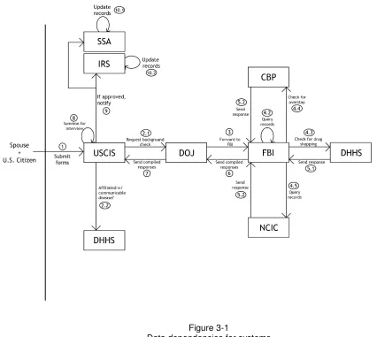
In this chapter, we frame our discussion around an example scenario. In this example, several governmental departments, The Department of Justice (DOJ), the Department of Homeland Security (DHS), and the Department of Health and Human Services (DHHS) have a requirement to share information with agencies within their respective departments. We will begin by outlining a factitious process by which the foreign-born spouse of a United States citizen obtains I-551 status, also known as Permanent Residency. It is noteworthy to mention that while this process is outlined sequentially, step execution can occur in parallel.
Our factitious process begins with the citizen and spouse completing several forms which are then submitted to the United States Citizenship and Immigration Services (USCIS), an agency within the Department of Homeland Security. From the standpoint of the citizen and his spouse, the remainder of the process appears to be completely
handled by USCIS; however, several interagency procedures must be completed prior
to issuing a permanent residency card.
After the citizen and his spouse’s forms are entered into the USCIS computer system, processing begins to determine whether or not immigration benefits should be awarded to the spouse. The first step in this process is for a USCIS officer to obtain from the Federal Bureau of Investigations (FBI), an agency within the DOJ, a complete history of the immigrant’s criminal record. This request is formalized and forwarded by the USCIS officer to the DOJ for fulfilment by the FBI.
After receiving a request for a person’s criminal history, the DOJ leadership initiates a “background check” with the Federal Bureau of Investigations (FBI). In addition to consulting their own records, the FBI will query the National Crime Information Center (NCIC), an information system maintained by the DOJ, to provide a complete look into the applicant’s criminal past.
6
Also as an additional portion of the FBI’s criminal history check, the spouse’s previous immigration history is checked. This mission is carried out by the Customs and Border Protection (CBP) who tracks movement into as well as out of the country. If the spouse has ever overstayed beyond the terms of her admission into the United States, CBP would have this information and would, at this step, provide it to the FBI as part of the spouse’s criminal history. This check would require information exchange between the FBI and the CBP.
After all of the results are compiled by the FBI, they are sent back to the USCIS. Once the USCIS receives the complete criminal record for the individual, the officer
completing the case is required to make a determination whether or not the intending immigrant poses a significant health risk to the United States. Affliction with specific communicable diseases may disqualify her from obtaining permanent residency. Prior to filing the application paperwork for the permanent residence process, the applicant is required to appear before a “Civil Surgeon” in her state of residence for a medical exam which includes laboratory work. At the completion of the exam, the civil surgeon enters the results of the exam into a Department of Health and Human Services (DHHS) database. The USCIS officer handling the case queries the DHHS system for the corresponding information.
After the USCIS receives both a complete criminal history of the prospective immigrant and her medical records, the US citizen and his spouse are summoned for a mandatory interview with a USCIS officer. After the interview is concluded, the officer makes a determination as to whether or not the spouse should receive permanent residency within the US.
If the applicant is granted permanent residence, her new legal status is forwarded to several other government entities. First, the Internal Revenue Service (IRS) is notified to ensure the new resident files an accurate tax return. Next the Social Security
Administration (SSA) is notified. This SSA update allows the new immigrant to qualify for an unrestricted social security card which must be obtained prior to accepting employment.
7 Figure 3-1
Data dependencies for systems queried in the example scenario.
8
Chapter 4: System Design
Requirement Specification
In our example scenario, all data exchanges are conducted electronically, and figure 3-1 shows a connection scheme that links all pertinent data sources. There are a number of methods to facilitate data exchange. For example, creating a database link between the source and target database systems is a solution found in many legacy systems.
A database link allows a user (with appropriate permissions) on one side to query data stored physically on the other side. While this does permit data to be exchanged between two end systems, a precondition is that the querying party (user and/or software application) understands the schema of the target database.
The database link solution has at least three serious drawbacks. First, it requires the exchange of database login credentials between two separate business entities which presents serious security concerns. Second, the user side is completely dependent upon the relational schema of the target database. A modification to the target database’s schema may “break” user queries. Finally, such a solution requires large amounts of planning, maintenance, and auditing which makes it costly.
For example, let us assume that at some point in the future a new organization is created within the Department of Homeland Security that tracks a certain metric that becomes required in the permanent residency application process. In this case, a new link between USCIS and the new agency would need to be built. After the link is built, application code will need to be created (on both sides) to request and display the required information. This process will repeat for every new “data link” added, not just for the newly created system, but also include any existing system that utilizes the new system’s data.
9
For example, if the United States Army wants to assist veterans with career placement, it should be aware of the Department of Labor’s (DOL) job data and career placement services. On the other hand, if the DOL wants to provide automated job-seeker services for veterans, its information systems must understand the skills each veteran has acquired during their military service. These skills are usually described by military skill codes such as NCD, NC, or NR [12] [13].
We propose a solution to help the users query data using their own business language, and search across multiple sources, each in their own (potentially different) business language. The following guidelines summarize its interoperability:
1. A potential solution shall not require a change to the existing data architecture or code base of any existing system.
2. A potential solution shall provide a method for a user to locate data in the custody of another entity without a priori knowledge of the database schema.
3. A potential solution shall allow exchange of data regardless of the specific database technology being used to store the data.
4. A potential solution shall not require data owners to relinquish ownership of their data to a central, “authoritative” source.
Guideline one can be seen expressed in the SOA-implementing technology of Enterprise Service Bus (ESB). An ESB is a technology that allows for message passing between information systems participating in a SOA environment. It facilitates the interoperation [5] of systems via its ability to, at a low level, translate protocols between each other [10].
Guideline two addresses items scoped within the goal of UDDI: the ability to locate and utilize some service [11]. In our case, a user should utilize some functionality to locate specific data without having to know the specifics of how the data is stored.
Guideline three addresses the realities involved in exchanging data between database implementations and requires interoperability with all such systems. This requirement again lends itself to the goals implemented by the ESB.
Guideline four provides the assertion that our solution does not consolidate data into an authoritative source, and must leverage the existing data sources to fulfil data search requests (interoperability over integration [5]).
Information about Data
Conceptually, our solution is metadata-centric. In addition to the details about the data, we also need to understand how each domain of data relates to eachother on a
10
According to the W3C, OWL “is designed for use by applications that need to process the content of information instead of just presenting information to humans.” [1] It leverages the flexibility of eXtensible Markup Language (XML) to allow us to describe data classes and their individual properties (i.e. a Human has the property of being male or female.) In addition to describing data, it also provides a platform for defining formal axioms such as asserting an object belongs to a specific domain (i.e. Eric is a Human), or defining the domain and range of a specific property. With these axioms defined within an OWL ontology, information systems are able to become aware of the concerned domains of discourse.
The Data Exchange Intermediary
Our approach proposes the creation of an intermediate system which we refer to as the Data Exchange Intermediary, or DEI. This is a metadata portal that provides the user with the functionality to perform a search. The DEI presents the user with the domains of discourse that are composed of a vocabulary defined in OWL. This allows the user to specify a search based on his or her domain knowledge about entities and the
relationship between them within one or multiple domains. The DEI then serializes the request into a transportable format and forwards the request onward for fulfillment.
Defining metadata formally using an ontology has serious advantages over performing simple key-word searches. Instead of defining a search in terms of a word or phrase, the DEI allows the users to select classes (concepts) from their domain knowledge.
For example, imagine a novice network engineer needs to perform a search for network hardware technologies deployed across the world. Without a semantic definition of what “networking” means, a search will return results ranging in topic from Ethernet switches to popular social NETWORKing websites such as Facebook and Linked-In. On the other hand, selecting NETWORK under the concept “telecommunication” helps eliminate confusion and directs the search.
As the custodian of the ontologies for all participating data resources, the DEI helps users to find relevant data. This interactive process is accomplished by forwarding user requests to the participant data resources. From the comprehensive ontology list
hosted at the DEI, a user chooses his or her desired domain. In this familiar business language, the user can easily locate the desired data classes and select the appropriate attributes within them. Since each class and property has a unique URI, the user’s selection will never be ambiguous.
11
Joining the DEI
When an organization decides to join the DEI, several steps must be taken. The first major step in joining the DEI is to prepare one or more ontologies that describes the data and business activities the organization desires to offer to the partners. These ontologies will primarily be constructed based on existing standard ontologies such as OE-gov [13]. In addition, many ontologies referenced by individual fields such as those listed in [9] will also be referenced.
The principle guiding the construction of ontologies is to use the existing classes as much as possible. Each participating organization can define their own classes as a composition of existing classes from the standard ontologies or other existing
ontologies. Typically, exposing ontologies has a very low security risk as long as the definitions do not describe concepts that are confidential.
On the other hand it is illogical to assume all database architectures can be described with a set of common guidelines. We advise prospective Data Exchange Intermediary Partners (DEIPs), the system joining the DEI, to carefully review their individual data architectures and devise their own test for completeness. As an example of such a test, we provide the guidelines used to test the expressive completeness of one of our
example system’s data schemas.
1. For every attribute a in the data set, there exists at least one data property p that describes the attribute. [ ∀ a ∃ p { p uniquely describes a } ]
a. Exception: The value of a changes the interpretation of the relation to which it belongs.
2. For every relationship between relations t1 and t2, there exists at least one object property o whose domain describes t1 and whose range describes t2. [ ∀ t1, t2∃ o { domain(o) describes t1 && range(o) describes t2} ]
We exclude attributes that serve as program-created keys because they do not describe a concept in the physical world and therefore should not be modeled with an ontology. For example, imagine the relation Person defined by the following fields:
Person(person_id, first_name, last_name, address_id)
If the “person_id” attribute represents a concept in the physical world such as a social security number, or employee number, condition (1) holds. If “person_id” is program-generated at insertion time by a sequence, we exclude it from condition (1).
12
The exception A for guideline one refers to the case where the value of an attribute changes the interpretation of the entire relation for a specific tuple. For example, imagine the relation Charge is defined with the following definition:
Charge(date, person_id, description, convicted).
Since accused individuals are innocent until proven guilty in the author’s home country, a tuple in this relation with the value “false” for the attribute “convicted” can be
interpreted completely differently than a tuple with the value “true” for “convicted.” In this case, the DEIP may choose to represent the relation with another class that describes a conviction instead of a charge, in order to more accurately represent the data.
The second step in joining the DEI is taken if the set of ontologies is not expressively complete. If new ontologies are required, the joining DEIP shall create them and submit them for approval by the DEI entity. After acceptance into the DEI, the DEIP shall define the ontology to database-field mappings in the DEIM database and enable the DEIM. After this step is completed, the DEIP has fully joined the DEI and will actively be sharing information with other DEIPs.
Caution should be taken when building ontologies using automated tools. Some tools will generate ontologies and their relationships based on the underlying database schema. In doing so, the ontology classes and their attributes are derived from the technical, relational schemas and not concepts. These aspects of schema information must be removed before submitting to the DEI. Any ontology utilized by the DEI must provide the user with the relationships and properties of his or her business vocabulary. When a DEIP wishes to join the DEI, any ontologies added to the DEI library must conform to this important restriction.
Search Request Processing
After the search parameters are generated and converted into a transportable format by the DEI, they are forwarded to every data resource system that participates in the DEI network: the Data Exchange Intermediary Partners. We define a DEIP as simply any system that maintains custodianship over one or more data sets. This definition allows flexibility in system architecture and permits scaling at multiple organizational levels.
DEIPs receive the search request details from the DEI via the Data Exchange
Intermediary Middleware (DEIM) agent. The DEIM is a component that resides in the DEIP’s network and executes concurrently. The DEIM interacts with existing software by connecting to databases utilizing standard connection protocols.
13
The DEIM’s role in the search process is to first perform a lookup against the DEIP’s ontology mappings. The lookup data is stored in the DEIM’s management database and is physically separate from any and all programatic data. The lookup takes as input details of one or more ontology classes and properties and returns zero or more
database fields and their owning schemas. This step makes it possible for the users to issue questions without knowing the details of the data schemas.
After the mapping between the ontologies in the search request and the specific fields within the database is established, the DEIM performs a database search for the
requested data utilizing the data and object properties of the ontologies as potential filter mechanisms. If the search ontologies map to nothing in the database, we conclude this DEIP doesn’t know anything about the subject being sought and reports negative
results.
14
Chapter 5: Prototype Implementation
Introduction
Our prototype environment is divided into three data resources that implement the requirements outlined in chapter four. They include the Data Exchange Intermediary, the Ontology Manager, and the Data Exchange Intermediary Middleware. These components are complemented with multiple Oracle Database Management System 11g instances which implement the storage layer.
15 Figure 5-1
A logical view of DEI actors.
The Ontology Manager and Data Exchange Intermediary
The Ontology Manager (OM) is a stand-alone Java application that manages the16
The OM makes extensive use of the Apache JENA [7] and OWL-api [8] libraries for the parsing and querying of the ontology definition files. The OM begins by obtaining a list of all classes contained within the ontology models over which it has custodianship.
The OM then starts to construct a hierarchical graph of the ontology classes and their relationships. Since the libraries only provide a flat view of the ontology model, the OM will unflatten it by making a determination whether each class in the master list of classes is a subclass of another. The following SPARQL query is invoked against each ontology definition:
SELECT ?superclass WHERE {
< [Full IRI of class being tested] > rdfs:subClassOf ?superclass . ?superclass rdf:type owl:Class .
FILTER (?superclass != < [Full IRI of class being tested] >)}
After the OM has completed the construction of a class hierarchical graph, all that remains is to obtain information on the class properties. To accomplish this, the following two SPARQL queries are invoked against each ontology:
SELECT DISTINCT ?property ?domain ?range WHERE { ?property a owl:DatatypeProperty . ?property rdfs:domain ?domain .
?property rdfs:range ?range }
and
SELECT DISTINCT ?property ?domain ?range WHERE { ?property a owl:ObjectProperty . ?property rdfs:domain ?domain .
?property rdfs:range ?range }
17
The ontology definition files maintained by the DEI contain only classes and property definitions and do not contain individuals. An individual is an entity that represents a specific concept or thing in the physical concept modeled by its corresponding ontology class. This decision was made for two reasons. First, storing individuals within the Ontology definition file would violate guideline four by storing an “authoritative” copy of the search data on the DEI. Second, the definition files are RDF documents expressed in XML: it is much faster to query a relational database management system for the specific data rather than a file.
Our prototype design implements the DEI as a Web-based application using Java Server Faces (JSF) running on a Sun-Oracle Glassfish application server. Ontologies are presented in a tree format through the Web front-end to a user for specifying a search query.
The crux of any ontology-directed search is the ability for an end-user to specify his or her search parameters. Our Web application graphically displays the relationship between ontology classes as a tree graph. The classes displayed in the tree reference one or more common domains of knowledge shared among all of the DEIPs. It follows that any end user of the DEI will be competent enough within his or her domain of discourse to utilize the interface to compose his or her search (i.e. a surgeon will understand a hierarchy of ontology classes relating to medication dosage.)
After a search query is generated from the user selections, the query is transformed into an XML document which is broadcasted to every DEIP. The schema of the XML
message is: <deisearchrequest> <deiclass> <ontologyuri>http://www.dei.com/person#</ontologyuri> <classname>http://www.dei.com/person#Person</classname> <property> <uri>http://www.dei.com/person#firstName</uri> <filter>true</filter> <include>true</include> <type>data property</type> <value>John</value> </property> <property> <uri>http://www.dei.com/person#lastName</uri> <filter>true</filter> <include>true</include> <type>data property</type> <value>Public</value> </property> </deiclass> </deisearchrequest> Figure 5-2 DEI Search Request
18
When the results from the queries are returned to the DEI, they are displayed to the user. Although results (including the source of the results) in our prototype
implementation are displayed in a tabular format, this can easily be modified for piping of the data into some other report engine.
The Test for Expressive Completeness
We begin our completeness experiment by first obtaining a list of all data objects stored within the database that will be made available to the DEI. Our goal is to provide a mapping between database field and ontology property for each database object being shared within the DEI. It is important to remember this test for expressive completeness only addresses the mapping from ontology to database field and does not address the correctness of this mapping. Subject matter experts (SMEs) should review the DEIP mappings for logical correctness.
Our specific sample system is implemented using the Oracle 11g database, so we are able to take advantage of an important data dictionary view: USER_TAB_COLUMNS. Data dictionary views are special relations stored within the SYSTEM tablespace that are used for a variety of reasons such as administrative inquiries, self-tuning, and statistics.
We continue by logging into the Oracle 11g instance that implements the data store for our sample FBI database. We log in using the “FBI_OWNER” user, which is the
schema owner for all objects used in the factitious FBI application.
The *_TAB_COLUMNS view provides over 30 pieces of data that describe data and columnar information for the instance [3]. There are three incarnations of this view: USER_TAB_COLUMNS, ALL_TAB_COLUMNS, and DBA_TAB_COLUMNS, each providing a slightly different data set. In our specific example, we begin by constructing a query over the USER_TAB_COLUMNS data dictionary view which will return data specific to the tables and columns which are owned by the current user’s schema. We do this as the “fbi_owner” user, the schema owner for all tables used to implement the data for the sample system.
SELECT table_name, column_name FROM USER_TAB_COLUMNS ORDER BY table_name
19
Table 5-1 contains a complete listing of the columns provided by the above query as well as an exhaustive list of the applicable ontology classes and their properties used by this DEIP. We begin this next step by reviewing the list of columns in conjunction with the master list of ontologies provided by the DEI. When an ontology object (data or object property) is satisfactory to describe the database object (column), we include the details in table 5-1.
20 Table
Name
Column Name Ontology Class Attribute Conditio n Type
Condition
Address state Address state N/A N/A
Address zip_code Address zipCode N/A N/A
Address country Address country N/A N/A
Address previous_address Address previousAddress N/A N/A
Address city Address city N/A N/A
Address street_name Address streetName N/A N/A Address street_number Address streetNumber N/A N/A Address address_id EXCLUDED.
Charges disposition Charges chargeDisposition N/A N/A
Charges statute Charges statute dynamic
where
Charges.statute = {display:The unique ID of this statute.}
Charges date_time_of_offens e
Charges chargeDate N/A N/A
Charges person_id Charges accused dynamic
where
Charges.person_id ={display:This persons unique identifier.} Charges charges_id EXCLUDED.
Conviction charge_id Conviction convictionCharge dynamic where
Conviction.charge_ID = {display:The unique ID of this charge.}
Conviction conviction_date Conviction convictionDate N/A N/A Conviction sentence Conviction sentence dynamic
where
Conviction.conviction_i d = {display:The unique ID of this sentence.}
21 Conviction isfelony Conviction or
FelonyConviction.
Exception 1-A. where Conviction.isfelony = 'YES' or
Conviction.isfelony = 'NO’
Conviction conviction_id EXCLUDED.
Person dob Person dateOfBirth N/A N/A
Person address Person address
Person ssn Person socialSecurityNumber N/A N/A
Person last_name Person lastName N/A N/A
Person first_name Person firstName N/A N/A
Person person_id EXCLUDED.
Sentence duration_years Sentence sentenceDurationYears N/A N/A Sentence duration_lifetimes Sentence sentenceDurationLifetimes N/A N/A Sentence duration_months Sentence sentenceDurationMonths N/A N/A Sentence sentence_id EXCLUDED.
Sentence type Sentence,
CommunityService, Jail, or Probation.
Exception 1-A. where SENTENCE.type = 'COMMUNITY SERVICE' or SENTENCE.type = 'INCARCERATION' or SENTENCE.type = 'PROBATION' Sentence duration_days Sentence sentencedurationdays N/A N/A
Statute short_name Statute Shortname N/A N/A
Statute law Statute Law N/A N/A
Statute paragraph Statute paragraph N/A N/A
Statute subsection Statute subsection N/A N/A Statute statute_id EXCLUDED.
Table 5-1
22
From table 5-1, we can see the data set maps completely onto the domain of discourse ontologies provided by the DEI. That is to say that for each element of data stored within the back-end database, there is a corresponding ontology attribute. Table 5-1 enumerates these relations, excluding columns that exist simply to implement a relation between two tables as they do not model a real-world concept.
Our results also show two invocations of exception 1-A (see chapter four, “Joining the DEI”): Sentence.type and Conviction.isfelony. This exception allows us to skip mapping a field directly to an ontology property if the value in the database changes the
interpretation of the row. In the case of the “Conviction.isfelony” field, a value of TRUE indicates that the conviction is a felony conviction which often imposes much heftier punishments than those which are not. It follows from the table that this field can be mapped to either of two ontology classes: Conviction or FelonyConviction, depending on the value of “Conviction.isfelony.”
Another important tool used within the ontology to database schema mapping is the dynamic where clause. The dynamic where clause is a binary, boolean operation that expresses the need to join two tables in order to appropriately map an ontology
property. The left hand operator denotes the domain of the property and the right hand operator will be evaluated to denote the range. The evaluation takes the string after the “display” instruction and replaces it with the specific database value from the column described by the presentation text from the string parameter.
We choose to use presentation text for the “display” instruction within a dynamic where clause mainly because it is unlikely to change. If the DEIP uses a logical backup scheme for disaster recovery, there is a chance that the specific id generated from a sequence could change if data are reordered in the export. Another reason refers back to the first guideline for our solution. Since we should not force change on the DEIP’s data providing system, we move the responsibility for mapping to the correct database field to the DEIM.
For example, if during the mapping phase we set the presentation text for the Charges.charge_id database column to “The unique ID of this charge,” a dynamic
23
Whole class queries are used in scenerios where a user desires all the data of a
specific class. For example, if a user needed to see a list of all data stored on all people across all of the DEIPs, the search request might reference the Person class’s IRI. In the case of our factitious FBI database, such a query would return mappings to all of the fields composing the Person table including the primary key, person_id, which would otherwise be excluded from a targeted search. Although the primary key is included, it is tagged as a non-displayable field and is used only to implement relational logic. Non-displayable fields are never returned as search results.
The Data Exchange Intermediary Middleware
The Data Exchange Intermediary Middleware application functions as the search request fulfillment agent. In our prototype implementation, it’s a Java application that utilizes an Oracle 11g database for search requests. It is noteworthy to remind the reader that this application connects to two separate databases. The first is the Oracle 11g instance which stores the mappings of the DEI ontologies to the actual data fields. We will refer to the first database as the “mapping database.” The second database stores the actual data fields of the DEIP which are being shared among all of the DEIPs. We will refer to the second database as the “back-end database.”
After the DEIM receives a search request from the DEI, the XML from the request is decoded into traversable objects representing the search. The search request data are then mapped by its class and data/object property URI to an actual database field using the mapping database. After the ontology to database field mapping is complete, a dynamically generated Structured Query Language (SQL) query is created over the requested fields and is run against the back-end database.
The results of the dynamic query are then prepared for transport back to the DEI. If the results were negative (i.e. no data was found for the given search criteria,) a message is returned stating no data was located. If data was found, it is transformed into XML along with the URI of the search class as well as the URIs for all search properties and a descriptive “presentation” text (defined by the DEIP) that can be used by the DEI or whatever user interface is available.
A Usecase Scenerio
In this section we present a basic usage scenario and provide the use case
24
Define Search Universe
Use Case Name: Define Search Universe.
Use Case Actors: User, Data Exchange Intermediary (DEI).
Use Case Goal: The goal of the use case is to define the domain(s) of discourse for the DEI-directed search. In this use case, the user specifies the type of data being sought.
Use Case Primary Flow:
Pre-Conditions:
1. The user must have logged into the DEI.
Post-Conditions:
1. The DEI presents the user with the details of his or her chosen Ontology classes.
Use Case Steps:
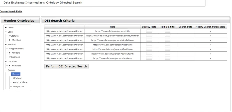
1. The DEI presents the user with a list of Ontology Web Language (OWL) classes that express the data being sought.
2. User selects one or more of the classes to be used in the search.
The use case ends.
Figure 5-3
The user has selected the Person class for an Ontology
25
Define Data Parameters
Use Case Name: Define Data Parameters.
Use Case Actors: User, Data Exchange Intermediary (DEI).
Use Case Goal: The goal of the use case is to allow the user to provide specific elements of data he or she is seeking based on the domain(s) of discourse chosen in the Define Search Universe use case.
Use Case Primary Flow:
Pre-Conditions:
1. The user must have completed the primary flow outlined in the Define Search Universe use case.
Post-Conditions:
1. The DEI is configured to perform a directed search for specific data elements.
Use Case Steps:
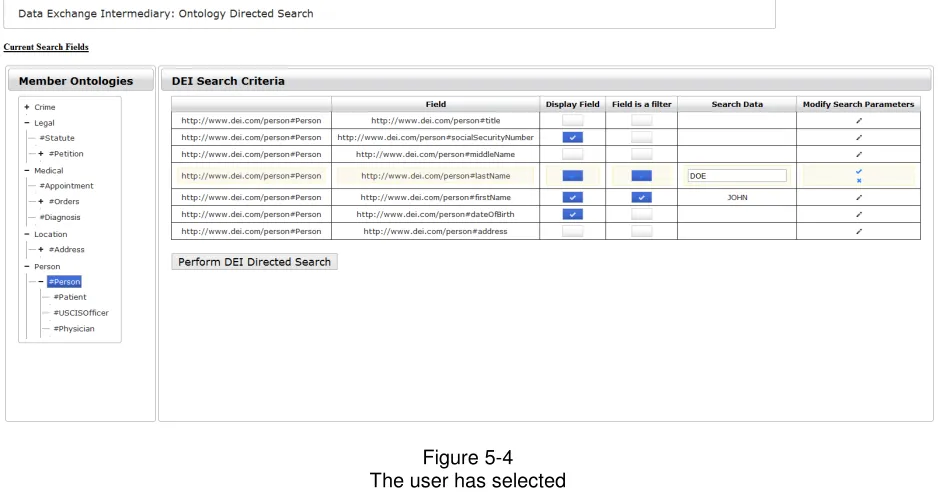
1. The use case begins with the user selecting zero or more data and/or object properties from the chosen Ontology that represents the data being sought.
2. The user specifies any filter conditions as necessary.
3. The user performs the SEARCH action outlined in the Perform DEI-Directed Search use case.
26 Figure 5-4 The user has selected
attribute and entered search criteria.
Perform DEI-Directed Search
Use Case Name: Perform DEI-Directed Search
Use Case Actors: User, Data Exchange Intermediary (DEI), DEI Middleware, Data Exchange Intermediary Partners (DEIPs)
Use Case Goal: The goal of the use case is to implement the search of the data owned by the DEIPs based on the user’s specified domain of discourse and requested data elements.
Use Case Primary Flow:
Pre-Conditions:
1. The user must have completed the primary flow outlined in the Define Search Parameters use case.
Post-Conditions:
27 Use Case Steps:
1. The use case begins with the user initializing the search request. 2. The DEI serializes the search request for network transport.
3. The DEI forwards the request to the known DEIP’s DEI Middleware. 4. The DEIP Middleware agent(s) perform the specific searches required
to implement the request.
5. The DEIP Middleware agent(s) forward the results to the DEI. 6. The DEI presents the results to the user.
The use case ends.
Figure 5-5
28
Chapter 6: Sample Architectures
Sample DEI Architectures
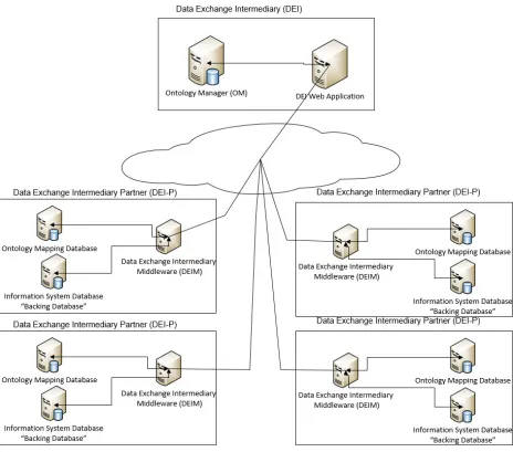
Below are two architectures that could be used to implement the DEI process within either a single, geographically dispersed organization or alternatively between separate organizations, each residing within some physically segregated networks.
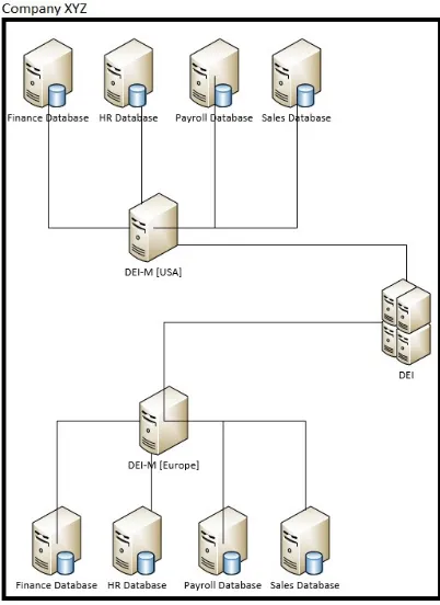
Figure 6-1
A sample DEI architecture within a single geographically dispersed organization.
Figure 6-1 depicts a potential implementation of the DEI architecture. In this
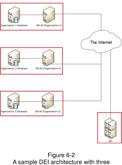
29 Figure 6-2
A sample DEI architecture with three physically separated organizations
Figure 6-2 depicts another potential implementation of the DEI architecture. In this implementation, three independent, physically separate organizations have agreed to share a subset of the datasets over which they maintain ownership. Data will be exchanged via a DEI that is also physically separated. As was the case with the example shown in figure 6-1, as long as the DEI is able to initiate network
communications with each of the DEIPs it knows about, the DEI process is able to successfully operate.
As previously mentioned in “Restrictions on Ontologies,” the DEI implementation requires the use of ontologies that provide for maximum expressiveness between user and application over the domain of data being queried. In the specific case depicted in figure 6-1, it follows that any user of the DEI implemented by Company XYZ will either be an employee of or at the very least an interested third party. This is an appropriate example of limiting the expressiveness of the DEI ontologies to concepts in reality that are pertinent to the company. On the contrary, unless each of the organizations
30
References
[1] World Wide Web Consortium (2004). OWL web ontology language overview [Abstract]. Retrieved from http://www.w3.org/TR/owl-features
[2] Government Accountability Office (2006). Information sharing (GAO Publication No. GAO-06-385). Retrieved from Government Accountability Office website:
http://www.gao.gov/new.items/d06385.pdf
[3] Oracle (2013). Oracle Database Reference 11g Release 2 (11.2) ALL_TAB_COLUMNS. Retrieved from
http://docs.oracle.com/cd/E11882_01/server.112/e25513/statviews_2103.htm
[4] Rajmohan, R., Padmapriya, N., & Jayakumar, S. (2011). A survey on problems in distributed UDDI. International Journal of Computer Applications, 36(3), p. 1-7.
[5] Singh, M., & Huhns, M. (2005). Service-Oriented Computing. Chichester: John Wiley & sons Ltd.
[6] Erl, T. (2005). Service-oriented architecture. Boston, MA: Pearson Education.
[7] Apache Jena (Version 2) [Computer Software]. Retrieved from http://jena.apache.org/download/index.html
[8] OWL API (Version 2) [Computer Software]. Retrieved from http://owlapi.sourceforge.net/index.html
[9] DARPA Information Exploitation Office (2006) DAML Ontology Library. Retrieved from http://www.daml.org/ontologies/
[10] Oracle. (2013). Enterprise Service Bus [White paper]. Retrieved from
http://www.oracle.com/technetwork/articles/soa/ind-soa-esb-1967705.html
31
[12] Department of The Navy (2012). Manual of Navy enlisted manpower and personnel classifications and occupational standards (Vol. I, pp. 1-1611). Retrieved from http://www.public.navy.mil/asnmra/corb/PEB/Documents/References/Rating%20 MOS/Navy%20Rating%20Manual%20Jan%202012/18068F%20%28Enlisted%2 9Jan12.pdf
32
Appendix A: Glossary
User: A user is defined as any entity (person and/or software) authorized to log into a specific Data Exchange Intermediary application.
Data Exchange Intermediary (DEI): The Data Exchange Intermediary is the entity that facilitates the lookup and retrieval of data from the partner systems. The DEI does not contain any data other than the definition ontologies, a list of known Data Exchange Intermediary Partners, and a list of users authorized to log in.
Data Exchange Intermediary Partners (DEIP): A Data Exchange Intermediary Partner is an organizational entity that has gone through the formal process of sharing subsets of the data under their ownership with other DEIPs by subscribing to the DEI process. DEIPs are responsible for mapping the data they wish to share with other DEIPs onto ontologies maintained by the DEI, and for suggesting new ontologies that adequately describe the content of their data sets.
Data Exchange Intermediary Middleware (DEIM): The Data Exchange Intermediary Middleware agent is the application hosted within any DEIP’s organizational
enclave/network. This application implements the user search request on a specific DEIP’s network.
Ontology Manager (OM): The Ontology Manager is an application hosted within the same network/enclave as the DEI. It is responsible for reading the flat ontology definition files and parsing them into non-flattened data objects which are provided to the DEI.
33
Appendix B: Future DEI Use Case
Use Case Name: Verify Permissions.
Use Case Actors: Data Exchange Intermediary (DEI).
Use Case Goal: The goal of the use case is to decide whether or not a specific user has permissions to view data owned by one or more DEIP(s).
Use Case Primary Flow:
Pre-Conditions:
1. The user must have completed steps (1) and (2) of the Primary Flow of the Perform DEI-Directed Search use case.
Post-Conditions:
1. The user is authorized to proceed with the request.
Use Case Steps:
1. The use case begins with the DEI determining if the user is authorized to view the requested data based on permission lists.
2. The DEI determines the user is authorized to view the requested data. 3. The use case ends.
Use Case Alternate Flow #1:
Pre-Conditions:
1. The user must have completed steps (1) and (2) of the Primary Flow of the Perform DEI-Directed Search use case.
Post-Conditions:
1. The user is not authorized to proceed with the request.
Use Case Steps:
1. The use case begins with the DEI determining if the user is authorized to view the requested data based on permission lists.
2. The DEI determines the user is NOT authorized to view the requested data.
34
Appendix C: Sample Entity Relation Diagrams
35
36
37
Vita
James Sauvinet was born in Metairie, Louisiana. He obtained his Bachelor’s degree in Computer Science from the University of New Orleans in 2010. Mr. Sauvinet was admitted to the graduate school in 2010 and studied under the direction of Dr. Shengru Tu. His graduate studies included big data, distributed systems, and database systems.