An OCL-Based Framework for Model Transformations
Duc-Hanh Dang
1,∗, Martin Gogolla
21VNU University of Engineering and Technology, Hanoi, Vietnam 2University of Bremen, Bremen, Germany
Abstract
Model transformation is an important building block for model-driven approaches. It puts forward a necessity and a challenge to specify and realize model transformation as well as to ensure the correctness of transformations. This paper proposes an OCL-based framework for model transformations. The formal foundation of the framework is the integration of Triple Graph Grammars and the Object Constraint Language (OCL). The OCL-based transformation framework offers an on-the-fly verification of model transformations and means for transformation quality assurance.
Received 06 December 2015, revised 25 December 2015, accepted 31 December 2015
Keywords: Model Transformation, OCL, Validation & Verification, Precondition and Postcondition, Invariant.
1. Introduction
Model transformation can be seen as the heart of model-driven approaches [1]. Transformations are useful for different goals such as (1) to relate views of the system to each other; (2) to reflect about a model from other domains for an enhancement of model analysis; and (3) to obtain a mapping between models in different languages. Within such cases it is necessary to offer methods to specify and realize model transformation as well as to ensure the correctness of transformations. This is really a challenge because of the diversity of models and transformations.
Problem. Many approaches to model transformation have been introduced, as surveyed in [2]. The works in [3, 4] offer mechanisms for model transformations in line with the Query/View/Transformation (QVT) standard [5]. The ideas in [6, 7] focus on the graph transformation-based approach for unidirectional transformations. Triple Graph Grammars (TGGs)
∗
Corresponding author. Email: [email protected]
are proposed in [8] as a similar approach for bidirectional transformations. In addition to specification and realization of transformations as proposed by these works, several papers discuss how to ensure the correctness of transformations. In [9] the authors introduce a method to derive Object Constraint Language (OCL) invariants from declarative transformations like TGGs and QVT in order to enable their verification and analysis. The work in [10] aims to establish a framework for transformation testing. To the best of our knowledge, so far there has not been any suitable approach yet to support both specification and quality assurance of transformations.
Contribution.(1) In this paper we focus on the integration of TGGs and OCL as a foundation for model transformation. Incorporating OCL conditions in triple rules of a triple graph grammar allows us to express better transformations. (2) Our approach targets both declarative and operational features of transformations. Within the approach a new method to extract invariants for TGG
transformations is introduced. (3) We propose a specification method of transformations and an OCL-based framework for model transformation. We realize the approach in USE [11], a tool with full OCL support. This offers an on-the-fly verification of transformations and means for quality assurance of transformations.
Outline. The rest of this paper is structured as follows. Section 2 motivates our work by means of examples. Section 3 introduces a formal foundation for specification and realization of transformations. Section 4 proposes an OCL-based framework for model transformations. Section 5 explains how the framework could offer means for transformation quality assurance. Section 6 shows how the approach is realized in the USE tool. Section 7 comments on related work. The paper is closed with a conclusion and a discussion of future work.
2. Motivating Example
We focus on a transformation situation between a statechart and an extended hierarchical automaton. A UML statechart (state machine) [12] offers a light-weight notation for describing the system behavior. In order to model-check statecharts, it is necessary to transform them and represent them in a mathematical formalism like Extended Hierarchical Automata (EHAs). EHAs have been proposed in [13] as an intermediate format to facilitate linking new tools to a statechart-based environment. This formalism uses single-source/single-target transitions (as in usual automata), and forbids interlevel transitions. The EHA notation is a simple formalism with a more restricted syntax than statecharts which nevertheless allows us to capture the richer formalism [13]. Figure 1 presents models for a traffic supervisor system for a crossing of a main road and a country road [14]. The lamp controller provides higher precedence to the main road as follow: If more than two cars are waiting at the main road (this information is provided by a sensor), the lamp will be switched from red to red-yellow immediately, instead of obeying
a waiting period as usual. A camera allows the system to record cars running illegally in the crossing during the red signal period.
The example statechart (Fig. 1) shows two basic states On and Off, reflecting whether the system is turned on or off. There is a concurrent decomposition of theOnstate. The region on the left corresponds to the lamp state, and the region on the right corresponds to the camera state. Each of these regions is concurrently active. The On state is referred to as an orthogonal state, i.e., a composite statecontaining more than one region. Note that in our specification the synchronization between the two regions currently currently is not reflected. TheOffstate, which does not have sub-states, is referred to as asimple state.
Source Restriction={Count2} Target Determination
= {Green, CameraOff} Target Determination = {Count0}
Statechart of the traffic light example
Extended Hierarchical Automata (EHA)
Fig. 1: Statechart and extended hierarchical automaton for the traffic light example. (adapted from [14])
The transformation example motivates our work with the following requirements: (1) Specifying and realizing of transformations: We need to offer means so that transformations could be specified and performed, as well as source and target models could be represented and taken as the input and output of transformations. (2) Verifying transformations: We need to check if there are any defects in a transformation. A transformation can be considered as a program taking the source and target model as the input and output. We could expect several reasonable assumptions on such a transformation model to be satisfied. (3) Validating transformations: The aim is to ensure a transformation is a “right” one by executing the transformation in various scenarios and comparing the de facto result with the expected outcome. The process cannot be fully automated: The modeler has to define relevant scenarios, so-called test cases, and then to compare the obtained and expected result.
3. Foundations for a Model-Driven Approach
This section explains foundations for a model-driven approach to software engineering.
3.1. Graph Transformation
Definition 1 (Graphs and Morphisms). Let a set of labels L be given.A directed, labeled graph is a tuple G=(VG,EG,sG,tG,lvG,leG), where
• VGis a finite set of nodes (vertices),
• EG⊆VG×VGis a binary relation describing
the edges,
• sG,tG : EG → VG are source and target
functions mapping graph edges to nodes, and
• lvG : VG → L and leG : EG → L are
functions that assign a label to a node and an edge, respectively.
A graph is said to be empty, if the VG and EG
are empty sets.
Let two directed, labeled graphs G = (VG,EG,sG,tG,lvG,leG) and H =
morphism f : G → H is a pair (fV,fE), where
fV :VG→VH, fE :EG→EHpreserves sources,
targets, and labels, i.e., fV ◦ sG = sH◦ fE and
fV ◦tG=tH◦ fE.
G H
a:X
b:Y
c:Y p
q c1:Y
b1:Y
d:Z a1:X
t
s v
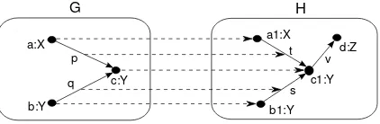
Fig. 2: Two directed, labeled graphsGandHand a graph morphismG→H(informally speaking,HcontainsG).
Figure 2 shows two directed, labeled graphs G and H and a graph morphismG → H. The mapping is represented by dashed lines between the nodes and edges ofGandH.
Triple graph grammars (TGGs) have been proposed as a means to specify bidirectional translations between graph languages. Integrated graphs obtained by triple derivations are called triple graphs.
Definition 2 (Triple Graphs and Morphisms).
Three graphs SG, CG, and TG, called source, connection, and target graph, together with two graph morphisms sG : CG → SG
and tG : CG → TG form a triple graph
G = (SG ←sG CG →tG TG). G is said to be empty, if SG, CG, and TG are empty graphs. A triple graph morphism m = (s,c,t) : G → H between two triple graphs G = (SG ←sG CG →tG TG) and H = (SH ←sH CH →tH TH)consists of three graph morphisms s : SG → SH, c : CG → CH and t : TG → TH such that s◦ sG = sH ◦c and
t◦tG = tH◦c. It is injective, if the morphisms s,
c and t are injective.
Figure 3 shows a triple graph containing a statechart together with correspondence nodes pointing to the extended hierarchical automata (EHA). References between source and target models denote translation correspondences.
:Statechart
refined eha:EHA s2e:SC2EHA
c2s1:S2SH
s2a1:St2Aut
c2s2:S2SH
s2a2:St2Aut
onStateH:StateH
name = 'On'
lampAut:Automata
name = 'Lamp'
redStateH:StateH
name = 'Red'
counterAut:Automata
name = 'Red'
onState:CompState
isConcurr=true name='On'
lampState:CompState
isConcurr=false name='Lamp'
redState:CompState
isConcurr=false name='Red'
owner owner owner
container refined
owner owner
container
container
eha sc
Fig. 3: Triple graph for an integrated SC2EHA model.
Definition 3 (Triple Graph Grammar).
A triple rule tr =L→tr Rconsists of triple graphs
LandRand an injective triple morphisms tr.
(SL
(SR
CL
CR
TL)
TR)
t s
sR tR
tL sL
L =
R =
tr c
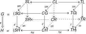
An application of a triple rule tr = (s,c,t) : L→R to a given triple graph G to yield a triple graph H consists of the following steps:
• Choose an occurrence of the LHS L in G by defining a triple graph morphism m = (sm,cm,tm) :L→G, called atriple match.
• Glue the graph G and the RHS R according to the occurrences of L in G so that new items that are presented in R but not in L are added to G. This yields a gluing graph Z. Formally, we have m(L∩R) = G∩Z. Here, graphs can be seen as a set of items including vertices and edges.
• Remove the occurrence of L from Z as well as alldangling edges, i.e., all edges incident to a removed node. This yields the resulting graph H. Formally, we have H=Z\m(L).
• The gluing step allows us to obtain the so-called comatch morphism n = (sn,cn,tn), where sn=SR→SH, cn=CR→CH, and tn = TR → TH. The induced morphisms sH : CH → SH and tH :CH → TH could
(SG
(SH
CG
CH
TG)
TH)
t’ s’
sH tH
G =
H =
tr
SL
SR
CL
CR
TL
TR
tm sm
c’ cm
tn
sn cn
A triple graph grammar is a structure TGG = (TG,S,TR) where TG includes a so-called triple type graph and a typing function mapping so-called typed graphs to the type graph, S is an initial graph, and TR = {tr1,tr2, ....,trn} is a set
of triple rules. Triple graph language of TGG is the set {G | G is typed by TG∧ ∃ triple graph transformationS ⇒∗G}.
{new}
{new}
{new} {new}
{new}
Fig. 4: Triple rule for the SC2EHA transformation. Figure 4 is part of a triple graph grammar that generates statecharts and corresponding EHA models. This rule may create a simple state of a statechart and its corresponding state of the corresponding EHA model at any time.
Such an integrated triple graph is often defined by a triple derivation. Derived triple rules allows us to compute the triple graph by taking the source (target or both) model as the input. A detailed explanation of how to apply derived triples is shown in SubSect. 3.5.
Definition 4 (Derived Triple Rules). Each triple rule tr = L → R derives forward, backward, and integration rules as follows:
(SR
(SR CL
CR TR)
TR) integration rule trI
c id
sR tR
t o tL
(SR
(SR CL
CR TL)
TR) forward rule trF
t
c
id
sR tR
tL s o sL
(SL
(SR CL
CR TR)
TR) backward rule trB
s c id
sR tR
sL t o tL
id s o sL
where id is the identify function.
3.2. The Object Constraint Language
The Object Constraint Langauge (OCL) [15] is a formal language to describe expressions on UML models, e.g., as shown in Fig. 5: (1) OCL expressions, that might be object constraints or queries, do not have side effects. (2) The OCL is a typed language. Each valid (well-formed) OCL expression has a type, which is the type of the evaluated value of this expression. The type system of OCL includes basic types (e.g., Integer, Real, String, and Boolean), object types, collection types (e.g., Collection(t), Set(t), Bag(t), and Sequence(t) for describing collections of values of typet), and message types. (3) OCL is often employed for the following purposes:
Fig. 5: Object model visualized by a class diagram.
• To specify invariants, i.e., conditions that must be true for all instances of the class in all system states. Example:
-- The number of cars is -- greater than 10.
context CarModel inv: self.car.size() > 10
• To describe pre- and post conditions on operations.
-- When a car is picked up.
context Rental::assignCar(cr:Car)
pre self.car = null
post self.car = cr
• To describe guards within a statechart.
OCL expressions are developed on the basis of an object model. The aim is to allow us to express attribute values and logic conditions on the structure defined by the object model. Specifically, the object model structure is extended with an OCL algebra [16].
Definition 5 (Object Models).
An object model is the structure
M=(CLASS,ATTc,OPc,ASSOC,associates, roles,multiplicities,≺)where
1. CLASS⊆ N is a set of names representing a set of classes, whereN ⊆ A+is a non-empty set of names over alphabet A. Each class c ∈ CLASSinduces an object type tc ∈ T .
The values of the type refer to the objects of the class.
2. ATTcis the attributes of a class c∈CLASS,
defined as a set of signatures a : tc → t,
where the attribute name a is an element of
N, tc ∈T is the type of class c, and t∈T is
the type of the attribute.
3. OPc is a set of signatures for user-defined
operations of a class c with type tc ∈T . The
signatures are of the formω : tc×t1×...×
tn→t, whereωis the name of the operation,
and t, t1, ... , tnare types in T .
4. ASSOCis a set of association names. (a) associates : ASSOC → CLASS+ is a function mapping each association name to a list of participating classes. This list has at least two elements.
(b) roles : ASSOC → N+ is a function mapping each association to a list of role names. It assigns each class participating in an association a unique role name. (c) multiplicities : ASSOC → P(N0)+
is a function mapping each association to a list of multiplicities. It assigns each class participating in an association a multiplicity. A multiplicity is a non-empty set of natural numbers (an element of the power setP(N0)+) different from{0}.
5. ≺is a partial order onCLASSreflecting the generalization hierarchy of classes.
Figure 5 visualizes an object model in the form of a UML class diagram.
An interpretation of an object model is referred to as a snapshot (a system state). A snapshot is constituted by objects, links, and attribute values.
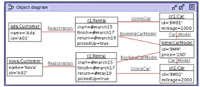
Fig. 6: A snapshot visualized by an object diagram.
Definition 6 (Snapshots). A snapshot of an object modelMis the structure
σ(M)=(σCLASS, σATT, σASSOC)such that:
1. For each c ∈ CLASS, the finite set
σCLASS(c) contains all objects of class
c ∈ CLASS existing in the snapshot:
σCLASS(c)⊂oid(c).
2. Functions σATT assign attribute values for
each object in the state. σATT(a) :
CLASS(c)→I(t)for each a:tc→ATT∗c.
3. For each as ∈ ASSOC, there is a set of current links: σASSOC(as) ⊂ IASSOC(as). A link set must satisfy all multiplicity specifications: ∀i ∈ {1, ...,n},∀l ∈ σASSOC(as): |{l0|l0 ∈ σASSOC(as)∧(πi(l0) =
πi(l))}| ∈πi(multiplicities(as))
where
• I(t)is the domain of each type t∈T .
• oid(c)is the objects of each c∈CLASS. The set is often infinite. ICLASS(c) = oid(c) ∪ {oid(c0)|c0 ∈CLASS∧c0 ≺c}.
• ATT∗cis the direct and inherited attributes of the class c:ATT∗c =ATTc∪c≺c0 ATTc0.
• IASSOC(as) = ICLASS(c1)× ...× ICLASS(cn)
interprets the association as, where associations(as) = hc1,c2, ...,cni,
as ∈ ASSOC, and c1,c2, ...,cn are the
classes. Each las∈IASSOC(as)is a link.
Figure 6 visualizes a snapshot in the form of a UML object diagram. The snapshot is the interpretation of the object model shown in Fig. 5.
3.3. Models and Metamodels
Amodelis a representation in a certain medium of something in the same or another medium. The model captures the important aspects of the thing being modeled from a certain point of view and simplifies or omits the rest [12]. The medium to express models, a convenience for working, can be 3-D figures in a paper, a computer for models of buildings, or modeling languages. Our work focuses on modeling languages, defined using metamodels, as the means to express models.
Definition 7 (Metamodels). A metamodel is the structure MM = (M,WFC) where the M is an object model and the WFC is a set of OCL conditions, so-called well-formedness conditions, w.r.t the OCL algebra built on theM.
State
name:String
Statechart
trOwner
Transition * * *
src 0..1 owner
*
dst
* *trigger 0..1
1 1
Metamodel - Type graph
On Off
Switch
Model in concrete syntax
:State
name = 'Off'
:State
name = 'On'
:Statechart
:Event
name = 'Switch'
Event
name:String
:Transition
Model in abstract syntax - Typed graph
src
dst owner
owner trOwner
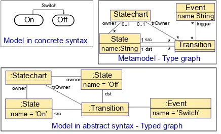
Fig. 7: The simplified metamodel for statechart models. Figure 7 shows a simplified metamodel for statecharts. The graph corresponding to the metamodel is referred to as a type graph. The object model M includes 4 classes (Statechart, State, Transition, and Event) and 5 associations. The W FC includes the invariant ownsChildState, “Every child state of a composite state belongs to the same statechart with the parent state.”
context Statechart inv ownsChildState: self.state->forAll(p:State|
if p.oclIsTypeOf(CompState) then
p.oclAsType(CompState).content->
forAll(c:State|self.state->includes(c)) else true endif)
Definition 8 (Models). Let a metamodelMM = (M,WFC) be given. A model that conforms to the metamodel MM is a snapshot of theMand the snapshot fulfills all the OCL invariants of theWFC.
Figure 7 shows a model that conforms to the statechart metamodel. The graph corresponding to the model is referred to as a typed graph. The model might be represented in different forms, i.e., in abstract syntax or concrete syntax.
3.4. Incorporation of OCL and Triple Rules
Within the context where the underlying type graph represents a metamodel, we could employ OCL conditions in order to restrict the applicability of triple rules. The aim is to increase the expressiveness of triple rules. For example, with the rule shown in Fig. 3, we could attach it with the OCL precondition cps.isConcurr = f alse and the postcondition s.name <> null ∧
aut1.name <> null. We could define OCL application conditions for triple rules as follows.
Definition 9 (OCL Application Conditions).
OCL application conditions (BACs1) of a triple rule consist of OCL conditions in source, target, and correspondence parts of the triple rule. BACs within the LHS and RHS of the triple rule are pre- and postconditions, respectively:
• BACpre= BACS L∪BACCL∪BACT L,
• BACpost=BACS R∪BACCR∪BACT R, and
• BAC=[BACpre,BACpost],
where the BACxy with xy ∈ {‘S L0,‘S R0,‘CL0,‘CR0,‘T L0,‘T R0} are the BACs in the LHS and RHS of the source, correspondence, and target parts of the triple rule, respectively; the BACpre and BACpost are
the pre- and postconditions, respectively.
Definition 10 (Application Condition Fulfillment).
A triple rule with BACs is a tuple tr = (L,R,BAC), where BAC includes OCL application conditions. A triple graph H is derived from a triple graph G by a triple rule tr=(L,R,BAC)and a triple match m iff:
• H is derived by(L→R,m)and
• BAC is fulfilled in the application G⇒r H,
where r :L →R is the rule which is obtained by viewing the triple graphs LHS and RHS of the tr rule as plain graphs.
Definition 11 (Restrictions on Derived Rules).
Let a triple rule tr be given. The preconditions of its derived triple rules are defined as follows.
• BACtrFpre= BACtrS R∗∪BACtrCL∪BACtrT L,
• BACtrBpre= BACtrS L∪BACtrCL∪BACtrT R∗, and
• BACtrIpre= BACtrS R∗∪BACtrCL∪BACtrT R∗
The postconditions are defined as follows.
• BACtrFpost=BACS Rtr ∗∪BACCRtr ∪BACtrT R,
• BACtrBpost=BACS Rtr ∪BACtrCR∪BACT Rtr ∗, and
• BACtrIpost=BACS Rtr ∗∪BACCRtr ∪BACtrT R∗,
where
• BACtrFpre, BACtrBpre, and BACtrIpre are the precondition of derived rules for forward, backward, and integration transformation, respectively; BACtrFpost, BACtrBpost, and BACtrIpostare the postconditions,
• BACtrxy with xy ∈
{‘S L0,‘S R0,‘CL0,‘CR0,‘T L0,‘T R0} are BACs in the LHS and RHS of parts of the triple rule tr, respectively, and
• BACtrS R∗, BACCRtr ∗, and BACT Rtr ∗ are BACs excepting ones with ‘@pre’ in S R, CR, and T R , respectively.
3.5. Model Transformations
The aim of TGGs is to ease the description of complex transformations. Structural mappings within triple rules allow us to relate the source, target, and correspondence parts within a triple derivation: Once a plain rule derivation for the source (or target) model is given, we can induce two derivations corresponding to the remaining parts. In this way operational scenarios of triple rules for model transformations are defined.
Let TGG = (TG,S,TR) be a triple graph grammar incorporating OCL. Let VL be the language of TGG, and VLs, VLc, and VLt
be the source, correspondence, and target language as the result of the projection onto the source, correspondence, and target part of VL, respectively.
Definition 12 (Forward Transformation).
Let a graph GS ∈ VLs be given. A forward
transformation from GS to GT is a computation
to define the graph GT ∈ VLt through a triple
derivation S ⇒∗ (GS ←GC→GT).
Definition 13 (Backward Transformation).
Let a graph GT ∈ VLt be given. A backward
transformation from GTto GS is a computation to
define the graph GS ∈ VLs through a derivation
S ⇒∗ (GS ←GC →GT).
Definition 14 (Model Integration). Let the graphs GS ∈ VLt and GT ∈ VLs be given. A
model integration of GS and GT is a computation
to define a derivation S ⇒∗ (GS ←GC →GT).
Definition 15 (Model Co-Evolution). Let ES ∈
VLs and ET ∈ VLt be graphs as source and
target parts of a triple graph E, respectively. A model co-evolution from (ES,ET) to (FS,FT) is
a computation to define graphs FS ∈ VLs and
FT ∈ VLt through the derivation (ES ← EC →
ET) ∗
⇒(FS ←FC→FT).
Theorem 1 (Derived Rules for Transformations).
We could obtain the forward transformation from GS to GT, i.e., S
∗
⇒ (GS ← GC → GT), as the
following conditions are fulfilled.
(i) (GS ←SC → ST) trF1,m1
=⇒ . . .trF=⇒n,mn (GS ←
GC → GT), where mi = (smi,cmi,tmi) are
triple matches.
(ii) ∀i > 0,0 < j < i, snj(SRtrj \ SLtrj) ∩
sni(SRtri \SLtri) = ∅, where (sni,cni,tni) is
the comatch of mi.
Proof. Suppose that at the ith step of the transformation in (i), we can define the triple
graphGi such that S = (SS ← SC → ST) tr1,m1
=⇒
. . . tri,mi
=⇒ Gi = (GiS ← GCi → GiT) and G1 ⊂
G2. . . ⊂ Gi ⊂ GS. Now at the i + 1th step
of the transformation in (i), we have (GS ←
GiC → GiT) trF=i+⇒1,mi+1 (GS ← GiC+1 → GiT+1).
Then, the condition (ii) allows us to defineGi+1 such that Gi ⊂ Gi+1 ⊂ GS and Gi = (GiS ←
GCi → GiT) tri+=1⇒,mi+1 Gi+1 = (GiS+1 ← GCi+1 →
GiT+1). Therefore, by indution there exists a
transformation S = (SS ← SC → ST) tr1,m1
=⇒
. . . trn,mn
=⇒ Gn = (GS ←GC →GT). This is what
we need to prove.
For backward and integration transformation, we can obtain a similar result. The condition (ii) in these cases is shown respectively as follow.
(SS ←SC→GT)
trB1,m1
=⇒ . . .trB=⇒n,mn(GS ←GC →GT),
(GS ←SC→GT)
trI1,m1
=⇒. . .trI=n⇒,mn(GS ←GC→GT).
{new}
{new} {new}
{new}
Fig. 8: A forward transformation step by the forward rule derived from the rule shown in Fig. 4.
Figure 8 shows a transformation step for the forward transformation from a statechart to an
EHA model. The forward rule is derived from the rule shown in Fig. 4.
4. A Transformation Model in OCL
This section focuses on the operational scenarios derived from triple rules including OCL. We employ OCL in order to realize the operational scenarios of triple rules towards an OCL-based framework for model transformation. The OCL framework also offers a new operation for model synchronization.
4.1. Basic Idea
As illustrated in Fig. 9, we consider each transformation scenario derived from a triple rule as a special kind of model behavior, namely behavior of operations. Each transformation scenario can be mapped to an operation. We realize the operations by taking two views on them: Declarative OCL pre- and postconditions are employed as operation contracts, and imperative OCL command sequences are taken as an operational realization.
4.2. OCL Transformation Operations
Figure 10 depicts the input of transformation operations derived from triple rules. We use a sheet including six cells that correspond to six patterns of the original triple rule in order to describe the input of each operation. The cell denoted by ‘I’ means that nodes in this part belong to the input of the operation. The cell denoted by ‘?’ represents objects created by the operation. The cell denoted by ‘U’ means that part of this cell belongs to the input of the operation, and this part can be updated by the operation. The remaining nodes in this cell correspond to objects created by the operation.
Operational Scenarios Input/Computing
Forward Transformation
Model Integration
Model Synchronization
Model Co−Evolution I I I
? ? ?
I I I
I ? ?
I I I
I ? I
I I I
U I U
SL CL TL
SR CR TR
I: Input
U: Update ?: Create
maskS=SR\SL
maskT=TR\TL maskC=CR\CL
Fig. 10: The input and computation for derived triple rules.
−−−−−−−−−−−−−−−−−−−−−−−−−−−−−−−−−−−−−−Model Co−Evolution compStateNest_coEvol(
matchSL:Tuple(sc:Statechart,cps:CompState,_s_name:String), matchTL:Tuple(eha:EHA,aut:AutH,_aut1_name:String), matchCL:Tuple(s2e:SC2EHA,s2a:St2Aut))
−−−−−−−−−−−−−−−−−−−−−−−−−−−−−−−−−−−−−−Forward Transformation compStateNest_forwTrafo(
matchSR:Tuple(s:CompState,sc:Statechart,cps:CompState), matchTL:Tuple(eha:EHA,aut:AutH,_aut1_name:String), matchCL:Tuple(s2e:SC2EHA,s2a:St2Aut))
−−−−−−−−−−−−−−−−−−−−−−−−−−−−−−−−−−−−−−Model Integration compStateNest_integraTrafo(
matchSR:Tuple(s:CompState,sc:Statechart,cps:CompState), matchTR:Tuple(sH:StateH,aut1:AutH,eha:EHA,aut:AutH), matchCL:Tuple(s2e:SC2EHA,s2a:St2Aut))
−−−−−−−−−−−−−−−−−−−−−−−−−−−−−−−−−−−−−−Model Synchronization compStateNest_synchTrafo(
matchSL:Tuple(sc:Statechart,cps:CompState,_s_name:String), matchTL:Tuple(eha:EHA,aut:AutH,_aut1_name:String), matchCL:Tuple(s2e:SC2EHA,s2a:St2Aut),
maskS:Tuple(s:CompState), maskT:Tuple(sH:StateH,aut1:AutH), maskC:Tuple(s2sH:S2SH,s2a1:St2Aut))
RuleCollection
Fig. 11: Transformation operations derived from the triple rulecompStateNestshown in Fig. 4.
Figure 11 presents the derived operations w.r.t the triple rule depicted in Fig. 4. Note that when an entry of a mask parameter (maskS,
maskT, or maskC having the Tuple type) in a synchronization operation is undefined, a new object corresponding to this entry is newly created. Otherwise, the entry will be updated.
4.3. Example Transformation Scenarios
We have defined 9 triple rules for the SC2EHA transformation as summarized in Table 1. We illustrate transformation scenarios by explaining informally a transformation step of each scenario. These example transformation steps are performed by operations derived from the triple rule shown in Fig. 4.
4.3.1. Forward Transformation
The transformation step for the forward transformation from the statechart to the EHA is illustrated as shown in Fig. 8. The match for this application includes objects highlighted in the first object diagram. The part (objects, nodes) which is newly created includes objects highlighted in the second object diagram. This means that all nodes and links in the source side of the original rule (Fig. 4) are used for matching the derived triple rule.
Table 1: Triple rules for the SC2EHA transformation
Triple rule Effect on statechart Effect on EHA
initTop to create the initial state, a simple state, and the transition between them, e.g., to create theOffstate.
to create the top state, the top automaton, and its initial state, e.g., to create the initial stateOff.
initNest to create the initial pseudo state, a simple state, and the transition between them, e.g., to create the state Green.
to create the initial state of the non-top automaton, e.g., to create the initial stateGreen.
simpStateNest to create a simple state as the child of a composite state, e.g., to create the stateYelloworCount1.
to create a simple state as the child of an automaton, e.g., to create the state YelloworCount1.
concurrStateTop to create a concurrent state at the top level, e.g., to create theOnstate.
to create a state (e.g., theOnstate) of the top automaton and the automatons corresponding to the regions of the composite state. These automatons refine the state.
compStateNest to create a non-concurrent composite state as a child of a composite state, e.g., to create theRedstate.
to create a state and an automaton refining the state, e.g., to create the Redstate and the automaton refining this state.
transitToSimp to create a non-interlevel transition to a simple state, e.g., to create the transition fromGreentoYellow.
to create a transition in an automaton, e.g., to create the transition from GreentoYellow.
transitToConcurr to create a non-interlevel transition to a concurrent state, e.g., to create the transition fromOfftoOn.
to create a transition to a state that is refined by automatons. This transition is labeled with the target determination set. For example, to create the transition fromOfftoOn.
transitToComp to create a non-interlevel transition to a non-concurrent composite state, e.g., to create the transition from YellowtoRed.
to create a transition together with labels for the target determination set, e.g., to create the transition from Yellow to Red and its target determination set.
transitUpSimp to create an interlevel transition up to a state at the next level, e.g., to create the transition from Count2to RedYellow.
4.3.2. Model Integration
The transformation step to integrate the example statechart and the example EHA is shown as in Fig. 12. We recognize that new parts occur only in the correspondence part. The match for this application includes all nodes and links in the source and target sides of the original rule.
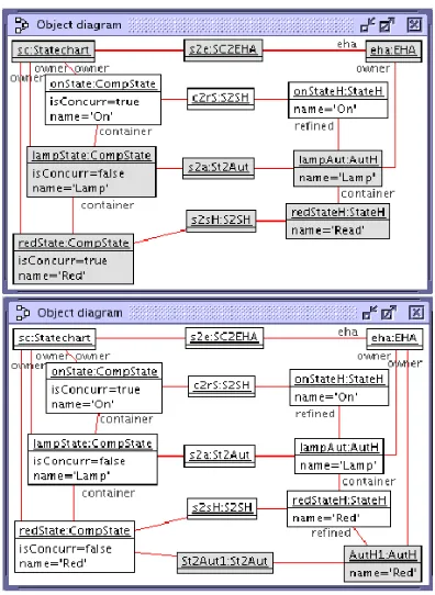
4.3.3. Model Synchronization
Figure 13 shows the transformation step to integrate the statechart and the EHA. The effect of the so-called synchronization step includes: (1) two objects highlighted in the second object diagram are created, and (2) thenameattribute of theredStateHobject is updated.
Fig. 13: Example model synchronization step.
5. Quality Assurance of Transformations
This section discusses how our OCL-based transformation framework offers means for transformation quality assurance.
5.1. Verification of Transformation
We explain it in a formal way: Let MMS
and MMT be metamodels for source and target
models, respectively. LetTGTS=(TG,S,TR) be a TGG, which relates source and target models to each other. Forward operations allows us to define a corresponding target modelMT for each
source model MS. We need to check if the
target model MT is correctly defined. Note that
the verification for other transformation scenarios can be similarly obtained.
5.1.1. Check Invariants of Transformations Triple rules can be viewed as templates establishing mappings between source and target models. Therefore, the transformation is correct only if such mappings conform to triple rules. For example, with the triple rule shown in Fig. 4 a mapping that conforms to the rule must include 11 objects and 14 links. For the check we aim to maintain “traces” for such mappings. We propose to add a new node into the correspondence part of each rule. The new node represents an instance of a class whose name coincides with the rule name. The node is linked to all nodes in the correspondence part so that from this node we can navigate to them within an OCL expression. We can define an OCL condition to represent the pattern of this rule. For example, the following OCL invariant of theCompS tateNest class represents the rule CompS tateNest shown in Fig. 4. The transformation is correct only if such an invariant are valid.
context CompStateNest inv isMatch: let s2e:SC2EHA = self.s2e in let s2a:St2Aut = self.s2a in let s2sH:S2SH = self.s2sH in let s2a1:St2Aut = self.s2a1 in s2e.isDefined and s2a.isDefined and s2sH.isDefined and s2a1.isDefined and s2e.includes(sc) and s2e.includes(eha) and s2a.includes(cps) and s2a.includes(autH) and s2sH.includes(s) and s2sH.includes(sH) and s2a1.includes(s) and s2a1.includes(aut1) and s2a.aut.includes(sH) and s2a.aut.includes(eha) and s2a1.aut1.includes(sH) and
5.1.2. Check Contract Fulfillment
A forward transformation is realized as a sequence of OCL operation applications: dtr :
(MS ← φ→φ) trF1,m1
=⇒ . . . trF=⇒n,mn (MS ← MC →
MT), where trFi are forward rules and mi are
triple matches. In order to check the correctness of the transformation we check if each operation application realizes correctly a rule application. By checking the contract of the operation, i.e., a pair of pre- and postconditions it allows us to ensure the correctness of the transformation step. It offers an on-the-fly verification for different transformation properties.
5.1.3. Check Model Properties
The declarative language OCL allows us to navigate and to evaluate queries on models. Therefore, we can employ OCL to express properties of models at any specific moment in time. For example, the following OCL condition expresses the property“There is a transition from the ‘Red’ state to the ‘Yellow’ state.”
Trans.allInstances()->exists(t| t.src.name=’Red’ and
t.dst.name=’Yellow’)
5.1.4. Check Well-formedness of Models The transformation with triple rules may maintain the conformance relationship between a model as a typed graph and its metamodel as a type graph. However, when the metamodel is restricted by OCL conditions, models during a transformation may no longer conform to their metamodel. A model conforms to the metamodel, i.e., it is well-formed only if such restricting invariants are fulfilled. For example, during the SC2EHA transformation, the following invariant ownsChildState needs to be valid. The invariant expresses the condition “Every child state of a composite state belongs to the same statechart with the parent state.”
context Statechart inv ownsChildState: self.state->forAll(p:State|
if p.oclIsTypeOf(CompState) then p.oclAsType(CompState).content->
forAll(c:State|self.state->includes(c)) else true endif)
5.2. Validation of Transformation
This section focuses on features of the OCL-based transformation framework that might provide support for a semi-automated solution to validate transformations.
5.2.1. Model Integration for Test Cases
Given a test case including the source model MS and the expected target modelMT. To check
the transformation with the test case means we check if MT coincides with the resulting model
M0T. Instead of this, we could employ integration rules in order to obtain an integration of MS
and MT: A mapping between these models is
established. The derivation is such that (MS ← φ → MT)
trI1,m1
=⇒ . . . trI=n⇒,mn (MS ← MC → MT),
where trIi are integration rules andmi are triple
matches. In this way the transformation can be better animated for the modeler.
5.2.2. Animation of Transformation
After each transformation step, we can see the combination of the source, correspondence, and target part as a whole model. We could employ OCL expressions in order to explore such a model. Mappings within the current rule application can be highlighted by OCL queries. This makes it easier for the modeler to check if the rule application is correct.
6. The RTL Language and Tool Support
Our approach for verification and validation of transformation is realized with the support of USE [11], which is a tool for analysis, reasoning, verification and validation of UML/OCL specifications. We define the RTL2 language in order to specify triple rules incorporating OCL. The declarative specification in textual form can generate the different operations for transformation scenarios as illustrated in Fig. 14.
With the full OCL support, USE allows us to realize transformations and to ensure their correctness as discussed in Sect. 5: We could
check class invariants, pre- and postconditions of operations, and properties of models, which are expressed in OCL. In USE system states are represented as object diagrams. System evolution can be carried out using operations based on basic state manipulations, such as (1) creating and destroying objects or links and (2) modifying attributes. In this way a transformation framework based on the integration of TGGs and OCL are completely covered by USE. Figure 15 shows metamodels for the SC2EHA transformation in USE.
co nt ext R ule Co lle ct ion :: sim pS tat eTo p_ coE vo l( ma tch SL :Tu pl e(s c: Sta te cha rt ,_s _na me :St ri ng) , ma tch TL :Tu pl e(e ha :EH A, aut :A utH ), ma tch CL :Tu pl e(s 2e :SC 2E HA) ) pr e sim pS tat eT op_ co Evo l_ pre : -- - -- - -- - -- - -- - -- - -- - -- - --ma tch SL :Tu pl e(s c: Sta te cha rt ,_s _na me :St ri ng) le t s c: St at ech ar t = m atc hS L.s c i n le t _ s_ nam e: Str in g = m atc hS L._ s_n am e i n -- - -- - -- - -- - -- - -- - -- - -- - --ma tch TL :Tu pl e(e ha :EH A, aut :A utH ) le t e ha : E HA = ma tch TL .eh a in le t a ut : A ut H = m atc hT L.a ut in -- - -- - -- - -- - -- - -- - -- - -- - --ma tch CL :Tu pl e(s 2e :SC 2E HA) le t s 2e : S C2 EHA = ma tc hCL .s 2e in --S_p re con di tio n --T_p re con di tio n eha .a utH -> inc lu des Al l(S et {au t}) a nd aut .r efi ne d=e ha .to p and --C_p re con di tio n Set {s 2e. sc }-> in clu de sAl l( Set {sc }) an d Set {s 2e. eh a}->i ncl ud esA ll (Se t{e ha }) po st si mp Sta te Nes t_ coE vo l_p os t: rul e sim p S ta te T o p che ckS ou rce( sc:S ta te char t
){ s:S
im pS tate (sc,s):OwnsS tate [s. n am e<>o clU nd efin ed (S tr ing )] [s. co ntai ner =o clU nd efin ed (Co m pS tate) ] }che ckT a rge t( e ha:E HA
aut:AutH (eh
a,au t) :O w nsA u tH [au t.r efine d=e ha .top ]
){ sH:StateH (au
t,sH) :Co ntai nsS tateH }che ckCo rr ( (sc,eha ) a s (sc,eh a) in s2 e:S C2 E HA ){ (( S ta te )s, sH ) a s (sc,eh a) in s2 sH:S 2S H S 2S H :[sel f.eh a.na m e=se lf. sc.na m e] }end (a) r ul e spe cifica ti on i n R TL (b) t h e ge ne rated o pe ratio n f o r co -evo lu ti on
Fig. 14: RTL specification and generated OCL operations.
7. Related Work
Triple Graph Grammars (TGGs) have been proposed in [8]. Since then, many works have extended TGGs for software engineering [17]. Here we focus on the incorporation of TGGs and OCL as a foundation for transformations as proposed in our previous work [18, 19, 20]. This
work is an extended version of our previous work with a focus on a formal foundation and an OCL-based framework for model transformations.
Many approaches have been proposed for model transformation. Most of them are in line with the standard QVT [5] such as ATL [3] and Kermeta [4]. Like our work, they allow the developer to precisely present models using metamodels and OCL. The advantage of our approach is that it is based on the integration of TGGs and OCL, which allows the developer to automatically analyze and verify transformations, and supports for bidirectional model transformation.
Our approach for model transformation is based on graph transformation like the work in VMTS [6] and Fujaba [17]. Many other works focus on the translation of the transformation to a formal domain for model checking such as Alloy in [21], Promela in [22], and Maude in [23].
Fig. 15: Metamodels for the SC2EHA transformation.
8. Conclusion
We have introduced an approach for specifying, realizing, and ensuring the quality of model transformations: (1) The foundation of the approach is based on the integration of TGGs and OCL. We have further formulated operation contracts for derived triple rules in order to realize them as OCL operations with two views: Declarative OCL pre- and postconditions are employed as operation contracts, and imperative command sequences are taken as an operational realization. (2) Both declarative and operational views are obtained by an automatic translation from the RTL specification of transformations. This work also embodies a new method to extract invariants for transformations. The central idea is to view transformations as models. (3) An OCL-based framework for model transformation has been established. As being realized on a full OCL support environment like USE, the framework offers a support for validation and verification of transformations.
Our future work includes the following issues. We aim to enhance the technique to extract invariants for transformation models. A control structure like sequence diagram for the RTL specification is also in the focus of our future work. The goal is to increase the efficiency of transformations. The technique to generate test cases from the RTL specification will also be explored. We will focus on other properties of transformations such as the determinateness of transformation. These are efforts towards a full framework for quality assurance of model transformations. Larger case studies must give detailed feedback on the proposal.
Acknowledgement
References
[1] S. Sendall, W. Kozaczynski, Model Transformation: the Heart and Soul of Model-Driven Software Development, IEEE Software 20 (5) (2003) 42– 45. [2] T. Mens, P. V. Gorp, A taxonomy of model
transformation, Electronic Notes in Theoretical Computer Science 152 (2006) 125 – 142.
[3] F. Jouault, F. Allilaire, J. Bzivin, I. Kurtev, ATL: A Model Transformation Tool, Science of Computer Programming 72 (1-2) (2008) 31–39.
[4] P.-A. Muller, F. Fleurey, J.-M. Jzquel, Weaving Executability into Object-Oriented Meta-languages, in: Proc. 8th. Int. Conf. Model Driven Engineering Languages and Systems (MODELS), Vol. 3713, Springer Berlin, 2005, pp. 264–278.
[5] OMG, Meta Object Facility (MOF) 2.0 Query/View/Transformation Specification, Final Adopted Specification ptc/07-07-07, OMG, 2007. [6] L. Lengyel, T. Levendovszky, H. Charaf, Validated
Model Transformation-Driven Software Development, Int. J. Comput. Appl. Technol. 31 (1/2) (2008) 106– 119.
[7] D. Varr, A. Pataricza, Automated Formal Verification of Model Transformations, in: J. Jrjens, B. Rumpe, R. France, E. B. Fernandez (Eds.), Proc. 3rd Workshop on Critical Systems Development in UML (UML/CSDUML), Technische Universitt Mnchen, 2003, pp. 63–78.
[8] A. Schrr, Specification of Graph Translators with Triple Graph Grammars, in: M. Schmidt (Ed.), Proc. 20th Int. Workshop on Graph-Theoretic Concepts in Computer Science (WG), Vol. 903 of LNCS, Springer-Verlag, 1995, pp. 151–163.
[9] J. Cabot, R. Claris, E. Guerra, J. d. Lara, Verification and Validation of Declarative Model-to-model Transformations Through Invariants, Journal of Systems and Software 83 (2) (2010) 283–302. [10] Y. Lin, J. Zhang, J. Gray, A Framework for Testing
Model Transformations, in: S. Beydeda, M. Book, V. Gruhn (Eds.), Model-driven Software Development - Research and Practice in Software Engineering, Springer, 2005, pp. 219–236.
[11] M. Gogolla, F. B¨uttner, M. Richters, USE: A UML-Based Specification Environment for Validating UML and OCL, Science of Computer Programming 69 (1-3) (2007) 27–34.
[12] J. Rumbaugh, I. Jacobson, G. Booch, The Unified Modeling Language Reference Manual, 2nd Edition, Addison-Wesley Professional, 2004.
[13] E. Mikk, Y. Lakhnechi, M. Siegel, Hierarchical automata as model for statecharts, in: Advances in Computing Science, Vol. 1345, Springer Berlin, 1997, pp. 181–196.
[14] G. Pintr, I. Majzik, Modeling and Analysis of Exception Handling by Using UML Statecharts, in: Scientific Engineering of Distributed Java Applications, Vol. 3409, LNCS, 2005, pp. 58–67.
[15] J. B. Warmer, A. G. Kleppe, The Object Constraint Language: Precise Modeling with UML, 1st Edition, Addison-Wesley Professional, 1998.
[16] M. Richters, A Precise Approach to Validating UML Models and OCL Constraints, Ph.D. thesis, Universitt Bremen, Fachbereich Mathematik und Informatik (2002).
[17] J. Greenyer, E. Kindler, Reconciling TGGs with QVT, in: G. Engels, B. Opdyke, D. C. Schmidt, F. Weil (Eds.), Proc. 10th Int. Conf. Model Driven Engineering Languages and Systems (MoDELS), Vol. 4735 of LNCS, Springer, 2007, pp. 16–30.
[18] D. Dang, M. Gogolla, An approach for quality assurance of model transformations, in: D. V. Hung, H. T. Vo, J. Sanders, L. T. Bui, S. B. Pham (Eds.), Proc. 4th Int. Conf. Knowledge and Systems Engineering (KSE), IEEE Computer Society, 2012, pp. 223–230. [19] D.-H. Dang, M. Gogolla, Precise Model-Driven
Transformation Based on Graphs and Metamodels, in: D. V. Hung, P. Krishnan (Eds.), Proc. 7th Int. Conf. Software Engineering and Formal Methods (SEFM), IEEE Computer Society Press, 2009, pp. 307–316. [20] D.-H. Dang, M. Gogolla, On Integrating OCL and
Triple Graph Grammars, in: M. Chaudron (Ed.), Models in Software Engineering, Workshops and Symposia at MODELS. Reports and Revised Selected Papers, Vol. 5421, Springer, 2009, pp. 124–137. [21] K. Anastasakis, B. Bordbar, J. M. Kster, Analysis
of Model Transformations via Alloy, in: Proc. 4th Workshop on Model-Driven Engineering, Verification and and Validation (MoDeVVA), 2007, pp. 47–56. [22] D. Varr, Automated Formal Verification of Visual
Modeling Languages by Model Checking, Software and Systems Modeling 3 (2) (2004) 85–113.
[23] J. E. Rivera, E. Guerra, J. d. Lara, A. Vallecillo, Analyzing Rule-Based Behavioral Semantics of Visual Modeling Languages with Maude, in: Software Language Engineering, Vol. 5452, LNCS, 2008, pp. 54–73.
[24] L. A. Rahim, J. Whittle, A survey of approaches for verifying model transformations, Software and System Modeling 14 (2) (2015) 1003–1028.
[25] G. M. K. Selim, J. R. Cordy, J. Dingel, Model transformation testing: The state of the art, in: Proc. 1st Workshop on the Analysis of Model Transformations, ACM, 2012, pp. 21–26.
[26] M. Gogolla, A. Vallecillo, L. Burgue˜no, F. Hilken, Employing classifying terms for testing model transformations, in: T. Lethbridge, J. Cabot, A. Egyed (Eds.), Proc. 18th Int. Conf. Model Driven Engineering Languages and Systems (MoDELS), IEEE, 2015, pp. 312–321.
![Fig. 1: Statechart and extended hierarchical automaton for the traffic light example. (adapted from [14])](https://thumb-us.123doks.com/thumbv2/123dok_us/8865418.1810392/3.595.137.454.104.344/statechart-extended-hierarchical-automaton-trac-light-example-adapted.webp)