Physikalisch-Technische Bundesanstalt, Braunschweig, Germany
Abstract. We propose a new convenient material shield-ing effectiveness measurement method based on a skin-effect transmission line coupler. The method is somewhat simi-lar to the arrangement with two coupled TEM cells known from literature. The transmission line coupler consists of a pair of identical transmission line 2-port devices. Each de-vice contains a coaxial waveguide, with a circular inner con-ductor and an outer concon-ductor having a square cross section. One side of the outer conductor is left completely open as a slot. The slot is surrounded by a large metal housing to contact the two halves. As a measure for the shielding effec-tiveness the coupling between the two devices is measured in terms of scattering parameters after the test material is brought between the two halves. The devices can be used in a range from low frequencies to a few GHz.
1 Introduction
A variety of unconventional shielding materials finds vast ap-plications in very diverse areas of our technical environment. Modern electronic equipment usually contains sensitive cir-cuits and/or clock oscillators, and proper shielding of these components is often required to comply with electromagnetic compatibility regulations. Especially for high-volume pro-duction of consumer devices the conventional metal shielded enclosure is often prohibitively expensive, therefore alterna-tives had to be found, e.g. metal coated plastic materials. Another example of a rather unconventional shielding mate-rial is conductive textile used to make protective overalls for workers in possibly hazardous electromagnetic fields (Guy et al., 1987; Hoeft and Tokarsky, 2000). Also in traditional applications like shielded room construction new modular concepts rise the question how good the shielding
effective-Correspondence to: T. Kleine-Ostmann
ness of jointed metal panels (Fig. 1) is, which are screwed together. In any case, the shielding effectiveness of such ma-terials can only be calculated for simple shielding geometries (Klinkenbusch, 2005). In most cases it must be measured, according to a suitable method.
Depending on the purpose, some methods based on cables (ASTM D4935, 1999; Kinningham and Yenni, 1988), cou-pled TEM cells (Nishikata et al., 2006) or antennas (IEEE Std 299, 1997; MIL Std 285, 1956; EN 50147-1, 1997; Wil-son et al., 1986) are described in literature, all with specific advantages and disadvantages. In many cases the results de-pend on the individual test arrangement, and it is difficult to separate these influences and assign an uncertainty to the re-sults. Obtaining material specific attenuation properties that are geometry independent remains difficult. The method and equipment described in the present paper is based on a trans-mission line coupler consisting of two separate halves be-tween which a planar sample can be pressed (Fig. 2). It is similar to an arrangement with two coupled TEM cells, but easier to handle. However, it has also certain limitations. The measured material sample must be thin enough (thickness at least in the order of the skin depth) and must have sufficiently high conductivity from low frequencies to a few GHz. How-ever, advantages are: calibration and traceability with a ref-erence material, a small required sample size of only a few cm2, very little crosstalk and rapid measurements with a vec-tor network analyzer (VNA), offering fast and simple trace-able calibration.
atten-Fig. 1. Panels for modular construction of shielded rooms (left: separate zinc panels, right: copper panels screwed together). The measurement positions of the couplers at the position of a screw (dotted line) and between two screws (dashed line) are indicated.
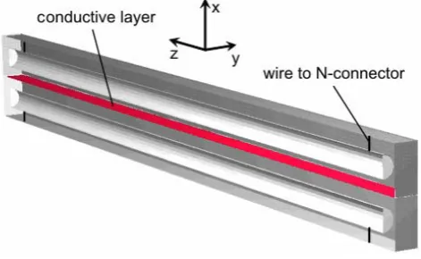
Fig. 2. Skin-effect transmission line coupler.
uation of different possible reflector materials for a new open area test site which is currently under construction.
2 Measurement method and setup
For the measurements a pair of identical transmission line 2-port devices are made from copper and fitted with N-connectors (Fig. 2). Each device contains a coaxial wave-guide, with a circular inner conductor (length l=105 mm, diameterd=3 mm) and an outer conductor having a square cross section (6.5 mm x 6.5 mm, lengthl=110 mm). One side of the outer conductor is entirely left open as a slot, while the housing consists of a large metal area to contact the de-vices. If the slot is closed with a solid metal plate, the device is completed to become a precision 50coaxial line with low insertion loss and a low input reflection coefficient. The
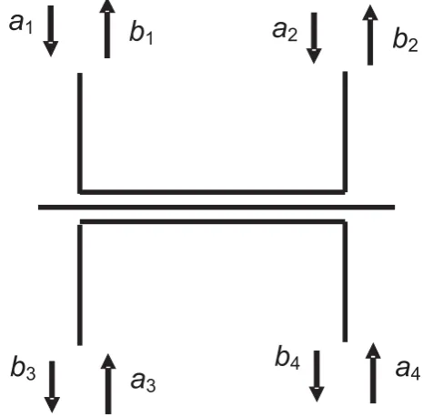
Fig. 3. Four-port representation of an ideal transmission line cou-pler.
measured input and output return loss shows that by the me-chanical design, the coupler devices are well matched up to 3 GHz, ensuring a low voltage standing wave ratio (VSWR) on both coaxial lines. If both devices are attached to oppo-site sides of the separating metal plate, the crosstalk between the two coaxial compartments of the 4-port is strongly re-duced depending on the shielding properties of the material. If the metal plate is removed and the devices are directly con-nected, there is a maximum coupling between the electric and magnetic fields in the two slots. In this configuration the 4-port behaves like a conventional directional coupler – but, of course, here directivity and bandwidth are not optimized for that purpose. Fig. 3 shows the 4-port representation of the transmission line coupler indicating the wavesa1, ..., a4 in the forward direction andb1, ..., b4in the backward direc-tion. In the ideal case it is loss-less and reciprocal. Therefore it can be described by scattering parametersSik=Ski with
b1 b2 b3 b4
=
S11≈0S12≈1 S13 S14 S21≈1S22≈0 S23 S24
S31 S32 S33≈0S34≈1 S41 S42 S43≈1S44≈0
·
a1 a2 a3 a4
.(1)
ing currentI (t )of amplitudeI0and angular frequencyωcauses a current densityJxin the shielding material.
Shielding effectiveness measurements can only be made in comparison to a reference material. The first reason why it is not desirable to use the direct connection as 0 dB-reference for measurements of shielding material is that the devices are no longer 50lines. The second reason follows from the fact that the coupling mechanism is different, if very thin, but highly conductive material is inserted between the two devices. As with the bulk metal plate described above, both sides are then again 50lines. The excitation signal on one side causes a current distribution which is nearly the same as if the coaxial lines were completely separated. In this case the coupling into the second compartment is no longer caused by electromagnetic fields in air, instead it may be best described by the skin effect, which makes a small fraction of the current distribution on the excited input line side “visi-ble” at the other surface of the thin material. This situation is depicted in Fig. 4. The propagation of external fields into a conductive material under these conditions is discussed by Jackson (2002). The current density in the conductive ma-terial decays with the distance from the surface where the excitation takes place. The coaxial line at the output side is excited by a low-impedance, travelling wave current distri-bution on one of its surfaces – a situation which is difficult to model with conventional transmission line theory, because distributed generators would be required.
To test these assumptions, measurements as well as cal-culations based on a numerical simulation model were per-formed for the coupling devices described above, separated by foils of different thickness made from stainless steel. Ma-terials of 10µm, 20µm, 25µm, 30µm and 40µm thickness were available for this purpose.
The two ports of the VNA were connected to one port of each device, with the other port of the transmission lines each terminated with a precision 50load resistor. Two different arrangements were then measured, one with the port con-nectors in close proximity (referred as the forward direction, ports 1 and 3 as in Fig. 3), and the other with one line in
Fig. 5. Computer model of the skin-effect transmission line coupler.
reverse direction (ports 1 and 4 as in Fig. 3), with the VNA ports at opposite ends.
3 Numerical simulation model
For the numerical evaluation of the transmission properties of the empty coupler and the coupler with foil the method of moments implemented in the program Concept II (Singer and Br¨uns, 2006) seemed appropriate. This numerical pro-gram code offers a special feature, which seemed best suited to calculate the transmission through highly reflective and very thin layers. It accurately calculates the penetration of waves through highly reflective materials with high shield-ing attenuation – provided that the material is thin and highly conductive.
Under these circumstances the energy flow inside the ma-terial is perpendicular to the surface, and its propagation is well described by a transmission-line approach, where the attenuation along the line is derived from the skin-effect for-mula.
The problem was to define a geometrical model which was accurate enough to ensure an unidirectional energy flow and a proper smooth current distribution along the excited trans-mission line. Figure 5 shows the simulated geometry. The model consists of two different dielectric bodies ofr=1 with ideally conducting metallic surfaces and embedded conduc-tors which represent the two coupler halves. The connections from the N-connector to the inner conductor are simply mo-delled by 1 mm thick wires of 5 mm length which are con-necting the conductors to the outer surface of the slot wave-guide in which they are embedded. All wires are loaded with a 50impedance. A signal of constant power is fed in port 1. Scattering parameters are derived from the currents ob-served on the wires.
Fig. 6. Comparison between shielding measurements and numerical simulations forS41.
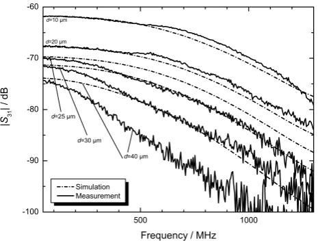
Fig. 7. Comparison between shielding measurements and numerical simulations forS31.
benefits from the symmetry of the devices with regard to the cross section shown in Fig. 5 which reduces the amount of variables and computation time by a factor of two. The si-mulations were performed with approximately 13 500 com-plex variables on a PC with 2 GByte RAM using swap files on the hard disk. A single simulation run involved 60 fre-quency steps of 50 MHz up to 3 GHz and took approximately three days.
4 Comparison of measurements and simulations
We performed measurements with stainless steel foils of known thickness and conductivity to be able to relate ma-terial properties to their measured coupling strength and to
Fig. 8. Measurement setup with increased dynamics.
verify our numerical simulations. The measurement dynam-ics are in the order of 90 dB. Figure 6 shows a comparison of measurements and simulations for the transmission in re-verse direction (S41) whereas Fig. 7 shows the correspond-ing comparison for the forward direction (S31). Before the measurement the VNA was calibrated. The 0 dB-line corres-ponds to a through connection between the VNA ports.
In both cases we see a good agreement between measure-ments and simulations for the lower frequencies, especially for 10µm and 20µm thick foils. As the frequency increases, the discrepancy between simulations and measurements be-comes more pronounced, especially in the case ofS31. We attribute this to the fact that the modelled geometry lacks a sufficient level of detail to represent standing waves in the output section correctly. Furthermore, the measured cou-pling ranges below the simulated results. Obviously losses are not sufficiently accounted for as the coupler housing is assumed to be ideally conducting. Therefore, the reverse (S41) direction should be preferred for the measurement of the shielding effectiveness. For thin foils (10µm and 20µm thickness), the coupling can be calculated with good agree-ment between theory and experiagree-ment up to 3 GHz, whereas for thicker foils accurate calculations are restricted to a few hundred MHz, depending on the thickness. The results show that the measured coupling strength can be reliably related to the thickness of the foil.
5 Applications
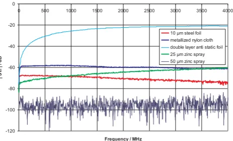
mea-Fig. 9. Attenuation of different panel configurations.
surement dynamics), the connection between panels seems critical. The interface between two adjacent panels is simply established by screwing panels together. This way blank cop-per or zinc surfaces on the panel sides are pressed together.
In order to achieve higher measurement dynamics com-pared to a simple VNA measurement, we use the setup shown in Fig. 8. Precision attenuators of 50 dB followed by a 40 dB amplifier (Amplifier Research 10W1000) are connected to port 1 of the VNA. After calibration of the VNA and a test measurement of the empty coupler two of the attenuators are removed, increasing the measurement dynamics by 30 dB. Next, the couplers were placed orthogonally across the interconnection of two panels (see Fig. 1), forcing the cur-rents to flow across the contact area. Figure 9 shows the re-sults for different measurement positions (at the position of a screw and between two screws) and for different attachment strengths (loose, hand tightened and wrench tightened), both for copper and zinc panels. Only in the case of a loose screw which led to a visible crack between panels, a decoupling of approximately 80 dB was measured. In all other cases the de-coupling was beyond the measurement dynamics of at least 100 dB.
As a second application we compare the shielding effec-tiveness of different surface coating materials. This mea-surement was done to evaluate the performance of possi-ble reflector materials for a new open area test site which is currently under construction at the Physikalisch-Technische Bundesanstalt. Since we were not sure that a thin metal coat-ing is sufficiently reflectcoat-ing we tested its transparency for electromagnetic waves assuming that an intransparent metal layer would reflect most of the incoming radiation. Figure 10 shows the coupling factor S41 for metallized steel cloth, a double layer of anti-static foil, and two different zinc metal layers sprayed on paper using a electro-thermal process com-pared to the previously measured 10µm zinc foil. The 50µm
open area test sites.
zinc layer causes a complete decoupling, already. Although our method does not measure its reflectivity, good reflection properties of such a layer can be assumed as the transmission parameter|S21|is close to 0 dB, representing a low attenua-tion of the signal along the line. A comparable zinc layer will be used for the new open area test site in Braunschweig.
6 Conclusions
We demonstrated a new method to evaluate the shielding ef-fectiveness of planar materials, based on a transmission line coupler. Couplers are broadband devices with well-matched transmission lines at both VNA ports, reducing uncertainty in measured transmission S-parameters. Compared to other methods, it is much easier to handle since it avoids antennas or resonant cavities and allows fast network analyzer mea-surements. Furthermore, with other methods the reflection coefficients at the VNA ports change significantly, when the material sample is inserted. The measurements can be used to specify a reference material to which other shielding ma-terials can be compared.
Measured and calculated transmission coefficients for the transmission line couplers and different metallic shielding materials are in reasonable agreement already (especially at the low-frequency end), which indicates that the numerical model is adequate and suited for the problem discussed here. However, a further refinement of the simulated geometry will help to achieve a better match between measurements and theory. Further work that aims to relate material properties directly to the observed coupling is under way.
Shielding Characteristics of Fabric Made from Metal Clad Aramid Yarn and Wire, EMC 2000 Symp. Rec., 2, 883–886, 2000.
IEEE Std 299: IEEE Standard Method for Measuring the Effective-ness of Electromagnetic Shielding Enclosures, 1997.
Jackson, J. D.: Klassische Elektrodynamik, De Gruyter, Berlin, 2002.