Proportional and Preemption-enabled Traffic
Offloading for IP Flow Mobility: Algorithms and
Performance Evaluation
Yi Ren, Chih-Wei Tung, Jyh-Cheng Chen,
Fellow, IEEE
, and Frank Y. Li,
Senior Member, IEEE
Abstract—IP Flow Mobility (IFOM) enables a user equipment to offload data traffic at the IP flow level. Although the procedure of IFOM-based flow offloading has been specified by 3GPP, how many IP flows should be offloaded and when offloading should be performed are not defined. Consequently, IP flows may be routed to a target access network which has a strong signal strength but with backhaul congestion or insufficient access capability. In this paper, we propose two algorithms, referred to as proportional offloading (PO), and proportional and preemption-enabled offloading (PPO), respectively, for IP flow offloading in hybrid cellular and wireless local area networks. The PO algorithm decides an optimal proportion of IP flows which could be offloaded by considering available resources at the target access network. In the PPO algorithm, both service continuity and network utilization are taken into consideration. Furthermore, a detailed analytical model is developed in order to evaluate the behavior of the proposed algorithms. The analytical model is validated through extensive simulations. The results show that by dynamically adjusting the percentage of traffic flows to be offloaded, PO can reduce blocking probability and increase resource utilization. PPO further improves the performance at the cost of slightly higher offloading overhead.
I. INTRODUCTION
To tackle the ever-growing capacity problem in cellular net-works caused by exponentially growing data traffic nowadays, mobile operators are actively seeking for alternative offloading solutions. Data offloading techniques, which allow re-direct data traffic from a cellular network to another access network (AN), have been widely deployed. For example, operators may offload data traffic from a congested or close-to-congestion evolved universal terrestrial radio access network (E-UTRAN) to an IEEE 802.11 wireless local area network (WLAN), con-sidering the ubiquity of Wi-Fi access points (APs) worldwide. In brief, there are two cases for Wi-Fi offloading. They are: (1) a user equipment (UE) offloads its whole traffic volume to a WLAN AN; and (2) a UE is connected to two access networks simultaneously and only a portion of its traffic is offloaded to
Manuscript received November 16, 2017; revised June 23, 2018. Y. Ren is with the School of Computing Science, University of East Anglia (UEA), Norwich, UK. E-mail: [email protected]
C.-W. Tung is with Mozilla Corp. Taipei, Taiwan, R.O.C. E-mail: [email protected]
J.-C. Chen is with the Department of Computer Science, National Chiao Tung University, Hsinchu, Taiwan, R.O.C. E-mail: [email protected]
F. Y. Li is with the Department of Information and Communication Technology, University of Agder (UiA), N-4898 Grimstad, Norway. E-mail: [email protected] AAA AAA S-GW S-GW
E-UTRAN
UEWLAN AN
Wi-Fi AP Wi-Fi AP S2cEPC
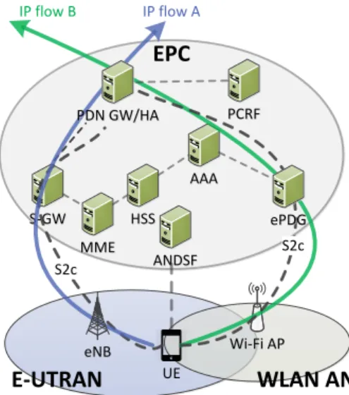
IP flow A IP flow B S2c eNB eNB MME MME HSS HSS ePDGePDG PDN GW/HA PDN GW/HA PCRFPCRF ANDSF ANDSFFig. 1. A simplified IFOM architecture. Traffic from a UE is split into IP flow A and IP flow B, transmitted via E-UTRAN and/or WLAN AN respectively. The right-most dashed line indicates that IP flow B is switched from an eNB in E-UTRAN to a Wi-Fi AP.
the WLAN AN1.Internet protocol (IP) flow mobility (IFOM)
is one of the solutions for the latter case and it is specified by 3GPP [1].
IFOM defines a fine-grained and flexible mechanism by enabling a UE to offload data trafficseamlessly at the IP flow
level. Based on dual stack mobile IPv6 (DSMIPv6), IFOM
allows a UE to selectively re-route parts of its IP flows to another radio access network (RAN), while keeping other ongoing connections or data flows in the current RAN. Fig. 1 illustrates a simplified IFOM architecture. While a dual-mode UE has a connection consisting of several flows (e.g., video stream, delay tolerant traffic, etc.), the UE can keep IP flow A (a real-time flow, for example) staying in E-UTRAN while offloading IP flow B (such as a best effort flow) to a WLAN AN.
However, IFOM does not specify any techniques on when
and how many flows should be re-routed to a WLAN. Nor is
it clear on which criterion or parameter should be adopted to make an offloading decision. Offloading mobile traffic aggressively2 from E-UTRAN to WLAN may degrade user
experience and network performance. For instance, a Wi-1These WLANs in this study are assumed to be managed by the same
operator that controls the E-UTRAN so that the operator is able to monitor the traffic of both access networks and to make decision for load balancing.
2It is meant to perform offloading as long as the signal strength at the target
Fi AP with excellent signal strength may suffer from heavy traffic load or have less effective capacity. On the other hand, passive offloading3 cannot efficiently alleviate congestion in
E-UTRAN and may lead to resource under-utilization at the target AN. Therefore, a more adaptive and effective offloading policy to diminish backaul or target network congestion is needed.
In this paper, we propose two traffic offloading algorithms, referred to as proportional offloading (PO) and proportional and preemption-enabled offloading (PPO), respectively, for hybrid E-UTRAN and Wi-Fi networks. PO adaptively offloads IP flows by considering the available resources at the target network. PPO, instead, allows seamless offloading by preempt-ing certain flows in order to maximize network utilization. Moreover, we specify the time to re-route IP flows in PPO. By doing so, the probability for maintaining IP services becomes higher and the network utilization is increased with moderate signaling overhead. The proposed PO and PPO algorithms distinguish themselves from the existing ones with respect to the following two aspects: 1) while most of the previous studies apply an on-the-spot offloading policy and offload all traffic flows from an AN to another AN, our algorithms offload only a certain percentage of these flows; and 2) offloading failures, which may happen if the available resource at the target AN is insufficient, are often overlooked in other studies but are considered before offloading decision making in our algorithms. Furthermore, our proposed algorithms provide operators with guidelines to offload traffic with an appropriate percentage by jointly considering three network performance parameters.
In brief, the main contributions of this paper are summarized as follows.
• Two algorithms are proposed for IP flow offloading in
hybrid cellular and wireless networks. While PO answers the question onhow manyflows should be re-routed to a target AN, PPO further specifies whenthe flows should be re-routed to the target AN.
• A performance evaluation model to quantitatively analyze the performance of such traffic offloading algorithms is developed. Accordingly, a step-by-step analysis is performed to evaluate and compare the proposed two algorithms.
• Extensive discrete-event simulations are carried out in order to validate the analytical model. The correctness of the analytical model is verified via simulations under various traffic conditions.
The rest of this paper is organized as follows. Section II and Section III provide an overview of related work and the IFOM offloading mechanism, respectively. After the proposed offloading algorithms are presented in Section IV, the analyt-ical model is discussed in Section V. The numeranalyt-ical results are illustrated in Section VI. Section VII concludes this paper. Furthermore, the derivation of the performance expressions is presented in an appendix.
3Offloading is performed only due to insufficient resource at the serving
network, conditioned on high enough signal strength at the target network.
II. RELATEDWORK
Traffic offloading algorithms have been extensively studied recently [2]–[10]. The authors of [2] proposed an integrated offloading algorithm by taking both signal quality and network load into consideration. In [3], an offloading mechanism through the abstraction of software-defined networking (SDN) in the mobile backhaul was proposed in order to provide programmable offloading policies in wireless networks. In [4], the authors proposed a dynamic offloading algorithm via a policy in the access network discovery and selection function (ANDSF). However, the studies presented in [2]–[4] do not take network information into consideration, nor are they pos-sible to offload traffic flows during an ongoing session. These drawbacks may either lead to possible backhaul congestion when accessing an AP, or make it difficult to adjust traffic flows adaptively.
Moreover, several studies [5]–[7] investigated radio ac-cess technology (RAT) selection, enabling to offload traffic by finding an optimally connected network. A survey on mathematical modeling for network selection was presented in [5]. In [6], two game-theory-based approaches were pro-posed for the purpose of load balancing between worldwide interoperability for microwave access (WiMAX) and Wi-Fi. A general and tractable model to analyze inter-RAT offloading was developed in [7]. However, these studies [5]–[7] focused merely on on-the-spot offloading without considering dynamic traffic switching.
Considering the contention-based nature of Wi-Fi access, the authors of [8] proposed a network-assisted user-centric Wi-Fi offloading model to maximize per-user throughput by utilizing available network information in a heterogeneous network. However, the authors of [8] considered only users who can access both Wi-Fi and cellular networks and focused on throughput maximization from users’ perspective. Therein, network utilization and channel occupancy from UEs with Wi-Fi only access were not considered. The work in [9] introduced a hybrid method using both traffic offloading and resource sharing approaches to offload traffic to Wi-Fi APs. The authors in [10] investigated the throughput-power tradeoff in Wi-Fi/cellular network offloading. A utility function is well defined to reconcile the offloading problem as a game. An incentive mechanism is proposed to encourage UEs with enough energy to use cellular networks. In contrast, in this paper we considerdynamic switching of ongoing flows, traffic
load in both access networks, network utilization, as well as
mathematical modeling for traffic offloading in hybrid cellular and Wi-Fi networks.
Recently, delay tolerance offloading for cellular networks with low traffic occupancy has received extensive atten-tion [11]–[15]. The authors in [11] proposed a heuristic approach to delay to-be-offloaded data traffic flows. In [12], the authors proposed to use the potential cellular bytes savings from a delay-tolerant offloading scheduler. These two studies were performed based on the assumption that the offloaded traffic had certain level of delay tolerance. In [13], the authors addressed the research gap and proposed four algorithms to dynamically and adaptively deduce an application’s delay
tol-PDN
PDN UE
PDN connection
...
Default EPS bearer Dedicated EPS bearer Dedicated EPS bearer
Serving GW Serving GW PDN GWPDN GW E-UTRAN E-UTRAN SDF_1 QoS Policy SDF_2 QoS Policy SDF_3 QoS Policy SDF_n QoS Policy
...
Fig. 2. A simplified illustration of a PDN connection with multiple IP flows.
erance. The work in [14] introduced a contract-based incentive mechanism for delayed traffic offloading in cellular networks. The incentive motivates users to leverage their delay and price sensitivity in exchange for service cost. The authors in [15] proposed a queueing analytic model for delayed offloading. A set of performance metrics, such as mean delay, offloading efficiency, were derived. Moreover, the model was validated using a range of realistic scenarios and real data traces. However, these studies [11]–[15] addressed traffic offloading from an application’s point of view. The proposed algorithms therein are not applicable to the scenarios in the studies which require IP-level flow offloading during a session based on IFOM.
III. BACKGROUND OFIFOM
In this section, we introduce the essentials of IFOM.
A. IFOM Architecture
Fig. 1 illustrates a simplified architecture of IFOM for a hybrid E-UTRAN and WLAN AN network4. Generally, the
IFOM architecture can be divided into three parts: evolved packet core (EPC), E-UTRAN, and WLAN AN. In particular, the EPC consists of packet data network (PDN) gateway (GW), serving gateway (S-GW), mobility management entity (MME), policy and charging rules function (PCRF), ANDSF, evolved packet data gateway (ePDG), home subscriber server (HSS), authentication, authorization, and accounting (AAA) server, etc.
The PDN GW is a gateway which provides connectivity between UEs and an external PDN. An interface referred to as “S2c” is defined to support the communication between a PDN GW and a UE [1]. S-GW handles user data functions such as routing and packet forwarding to the PDN GW. MME is responsible for UE mobility, e.g., the procedures for paging and tagging idle mode UE. PCRF is a policy and charging control element supporting policy enforcement, service data flow detection, and flow-based charging. ANDSF provides information for UEs about connectivity to E-UTRAN and WLAN AN. While a UE attempts to access a network, ANDSF will help the UE to decide which network to connect to and provide routing policies to the UE. ePDG is responsible for securing the data transmission between the EPC and UEs for untrusted WLAN access. HSS is a master user database 4In this study, we use E-UTRAN and WLAN AN as examples for 3GPP
access network and non-3GPP access network, respectively.
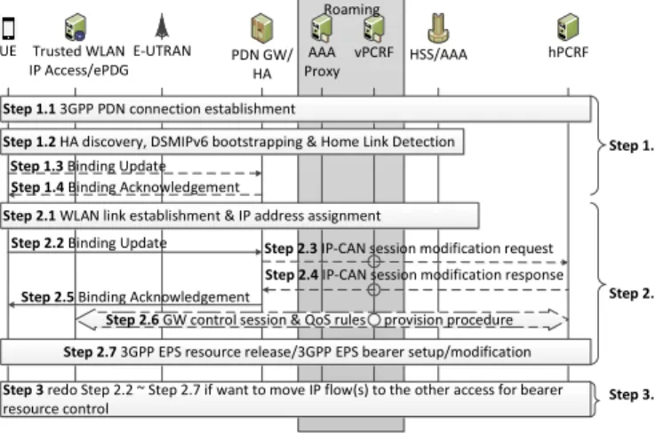
Step 1.1 3GPP PDN connection establishment
Step 1.2 HA discovery, DSMIPv6 bootstrapping & Home Link Detection
Step 2.1 WLAN link establishment & IP address assignment
Step 2.3 IP-CAN session modification requestz
Step 2.7 3GPP EPS resource release/3GPP EPS bearer setup/modification Step 3 redo Step 2.2 ~ Step 2.7 if want to move IP flow(s) to the other access for bearer resource control PDN GW/ HA hPCRF AAA Proxy HSS/AAA E-UTRAN vPCRF Trusted WLAN IP Access/ePDG Roaming
Step 2.2 Binding Update Step 1.3 Binding Update Step 1.4 Binding Acknowledgement
Step 2.5 Binding Acknowledgement
Step 2.4 IP-CAN session modification response Step 1.
Step 2.
Step 3. UE
Step 2.6 GW control session & QoS rules provision procedure
Fig. 3. IFOM offloading procedure for IP flow handover from E-UTRAN to WLAN AN based on 3GPP TS 23.261 [1].
that contains subscriber-related information and manages sub-scriber identities. The AAA server is a server that handles user requests for accessing to network resources and provides authentication, authorization, and accounting services.
B. IFOM Offloading Procedure
IFOM enables a UE to offload data seamlessly at the IP flow level. Considering that multiple flows co-exist from a UE to the EPC, the UE can route IP flows through the available access networks and to selectively offload part of the traffic to a WLAN AN. Fig. 1 illustrates an example that a UE accesses the EPC via two parallel IP flows, where flow A with a higher quality of service (QoS) requirement (e.g., a voice over IP (VoIP) session) goes through the E-UTRAN while flow B with a lower QoS requirement (e.g., a non-real-time (NRT) session) is offloaded to a WLAN AN.
The procedure for IFOM offloading is explained below.
1) PDN connection: When a UE accesses the Internet with
an IP address via the Long-Term Evolution (LTE) network, a PDN connection is established. Within a PDN connection, there exists one or more IP flows which are classified into multiple service data flow (SDF) traffic flows. Fig. 2 shows the relationship between a PDN connection and its IP flows. Within a PDN connection, all evolved packet system (EPS) bearers share the same UE IP address.
2) Binding cache: To offload an IP flow to another wireless
network, the UE needs to obtain a new IP address in the target network. Binding cache is a way regarding how a newly obtained address is associated with the existing IP address. IFOM adopts DSMIPv6 [16] to manage such an IP flow mobility procedure in order to change/update its point of attachment (PoA). Before a UE hands over from an E-UTRAN to a WLAN AN, the ANDSF provides a list of the available access networks to the UE. The UE then attempts to connect to one of the available access networks as the target network. Once a new IP address is assigned to the UE, the UE will register it as a care-of-address (CoA) with its home agent (HA). In this way, a binding is established between the target network and the network with existing flows. To support multiple IP flows, different CoAs may be used.
3) LTE bearer resource control: When a UE accesses a service through the LTE network, the PCRF enables central-ized control to ensure that the service sessions are provided with sufficient radio resources and appropriate QoS. When the available resource is not sufficient to satisfy the service requested, the PCRF may reject the request. When the traffic load in the cellular network becomes heavier, a UE may prefer to offload its traffic to a WLAN AN. At the same time, the cellular network operators may not be willing to offload too many flows due to the consideration of achieving higher network utilization or to get more revenue from end users. So a routing policy has to be designed in order to decide when and how to offload an IP flow.
A step-by-step procedure for IFOM IP flow offloading, including PDN connection, binding cache, and bearer resource control, is illustrated in Fig. 3 Steps 1∼3. For more details, please refer to [1].
C. Routing Policies in ANDSF
A routing policy is an operator’s choice and it is a network-based decision by the ANDSF. A UE will then follow the rout-ing policy decided by its operator to select a RAN and route its traffic flows correspondingly. Although an offloading and routing policy framework has been provided by 3GPP [17], it does not suggest any offloading policies.
To design a routing policy, the ANDSF needs to collect RAN assistance information [18], including cellular access thresholds, WLAN access thresholds, offload preference indi-cation values, backhaul data rate for both uplink and downlink, channel utilization in IEEE 802.11 [19], etc. Before deciding to change the PoA for a specific IP flow, the ANDSF needs also to check whether the flow is re-routable (RR) or not5. A flow may be non-re-routable (NRR) if the UE is only covered by one RAN or it does not have multiple radio interfaces for connections with different RANs.
IV. THEPROPOSEDPOANDPPO ALGORITHMS
In this section, we first present our design goals and then propose two flexible and fine-grained offloading algorithms based on IFOM, referred to as PO and PPO, respectively. While PO focuses on offloading an appropriate percentage,
θ where 0 ≤ θ ≤ 1, of traffic flows to reduce blocking probability and increase network utilization, PPO allows dy-namic switching of the PoA for ongoing flows in order to further improve network utilization of the whole network. The network resources considered in this study are radio resources at the backhaul of a RAT and a WLAN AN, respectively. Note that in the considered scenarios for offloading, a traffic flow is typically offloaded from the E-UTRAN to a WLAN, but a flow may be re-directed back to the E-UTRAN when necessary. Moreover, both PO and PPO are executed at the routing policy server, i.e., the ANDSF shown in Fig. 4. To make offloading decisions which reflect precisely the dynamic feature of traffic variations over time, the ANDSF collects the 5Since both access networks are managed by the same operator, it is feasible
to check the connectivity as well as coverage information for each UE.
statistic information on traffic load and resource utilization from the serving PDN GW, eNB, and WLAN AP periodically and makes proper decisions accordingly.
A. Design Goals
Three performance metrics are defined in this study as presented below. Since the value of θhas impact on all these three parameters, we include it in the notations.
• Access blocking probability, Pb(θ):This is the proba-bility that a request of an IP flow cannot get access to the network, either in the E-UTRAN or in the WLAN. The IP flow considered can be either an RR or an NRR flow. While an NRR flow may be rejected due to lack of resources at the serving RAN, an RR flow may be rejected during the registration phase if there are not enough resources at the target RAN.
• Network utilization, U(θ): The resource utilization of a RAN is a dimensionless parameter represented by the ratio between the number of resource units occupied by ongoing flows and the total number of resource units in the network.
• Offloading overhead, α(θ): This is the additional sig-naling overhead caused by an offloading algorithm. It is calculated as the ratio between the number of offloading requests and the total number of arrivals to a network. Bearing the above definitions in mind, we reiterate the design goal for an offloading algorithm as to increase U(θ) while keepingPb(θ)andα(θ)as low as possible.
B. Proportional Offloading (PO)
As mentioned earlier, an aggressive offloading algorithm offloads UE traffic as long as the signal strength in the target AN is high enough for channel access, whereas a passive offloading algorithm offloads UE traffic only when no resource is available at the serving AN and at the same time the signal strength in the target AN exceeds a pre-defined threshold. However, no traffic condition is considered in these algorithms. In contrast, our algorithms make an offloading decision not only depending on signal strength but also by taking traffic load and available resources at both E-UTRAN and WLAN into consideration.
A basic rule for PO is that a certain percentage of the arrival IP flows should be offloaded to the WLAN while keeping the rest in the E-UTRAN in order to achieve a low blocking probability and high network utilization. When a new IP flow arrives to the E-UTRAN, the routing policy informs the UE whether this flow should be offloaded to the WLAN or not, depending on the rule. The offloading decision on the percentage of IP flows to be offloaded is determined by the ANDSF server. To reduce signaling cost, the information of traffic load and resource utilization is collected periodically by the ANDSF server rather than the UEs. Such information can be collected from the serving PDN GW, eNodeB, or WLAN AP. Based on the collected information, the ANDSF server decides the percentage of traffic offloading and informs each UE on how to route or re-route its traffic flows according to the decided routing policy.
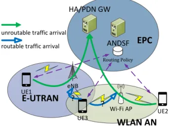
E-UTRAN
WLAN AN
UE1Wi-Fi AP eNB
unroutable traffic arrival routable traffic arrival
UE2 UE3
ANDSF
Routing Policy?
?
HA/PDN GW
EPC
Fig. 4. An illustration of hybrid E-UTRAN and WLAN.
Consider a hybrid network composed of E-UTRAN, WLAN AN, and an overlapped area of both networks, as shown in Fig. 4. A UE may access the EPC through E-UTRAN or/and Wi-Fi RATs. For traffic offloading, a UE follows the routing policy it receives from the ANDSF server. Inside this hybrid RAN, the IP flows to and from UEs are classified into RR and NRR IP flows. As shown in the figure, the flows connecting UE1 and UE2 are non-re-routable since they are covered only by one RAN, whereas the flows from UE3 are re-routable since UE3 is connected to both RANs. If an arriving flow is NRR, the routing policy can only direct it to its serving RAN6. If the arriving IP flow is re-routable, the routing policy will inform the UE whether this flow should stay in the E-UTRAN or should be offloaded to the WLAN AN. Hence, the offloading decision is applicable to arriving IP flows carried by a UE with access opportunities to both the E-UTRAN and the WLAN AN.
In Algorithm 1, we illustrate the procedure of the proposed PO algorithm. Three performance parameters, i.e., network utilization, U(θ), access blacking probability, Pb, and of-floading overhead, α(θ), are considered in our study. Their expressions will be presented in Sec V. In order to make a proper and balanced decision based on these three performance parameters, we have introduced three weight factors, w1,w2, andw3 which could be configured according to an operator’s preference. However, to make our algorithms more flexible, we do not suggest any concrete values for these weight factors due to the consideration that such a value should be determined by a mobile operator when making their offloading policies.
Discussion: PO provides guidelines to identify an
appro-priate percentage of traffic load for offloading, but it allows offloading merely at the beginning of flow access. When an NRR flow arrives, an ongoing flow would probably be forcibly terminated if no resources are available at the serving AN. As commonly understood from a QoS point of view, to forcibly terminate an ongoing flow is more annoying for an end user 6A serving RAN is the radio access network a UE is currently connected
to, whereas a target RAN is the radio access network to which an IP flow attempts to join via offloading.
Algorithm 1Selecting the percentage of re-routable IP flows to be offloaded in PO.
Input: λe, λw: Mean value of NRR IP flow arrival rate from E-UTRAN and WLAN AN, respectively
Input:λm: Mean value of re-routable IP flow arrival rate from E-UTRAN and WLAN AN overlapped area
Input:Ce,Cw: Resource capability of E-UTRAN and that of WLAN AN.
Input:µe,µw: Mean value of UE residence time in E-UTRAN cell and WLAN cell, respectively
Input:T: Evaluation interval
Output: θ: The percentage of re-routable IP flows to be of-floaded
Ensure: The signal strength in the target RAN is enough to access
1: sett:=T
2: whilet≥1do
3: CalculateU(θ)using (3) CalculatePb(θ)using (1) Calculateα(θ)using (7)
arg maxθ{w1U(θ)+w2Pb(θ)+w3α(θ)}, wherew1,w2, and
w3 are weight factors.
Offloadθ percent IP flows to WLAN AN
sett:=t−1
4: end while
than being rejected before the session is established. It could also further improve network utilization if we could dynami-cally offload traffic on-the-fly. These observations motivate us to develop another offloading algorithm which allows UEs to switch the PoA of an ongoingflow.
C. Proportional and Preemption-enabled Offloading (PPO) As traffic load increases, more IP flows may be offloaded to WLAN. Considering that if there are additional incoming traf-fic flows, either RR or NRR, to the WLAN AN, the blocking probability could be high. The PO algorithm presented above performs traffic offloading to reduce blocking probability and increase network utilization merely for E-UTRAN. In contrast, PPO may re-route IP flows from a WLAN to an E-UTRAN in order to increase resource utilizationof the whole network. It also specifies the time7for a UE to perform PoA switching
based on IFOM. The proposed PPO is designed to dislodge the negative effect of offloaded traffic on NRR IP flows in the WLAN AN. When an NRR IP flow arrives to the WLAN AN and all available resources are occupied, the ANDSF will not block the request. Instead, it chooses an ongoing re-routable IP flow and re-directs it to the E-UTRAN so that both flows can be kept in the hybrid network. In a nutshell, the PPO scheme allows dynamic switching of the PoA for ongoing flows so that the network utilization for the whole network including both E-UTRAN and WLAN is improved.
Fig. 5 shows the procedure of the proposed PPO. After the PCRF receives the request to add an NRR IP flow to the WLAN AN which does not have enough available resource (Step 2.3), it checks whether there are re-routable IP flows in the WLAN AN or not. If there is one re-routable IP flow, the PCRF selects it as a victim flow and sends a request to the PDN GW for PoA switching to E-UTRAN (Step 2.5). If there 7The time instant of thesession modification requestis initiated, which is
Step 1 UE1 is connected simultaneously to 3GPP and WLAN accesses and multiple bindings and multiple IP flows are registered at the HA.
Step 2.1 UE2 establish a PDN connection establishment over WLAN.
Step 2.7 UE1 switches the movable IP flow to E-UTRAN and release the resource
Step 2.4 PCRF checks the QoS, make a decision, and choses a victim movable IP flow to switch to E-UTRAN PDN GW/ HA hPCRF AAA Proxy HSS/AAA E-UTRAN vPCRF Trusted WLAN IP Access/ePDG Roaming
Step 2.2 Binding Update
Step 2.9 Binding Acknowledgement UE1 UE2
Step 2.3 IP-CAN session modification requestz
Step 2.8 IP-CAN session modification response
Step 2.5 request to PDN GW to indicate UE1
Step 2.6 request to UE1 for switching its flow
Fig. 5. A message flowchart for PPO offloading: IP flows may be dynamically re-directed back to E-UTRAN based on 3GPP TS 23.261 [1].
are multiple re-routable flows, one of them will be selected randomly as the victim flow. The PDN GW requests to the UE via the S2cinterface (Step 2.6). If the PoA switching is successful, the released resource in the WLAN AN will be re-allocated to accommodate the arriving NRR IP flow. By adding slight signaling overhead, only an additional decision and two request flows (shown in Step 2.4 ∼Step 2.6), to the current IFOM message flowchart, the proposed PPO algorithm can offload traffic flows dynamically. In this way, the network utilization is improved while the access privilege of NRR IP flows is still guaranteed.
Discussion: The procedure for PoA switching may lead to
extra delay. To ensure seamless service continuity based on
PPO,we apply PoA switching to NRR flows only. Furthermore,
additional signal overhead may be imposed which is the cost for higher network utilization and lower blocking probability. In the next section, we propose an analytical model to analyze the performance of such traffic offloading algorithms.
V. PERFORMANCEANALYSIS
In this section, we develop a framework to analyze the performance of traffic offloading algorithms for IFOM. Fol-lowing a common practice used in communication network modeling [20]–[22], the arrivals of IP flows to both E-UTRAN and WLAN are assumed to be Poisson processes. We denote
λm,λe, and λw as the arrival rate for RR IP flow, NRR IP flows to the E-UTRAN, and NRR IP flows to the WLAN, respectively. Let θ be the percentage of re-routable IP flows to be offloaded. The arrival rate for re-routable IP flow registrations to the WLAN and the E-UTRAN becomes θλm and (1 −θ)λm, respectively. The notations adopted in our analysis are listed in Table I. In the followings, we conduct performance analysis for both PO and PPO.
A. Blocking ProbabilityPb(θ)
For PO, forced termination of an ongoing IP flow will not occur since it offloads IP flows only at the beginning of access. Let pP O
bw andp P O
be represent the probabilities that the WLAN
TABLE I LIST OFNOTATIONS
Notation Explanation
U(θ) The resource utilization
α(θ) The additional signaling overhead caused by an offloading algorithm
λw/λe Mean value of the NRR IP flow arrival rate to WLAN AN/E-UTRAN respectively
λm Mean value of the RR IP flow arrival rate to the E-UTRAN and WLAN AN overlapped area λtr Mean value of the arrival rate for transferring
IP flows
λef f The effective arrival rate seen by the system
tf IP flow lifetime
ter/te,i/twr/tw,i IP flow residence time in the E-UTRAN/i-th E-UTRAN cell/WLAN AN/i-th WLAN AN cell τe,i/τw,i The residual life ofte,i/tw,i
τf e,i/τf w,i The residual life of an IP flow after UE visited the i-th E-UTRAN/WLAN AN cell
τe,i∗ The age ofte,i
1/µ Mean value of IP flow lifetimetf
1/µe(1/µw) Mean value of the IP flow lifetime in the E-UTRAN (WLAN) cell
1/ηw(1/ηe) Mean value of the resident time in the i-th WLAN cell tw,i(E-UTRAN cellte,i)
Cw/Ce WLAN AN / E-UTRAN resource capacity
ρP O
e /ρP P Oe E-UTRAN cell resource utilization for PO/PPO respectively
ρP Ow /ρP P Ow WLAN AN cell resource utilization for PO/PPO respectively
PbP O/PbP P O The probability that an IP flow request cannot get access to the network for PO/PPO respec-tively
pP Obe /p P P O
be The probability of IP flows being blocked in the E-UTRAN cell for PO/PPO respectively pP Obw/p
P P O
bw The probability of IP flows being blocked in the WLAN AN cell for the PO algorithm and the PPO algorithm respectively
pP P O
bh The probability of high priority IP flows being blocked in the WLAN AN cell for the PPO algorithm
pP P Of The probability of failure when transferring re-routable IP flows from the WLAN AN to the E-UTRAN cell
Le/Lw The number of IP flows accessing through the E-UTRAN/WLAN AN
ρe/ρw The resource utilization in the E-UTRAN/WLAN AN
ρP Oe /ρP Ow The effective network utilization for the E-UTRAN/WLAN AN
AN and the E-UTRAN block the request of an arriving IP flow, respectively.
According to PO, there are four reasons that an IP flow cannot access the network. They are: (1) an arriving NRR flow to the WLAN AN is blocked; (2) an arriving NRR flow to the E-UTRAN is blocked; (3) an arriving RR flow which should be kept to the E-UTRAN (i.e., not offloaded) is blocked; and (4)
an arriving RR flow which should be offloaded to the WLAN is blocked. Therefore, the blocking probability of PO for a given offloading percentage θ,PP O
b (θ), is obtained as: PbP O(θ) =p P O bwλw+pP Obe λe+pP Obe (1−θ)λm+pP ObwpP Obe θλm λw+λm+λe . (1) For PPO, there is another reason that a flow would be blocked in addition to the same four reasons mentioned above for PO. That is, an ongoing RR flow which is expected to switch its PoA from the WLAN to the E-UTRAN is blocked, with a probability of pP P O
f . LetpP P Obe ,pP P Obh , and PbwP P O be the probabilities that the E-UTRAN blocks an arriving flow request, the probabilities that the WLAN AN blocks a request from a higher priority (i.e., NRR) and a lower priority (i.e., RR) IP flow, respectively. The blocking probability for PPO,
PbP P O(θ), is derived as: PbP P O(θ) = pP P Obh λw+ (pP P Of +p P P O bw p P P O be )θλm λw+λm+λe +p P P O be λe+pP P Obe (1−θ)λm λw+λm+λe . (2)
B. RAN Resource Utilization U(θ)
LetLeandLwbe the number of IP flows accessing through the E-UTRAN and the WLAN AN, respectively. We assume that each flow occupies the same amount of resource, as one resource unit, and consider the amount of resource units at the WLAN AN and the E-UTRAN as Cw andCe units. The resource utilization of the hybrid RAN consisting of an E-UTRAN and a WLAN AN,U(θ), then can be easily computed as follows:
U(θ) = Le+Lw
Ce+Cw
. (3)
Denote by ρe and ρw the resource utilization in the E-UTRAN and the WLAN AN, respectively. Since no queue is considered in our performance evaluation model, the number of resource units occupied in each RAN is equal to the product of its resource utilization and the total resource units in that network. Therefore, we can rewrite (3) as:
U(θ) =Ceρe+Cwρw
Ce+Cw
. (4)
Accordingly, the RAN resource utilization for PO is ex-pressed as: UP O(θ) = ρ P O e (θ)Ce+ρP Ow (θ)Cw Ce+Cw , (5)
and for PPO, it becomes:
UP P O(θ) =ρ
P P O
e (θ)Ce+ρP P Ow (θ)Cw
Ce+Cw
, (6)
where ρP Oe (or ρP P Oe ) and ρP Ow (or ρP P Ow ) represent the resource utilization in the E-UTRAN and the WLAN AN for PO or PPO, respectively.
TABLE II
SIMULATIONPARAMETERCONFIGURATION
Parameter Value
1/µ 600 sec
ηe 2µ
1/ηw for WLAN 300 sec
Cwfor WLAN 5 units
λ(light) 0.2Cµ
λ(heavy) 2Cµ
η 0.1µ∼10µ
ηw 2µ
1/ηe for E-UTRAN 300 sec
Cefor E-UTRAN 10 units
λ(medium) Cµ
C. Offloading Overheadα(θ)
The offloading overhead depends heavily on the number of offloading requests between the E-UTRAN and the WLAN. Whenθincreases, there are more IP flows attempting to access the WLAN AN, leading to a higher blocking probability in the WLAN AN. If a request for adding an IP flow is blocked by the WLAN AN, the UE with an arriving flow will send another request to the E-UTRAN for possible access. We regard these requests as offloading overhead. Thus, the offloading overhead for PO, αP O(θ), is calculated as:
αP O(θ) =p
P O
bw(1−θ)λm
λw+λm
. (7)
In PPO, when an event to transfer an ongoing re-routable flow to the E-UTRAN happens, it also causes signaling over-head. Therefore, the offloading overhead in PPO,αP P O(θ), is derived as: αP P O(θ) =p P P O bw (1−θ)λm+ (pP P Obw −p P P O bh )λw λw+λm . (8) In the appendix, we will further derive the detailed expres-sions for the above three parameters.
VI. SIMULATIONS ANDNUMERICALRESULTS
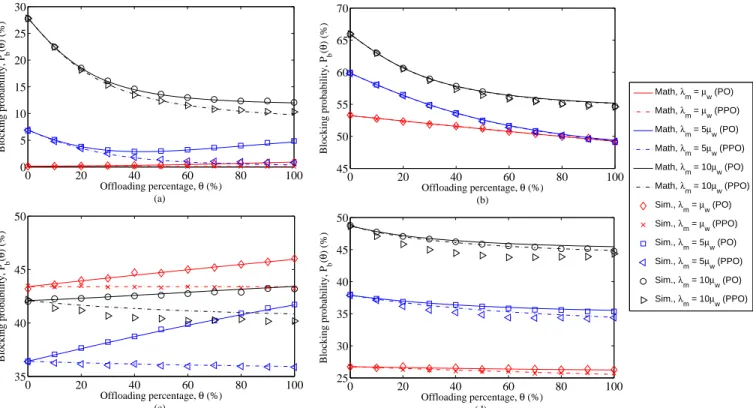
The proposed PO and PPO algorithms are implemented in ns-2 [23], version 2.35, based on the network scenario shown in Fig. 4. The parameters are configured as illustrated in Tab. II unless otherwise stated. The results reported in this section are the average values obtained over 1,000,000 simulation time. The confidence intervals are so small that they overlap with the lines (the results by analysis) and the points (the results by simulations). The solid and dash-dot lines shown in the figures refer to the results obtained from PO and PPO, respectively.
In the following subsections, we illustrate the performance of PO and PPO with respect to blocking probability, resource utilization and offloading overhead as a function of traffic intensity and offloading percentage. Note thatθ= 100 %and
θ= 0 %in each figure correspond to aggressive and passive offloading policies which lead to un-adjustable performance.
Using PO and PPO, we can adjust the value of θ properly in order to achieve satisfactory performance.
The sub-figures in Figs. 6, 7, and 8 show the results obtained under four different traffic intensity levels:
• Sub-figure (a): Light traffic in both E-UTRAN and
WLAN (with Cµλ = 0.2).
• Sub-figure (b): Heavy traffic in E-UTRAN (with Cµλ = 2) and light traffic in WLAN. More IP flows can be accom-modated in the WLAN AN.
• Sub-figure (c): Light traffic in E-UTRAN (with Cµλ = 2)
and heavy traffic in WLAN.
• Sub-figure (d): Medium traffic in both E-UTRAN and
WLAN (with Cµλ = 1). In this case, both cells can accommodate their NRR IP flows, but the offloaded RR IP flows may cause cell congestion.
A. Effects ofθ and λm onPbP O(θ)and P
P P O b (θ)
Fig. 6 plotsPbP O(θ)andPbP P O(θ)againstθ(the percentage of offloading traffic) and λm (the arrival rate for re-routable flows). When the intensity of NRR traffic in both the E-UTRAN and the WLAN AN is low ( λe
Ceµe = 0.2<1,
λw
Cwµw =
0.2 < 1), UEs can access the network with a low blocking probability. With a higher arrival rate of RR traffic (λm), however, the blocking probability increases. Offloading will then help to reduce blocking probability. For example, when
λm = 10µw, PbP O(θ) decreases as θ increases. This is because a certain amount of arriving flows are offloaded. When
λm = µw, there are few re-routable IP flows in the WLAN AN. When more IP flows attempt to access the WLAN AN (due to a higher θ), some NRR IP flows may be blocked, leading to a slightly increased blocking probability.
Whenλm= 5µw,PbP O(θ)does not behave monotonically, reaching a minimum value whenθ≈40%. The reason is that offloading re-routable IP flows reduces the access opportunity for the NRR IP flows in the WLAN AN but increases the access probability of re-routable traffic. As the result of a decreased PP O
b for re-routable traffic and an increasedPbP O for NRR traffic, an optimal value forθis reached. On the other hand, PPO is able to protect the NRR IP flows in the WLAN AN by re-directing certain amount of RR flows back to the E-UTRAN, leading to a monotonically decrease of PbP P O in this case.
Fig. 6(b) shows the result when the traffic intensity in the E-UTRAN is high and the WLAN AN is low ( λe
Ceµe = 2>
1, λw
Cwµw = 0.2<1). No matter how many RR IP flows arrive,
offloading IP flows always reduces the blocking probability with both PO and PPO. The larger theθ, the lower thePbP O(θ) and thePbP P O(θ). Since no significant benefit is achieved by PPO in this case, employing PO is recommended considering its lower offloading overhead (to be presented later).
With light traffic intensity in the E-UTRAN and heavy traf-fic in WLAN (configured as λe
Ceµe = 0.2<1,
λw
Cwµw = 2>1),
the PbP O(θ) grows linearly when θ increases as shown in Fig. 6(c). On the other hand, PPO transfers certain amount of IP flows back to the lightly-loaded E-UTRAN, resulting in both a higher access opportunity in the E-UTRAN and a
lower blocking probability in the WLAN AN. Hence, the total blocking probability is decreased with a higherθ.
Furthermore, it is interesting to observe that when λm =
5µw, lowerPbP O(θ)andPbP P O(θ)are achieved in comparison with under the traffic conditions of bothλm=µw andλm=
10µw. This is because the available resource in WLAN is very low (Cw = 5versus Ce= 10) and the WLAN AN could be easily congested when more NRR flows arrive. With more arriving RR flows (λm = 5µw), many of them could be re-allocated to the E-UTRAN, leading to a lowPb for both PO and PPO. When the number of RR flows further increases, however, no enough resources are available in the E-UTRAN either. The Pb then increases again.
Fig. 6(d) illustrates that the blocking probability decreases slightly when more flows are offloaded for both PO and PPO with medium traffic load in both the E-UTRAN and the WLAN AN. This means that when both networks are busy, offloading traffic does not reduce blocking probability to a large extent.
In summary, PPO reduces blocking probability more signif-icantly than PO does under most traffic conditions. For a given traffic condition, an appropriateθvalue needs to be configured.
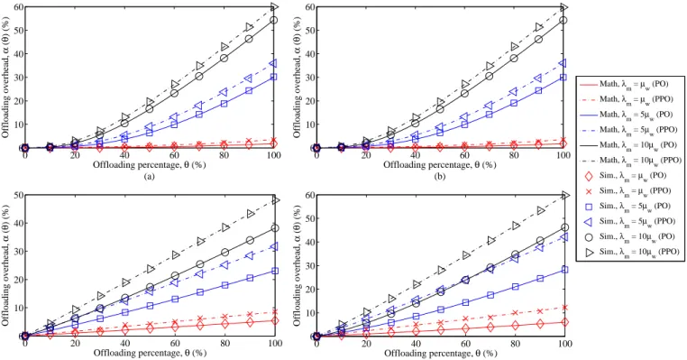
B. Effects ofθand λonUP O
b (θ)andUbP P O(θ)
Fig. 7 shows how the RAN resource utilization, UbP O(θ) and UbP P O(θ), varies when θ and λm change. In three out of the four traffic conditions, the utilization increases whenθ
increases for both PO and PPO as shown in Figs. 7(a), (b), and (d). In these three cases, the traffic intensity in the WLAN AN is light or medium. Thus, offloading more flows to WLAN would lead to higher resource utilization. The larger theθ, the higher theUP O(θ)and the UP P O(θ).
However, when the WLAN AN is already heavily loaded, increasing θ will result in lower resource utilization if PO is employed. The reason is that offloading IP flows towards an already heavily loaded target network will make it quickly congested. On the other hand, when PPO is employed, some of those would-be-rejected flows by the WLAN AN are trans-ferred back to the E-UTRAN. Thus, the resource utilization keeps at a quite stable level under PPO.
In short, from the perspective of maximizing RAN resource utilization, offloading more IP flows to the WLAN AN would be beneficial as long as the target network is not close to congestion. PPO keeps the utilization stable even when the WLAN AN is busy. When the traffic load in the WLAN AN is low or medium, more flows should be offloaded when more re-routable flows arrive in order to achieve higher resource utilization. When few re-routable flows arrive, however, little benefit could be achieved by traffic offloading.
C. Effects of θand λonαP O(θ)and αP P O(θ)
Finally, we look at the offloading overhead αP O(θ) and
αP P O(θ) in Fig. 8 against θ and λm. As expected, higher overhead is introduced with both PO and PPO when more flows are offloaded. This is because that a higher number of registrations are needed when more flows are offloaded. With PPO, this number will further increase due to the fact that
0 20 40 60 80 100 0 5 10 15 20 25 30 Offloading percentage, θ (%) (a) Blocking probability, P b ( θ ) (%) Math, λm = μw (PO) Math, λm = μw (PPO) Math, λm = 5μw (PO) Math, λm = 5μw (PPO) Math, λm = 10μw (PO) Math, λm = 10μw (PPO) Sim., λm = μw (PO) Sim., λm = μw (PPO) Sim., λm = 5μw (PO) Sim., λ m = 5μw (PPO) Sim., λm = 10μw (PO) Sim., λm = 10μw (PPO) 0 20 40 60 80 100 45 50 55 60 65 70 Offloading percentage, θ (%) (b) Blocking probability, P b ( θ ) (%) 0 20 40 60 80 100 35 40 45 50 Offloading percentage, θ (%) (c) Blocking probability, P b ( θ ) (%) 0 20 40 60 80 100 25 30 35 40 45 50 Offloading percentage, θ (%) (d) Blocking probability, P b ( θ ) (%)
Fig. 6. Blocking probabilityPP O
b (θ)andPbP P O(θ)with different re-routable flow arrival rateλmand offloading percentageθ.
a portion of the flows are re-routed back to the E-UTRAN. As a consequence, the offloading overhead caused by PPO is always higher than that of PO.
Recall that lower blocking probability and higher resource utilization can be achieved by PPO as presented earlier in this section. It is therefore of interest to investigate further the tradeoff between the benefits and the cost when employing PPO. For example, when the arrival rate of re-routable IP flows is high (λm = 10µw), offloading 50% of arriving IP flows will lead to high U(θ)(80% or higher) and moderate Pb(θ) at a cost of around20%of α(θ). When the arrival rate of re-routable IP flows is low (λm=µw), offloading or not does not have significant impact on Pb(θ)andU(θ). Thus, offloading passively (i.e., θ= 0%) is recommended considering its zero offloading overhead. When a medium level of re-routable flows arrive, e.g., when λm= 5µw, an appropriateθ value needs to be configured based on the system requirement. If a mobile operator can tolerate high offloading overhead, allocating all of the IP flows to the WLAN AN can maximize the RAN resource utilization. On the other hand, if the mobile operator intends to minimize blocking probability, offloading a lower percentage, e.g.,30%, of IP flows to the WLAN AN is a better policy with low offloading overhead.
To summarize, PO defines a simple yet effective offloading policy which can reduce blocking probability for network access and raise RAN resource utilization. PPO further reduces
PbP P O(θ)and increasesUP P O(θ)even when the WLAN AN is busy, at a cost of a slightly higher level of offloading overhead. Since PPO performs properly under different traffic conditions, it is a more efficient and favorable option for traffic offloading in hybrid cellular networks. With a higher
percentage for traffic offloading, the blocking probability goes monotonically downwards and the resource utilization becomes gradually higher or keeps stable while the signaling overhead grows monotonically.Therefore, to design a suitable offloading policy, a mobile operator needs to identify an
appropriateθthat leads to an optimal level ofPb(θ)andU(θ)
at a tolerable level of α(θ).
VII. CONCLUSIONS ANDFUTUREWORK
In this paper, we investigate the IFOM mechanism that enables a UE with multiple IP flows to switch a specific IP flow between E-UTRAN and WLAN. When a UE accesses a new IP service or switches its IP flows to another RAN, it needs to send a Binding Update to the serving PDN GW and requests for IP bearer establishment. If the resource is not enough, the request would be blocked. More specifically, we propose PO to reduce blocking probability and improve RAN resource utilization. However, PO may limit the access opportunities for WLAN-only UEs due to the offloaded traffic flows. Therefore, we further propose PPO as an advanced algorithm to re-direct re-routable IP flows back to the E-UTRAN in order to improve the access opportunities of those WLAN-only UEs and increase resource utilization for the whole network.
As a candidate solution for network based IFOM (NBI-FOM) [24], we propose an IP flow offloading procedure by adding a step with a decision and two requests via the S2c interface. Furthermore, we have developed an analytical model and performed extensive simulations to validate the mathematical model and evaluate the performance of the proposed PO and PPO algorithms with respect to blocking
0 20 40 60 80 100 20 30 40 50 60 70 80 Offloading percentage, θ (%) (a) CN utilization, U( θ ) (%) 0 20 40 60 80 100 65 70 75 80 85 90 95 Offloading percentage, θ (%) (b) CN utilization, U( θ ) (%) 0 20 40 60 80 100 40 50 60 70 80 90 Offloading percentage, θ (%) (c) CN utilization, U( θ ) (%) 0 20 40 60 80 100 75 80 85 90 95 Offloading percentage, θ (%) (d) CN utilization, U( θ ) (%) Math, λ m = μw (PO) Math, λ m = μw (PPO) Math, λm = 5μw (PO) Math, λm = 5μw (PPO) Math, λ m = 10μw (PO) Math, λm = 10μw (PPO) Sim., λm = μw (PO) Sim., λ m = μw (PPO) Sim., λm = 5μw (PO) Sim., λm = 5μw (PPO) Sim., λ m = 10μw (PO) Sim., λm = 10μw (PPO)
Fig. 7. Network utilizationUP O
b (θ)andUbP P O(θ)with different re-routable flow arrival rateλmand offloading percentageθ.
probability Pb(θ), RAN resource utilization U(θ), and of-floading overhead α(θ). Our study indicates that the θ value should not be kept as a constant in an offloading policy. By dynamically adjustingθto an appropriate value, PO can reduce blocking probability and increase resource utilization. PPO further improves the performance with an acceptable cost of signaling overhead.
For future work, we plan to explore the impact of medium access control protocols on the performance of both PO and PPO, especially in terms of latency. Besides, it is interesting to study the impact of PO and PPO on core networks.
APPENDIX: DERIVATION OFPERFORMANCEPARAMETER
EXPRESSIONS
In this appendix, we further derive the expressions for the three parameters defined in Section V. To do so, we need to calculate the arrival rates and service rates first.
A. Arrival Rates and Service Rates
Consider the behavior of a UE in the overlapped area of a hybrid E-UTRAN and WLAN AN. Let the IP flow lifetime be
tf, and the residence time in the E-UTRAN and the WLAN AN beter andtwr, respectively. Assume thattf,ter, andtwr are exponentially distributed with a mean value of1/µ,1/ηe, and1/ηw, respectively.
Fig. 9 illustrates an event (such as arrival, handover, de-parture, etc.) diagram for an IP flow from a mobile UE. The arrivals to the E-UTRAN can be generally classified into three cases. That is, (1) initial access (occurred at t1); (2) handover
access (occurred att5,t8,t9); and (3) re-directed access since a WLAN AN is fully occupied and the flow is switched back to the E-UTRAN (occurred att4,t7). At the period between
t2 andt4 (also betweent6andt7), the UE is attached to both the E-UTRAN and the WLAN AN. Thus, during this period it is regarded as a re-routable IP flow. In the rest of the time, the PDN GW considers this IP flow as an NRR traffic flow. The other times shown in Fig. 9 are as follows.te,i: the residence time in thei-th E-UTRAN cell;tw,i: the residence time in the
i-th WLAN AN cell; τe,i (or τw,i): the residual duration of
te,i (ortw,i); andτe,i∗ : the age of te,i.
To find the service rate, we consider the initial and handover cases. Denote the remaining IP flow lifetime asτf e,i after the UE visited the i-th E-UTRAN cell. Based on the memory-less property of the exponential distribution, the probability density function (pdf) of the residence time in any E-UTRAN cellfe(t)becomes: fe(t) = Z ∞ τse,i=t fs(τse,i)fer(t)dτse,i + Z ∞ ter=t fer(ter)fs(t)dter= (µ+ηe)e−(µ+ηe), (9) with a mean value
1 µe =E[te] = Z ∞ t=0 tfe(t)dt = Z ∞ t=0 t(µ+ηe)e−(µ+ηe)dt= 1/(µ+ηe). (10) Similarly, the residual time of an IP flow in the WLAN AN isτf w,i and its residence time in the WLAN AN istwr.
0 20 40 60 80 100 0 10 20 30 40 50 60 Offloading percentage, θ (%) (a) Offloading overhead, α ( θ ) (%) 0 20 40 60 80 100 0 10 20 30 40 50 60 Offloading percentage, θ (%) (b) Offloading overhead, α ( θ ) (%) 0 20 40 60 80 100 0 10 20 30 40 50 Offloading percentage, θ (%) (c) Offloading overhead, α ( θ ) (%) 0 20 40 60 80 100 0 10 20 30 40 50 60 Offloading percentage, θ (%) (d) Offloading overhead, α ( θ ) (%) Math, λ m = μw (PO) Math, λ m = μw (PPO) Math, λ m = 5μw (PO) Math, λ m = 5μw (PPO) Math, λm = 10μw (PO) Math, λm = 10μw (PPO) Sim., λm = μw (PO) Sim., λm = μw (PPO) Sim., λm = 5μw (PO) Sim., λ m = 5μw (PPO) Sim., λ m = 10μw (PO) Sim., λ m = 10μw (PPO)
Fig. 8. Offloading overheadαP O(θ)andαP P O(θ)with different re-routable flow arrival rateλ
mand offloading percentageθ.
te,0 te,1 te,2
tf
IP flow Arrival IP flow Release
te,3 te,4 tw,0 tw,2 te,1 te,2 tfw,0 tfe,1 tfe,2 tfw,2 tfe,3 tfe,4 tfw,2* t0 t1 t2 t3 t4 t5 t6 t7 t8 t9 t10t11 tfw,0* te,0 t*e,4
Fig. 9. Event diagram for an IP flow arrival.
Correspondingly, the pdf of the residence time in any WLAN AN cell fw(t)is expressed as:
fw(t) = Z ∞ τsw,i=t fs(τsw,i)fwr(t)dτsw,i + Z ∞ twr=t fwr(twr)fs(t)dtwr = (µ+ηw)e−(µ+ηw) (11)
with a mean value 1 µw =E[tw] = Z ∞ t=0 tfw(t)dt = Z ∞ t=0 t(µ+ηw)e−(µ+ηw)dt= 1/(µ+ηw). (12) Consider now the case when a flow is re-directed. The residual time of the residence time (τe,1 and τe,2) in the E-UTRAN cell has the same distribution and the mean value as the residence time te,i. Based on (10) and (12), we have
0 1 k-1 k+1 C-1 C l m ... k ... l l l l l 2m (k-1)m km (k+1)m (k+2)m (C-1)m Cm l l
Fig. 10. State transition diagram for the considered wireless network.
µw =µ+ηw for the WLAN cell, and µe =µ+ηe for the E-UTRAN cell.
B. Derivation ofPP O
b (θ)and P P P O b (θ)
As discussed above, the E-UTRAN or WLAN will block an IP flow only if all the resource units they have are occupied. Based on the Poisson arrivals see time average (PASTA) property [25], the Poisson arrival can see the probability the same as time average. Therefore, to find out the blocking probability, we need to derive the probability that all the resource units in the network are occupied on time average. Given the arrival and service rates as λ and µ respectively and considering that the network has capacity C and no line is allowed to form, this network can be modeled as an
M/M/C/C system.
Fig. 10 illustrates the state transition diagram of the stochas-tic process where statek represents that there are k IP flows in the system. The state transition probability is derived as:
πk =π0[ λk (k!)µk], π0= [1 + C X j=1 λj (j!)µj] −1 , for0< k≤C. (13)
From Erlang’s loss formula [25], we obtain the blocking probability as follows: pb =π0[ λC (C!)µC], whereπ0= [1 + C X j=1 λj (j!)µj] −1. (14)
To find out the blocking probability for different types of users in the E-UTRAN or WLAN AN, we need to know λ,
µ, and C in each network. Letµwandµe be the service rate in the WLAN AN and the E-UTRAN, respectively. For PO, the arrivals in the E-UTRAN is composed of the NRR traffic, the RR traffic staying in the E-UTRAN, and the RR traffic offloaded to the WLAN AN but blocked by the WLAN AN. Thus, the arrival rate in the E-UTRAN becomes λe+ (1−
θ)λm+pP Obwθλm. Based on (14),pP Obe is derived as follows:
pP Obe = [λe+ (1−θ)λm+pP Obwθλm] Ce (Ce!)µeCe × 1 + Ce X j=1 [λe+ (1−θ)λm+pP Obw θλm] j (j!)µej −1 = [λe+ (1−θ)λm+pP Obwθλm] Ce (Ce!)µeCe × Ce X j=0 [λe+ (1−θ)λm+pP Obwθλm] j (j!)µej −1 . (15)
Similarly, the arrivals to the WLAN AN consist of the arriving NRR traffic to the WLAN and the offloaded RR traffic from the E-UTRAN. Thus, the arrival rate in WLAN becomes
λw+θλm. Based on (14), the blocking probability for PO in the WLAN AN is:
pP Obw = (λ w+θλm)Cw (Cw!)µwCw 1 + Cw X j=1 (λw+θλm)j (j!)µwj −1 = (λ w+θλm) Cw (Cw!)µwCw Cw X j=0 (λw+θλm) j (j!)µwj −1 . (16) Recall that µw=µ+ηwandµe=µ+ηe. Inserting (15) and (16) into (1) yields: PbP O(θ) = pP Obwλw+pP Obw p P O be θλm+pP Obe λe+pP Obe (1−θ)λm λw+λm+λe . (17)
For PPO, the arrivals to the E-UTRAN consist of the NRR IP flows to the E-UTRAN, the RR IP flows, and the transferred IP flows from the WLAN AN to the E-UTRAN (at a rate of
λtr.). The arriving re-routable IP flows can either access the
E-UTRAN at first or be offloaded to the WLAN AN (note that they could also be blocked). Thus, the arrival rates in the E-UTRAN are λe,(1−θ)λm,θλmpP P Ob , andλtr, respectively.
Accordingly, pP P O be is derived as follows: pP P Obe = [λe+ (1−θ)λm+pP P Obw θλm+λtr] Ce (Ce!)µeCe × Ce X j=0 [λe+ (1−θ)λm+pP P Obw θλm+λtr] j (j!)µej −1 . (18) To increase the total resource utilization and to avoid con-gestion in the WLAN AN, PPO lets an arriving NRR IP flow
preempt one of the RR IP flows when all the resource units
in the WLAN AN are occupied, and transfers the preempted IP flow back to the E-UTRAN. Thus, we obtainpP P O
bh as: pP P Obh = λ wCw (Cw!)µwCw 1 + Cw X j=1 λwj (j!)µwj −1 = λ wCw (Cw!)µwCw Cw X j=0 λwj (j!)µwj −1 . (19)
The IP flows arriving to the WLAN AN include both the arriving re-routable IP flows and the offloaded flows at a total rate ofλw+θλm. Thus, we have pP P Obw as:
pP P Obw = (λ w+θλm)Cw (Cw!)µwCw 1 + Cw X j=1 (λw+θλm)j (j!)µwj −1 = (λ w+θλm)Cw (Cw!)µwCw Cw X j=0 (λw+θλm)j (j!)µwj −1 . (20)
As shown in Fig. 9, IP flow transferring may have two cases: (1) IP flows handed over to the original E-UTRAN (occurred att7 in Fig. 9); and (2) IP flows handed over to the next E-UTRAN cell (occurred at t4 in Fig. 9). Transferring happens when all the resources in the WLAN AN are occupied and at least one ongoing flow belongs to the NRR service type. Thus, the arrival rate of the transferred IP flowsλtr is derived
as follows:
λtr=pP P Obw λw−pP P Obh λw= (pP P Obw −p P P O
bh )λw. (21) From (19) and (20), (21) is rewritten as:
λtr= (pP P Obw −p P P O bh )λw = ( (λw+θλm) Cw (Cw!)µwCw Cw X j=0 (λw+θλm) j (j!)µwj −1 − λ wCw (Cw!)µwCw Cw X j=0 λwj (j!)µwj −1) λw. (22)
After obtaining λtr, pP P Obe can be calculated from (18). However, the transfer of an ongoing re-routable flow may fail if there are not enough available resource units in the E-UTRAN. The failure probability can be derived as:
pP P Of =pP P Of|trasnferP r{data transfer happened} =pP P Of|trasnfer(p
ppo
bl−pppobh)λw
θλm
and it is equivalent to pP P O be as:
pP P Of|trasnfer=pP P Obe . (24) Based on (18) and (24), (23) can be rewritten as:
pP P Of =pP P Of|trasnfer (pP P Obw −pP P Obh )λw θλm =pP P Obe (p P P O bw −p P P O bh )λw θλm . (25)
Finally, based on (19), (20), (18), (25), µw=µ+ηw, and
µe=µ+ηe, (2) can be rewritten as:
PbP P O(θ) = pP P O bh λw+ (pP P Of +p P P O bw p P P O be )θλm λw+λm+λe +p P P O be λe+pP P Obe (1−θ)λm λw+λm+λe . (26) C. Derivation ofUP O(θ)and UP P O(θ)
Consider theM/M/C/Csystem with arrival rateλ, service rate µ and resource capacity C resource units, respectively. From [25], the resource utilization can be derived as:
ρ= λ
Cµ. (27)
Considering the fact that the blocked arrivals cannot join the system again, we need to adjust the arrival rate based on the finite queue. From the PASTA property [25], the effective arrival rate seen by the server becomes λ(1−pb) where pb is the blocking probability. Denote such an arrival rate as
λef f. The effective resource utilization in our model, which is obtained based on (27), is expressed as:
ρef f =
λef f
Cµ =
λ(1−pb)
Cµ . (28)
Based on (3) and (28), the RAN network resource utilization for PO is expressed as:
UP O(θ) = Ceρ P O e +CwρP Ow Ce+Cw , (29) whereρP O
e andρP Ow stand for the effective network utilization for the E-UTRAN and the WLAN AN, respectively.
Applying µw=µ+ηw, µe=µ+ηe, (15), and (16) into (29), we have: UP O(θ) =[λe+ (1−θ)λm+p P O bw θλm](1−pP Obe ) µe(Ce+Cw) +(λw+θλm)(1−p P O bw ) µw(Ce+Cw) . (30)
Similarly, based on (3) and (28), the resource utilization for
PPO is obtained as:
UP P O(θ) = Ceρ P P O e +CwρP P Ow Ce+Cw = [λe+ (1−θ)λm+p P P O bw θλm](1−pP P Obe ) (Ce+Cw)(µ+ηe) +[(p P P O bw −pP P Obh )λw](1−pP P Obe ) (Ce+Cw)(µ+ηe) +(λw+θλm)(1−p P P O bw ) (Ce+Cw)(µ+ηw) , (31) where ρP P O
e and ρP P Ow stand for the effective network uti-lization for the E-UTRAN and the WLAN AN, respectively.
Applying (20) and (18) into (31), we obtain:
UP P O(θ) = [λe+ (1−θ)λm+p P P O bw θλm](1−pP P Obe ) (Ce+Cw)(µ+ηe) +(p P P O bw −pP P Obh )λw(1−pP P Obe ) (Ce+Cw)(µ+ηe) +(λw+θλm)(1−p P P O bw ) (Ce+Cw)(µ+ηw) . (32) D. Derivation ofαP O(θ)and αP P O(θ)
For the calculation of offloading overhead shown in (7) and (8), all the necessary parameters have been derived above. Thus, by keeping µw = µ+ηw and µe = µ+ηe in mind and inserting (18) into (7), the offloading overhead for PO is shown as following: αP O(θ) =p P O bw(1−θ)λm λw+λm = (λ w+θλm) Cw (Cw!)(µ+ηw) Cw (1 −θ)λm λw+λm Cw X j=0 (λw+θλm) j (j!)(µ+ηw) j −1 . (33) When an IP flow is re-directed to the E-UTRAN under PPO, it also causes additional signaling overhead. Applying µw =
µ+ηw, µe =µ+ηe and inserting (19), (20), and (18) into (8), the offloading overhead for PPO is obtained as:
αP P O(θ) =p P P O bw (1−θ)λm+ (pP P Obw −pP P Obh )λw λw+λm = (λ w+θλm) Cw (Cw!)(µ+ηw) Cw Cw X j=0 (λw+θλm) j (j!)(µ+ηw) j −1(1−θ)λ m λw+λm + λ w λw+λm (λ w+θλm) Cw (Cw!)(µ+ηw) Cw Cw X j=0 (λw+θλm) j (j!)(µ+ηw) j −1 − λwCw (Cw!)(µ+ηw) Cw Cw X j=0 λwj (j!)(µ+ηw) j −1 . (34) ACKNOWLEDGMENT
The authors are very grateful for the constructive com-ments from the anonymous reviewers that have significantly improved the quality of this paper. This work was supported in part by the Ministry of Science and Technology of Tai-wan under grant numbers MOST 106-2221-E-009-046-MY3,
106-2221-E-009-047-MY3, 106-2218-E-009-016, and the EU Erasmus+ Global Program (Project Number: 2017-1-NO01-KA107-034077) for cooperation between National Chiao Tung University (NCTU), Taiwan and University of Agder (UiA), Norway.
REFERENCES
[1] 3GPP TS 23.261 V14.0.0,Universal mobile telecommunications system (UMTS); LTE; IP flow mobility and seamless wireless local area network (WLAN) offload, Std., Mar. 2017.
[2] S. Ranjan, N. Akhtar, M. Mehta, and A. Karandikar, “User-based integrated offloading approach for 3GPP LTE-WLAN network,” inProc. 20th National Conference on Communications (NCC), Feb. 2014, pp. 1– 6.
[3] M. Amani, T. Mahmoodi, M. Tatipamula, and H. Aghvami, “Pro-grammable policies for data offloading in LTE network,” inProc. IEEE ICC, Jun. 2014, pp. 3154–3159.
[4] F. Malandrino, C. Casetti, and C.-F. Chiasserini, “LTE offloading: When 3GPP policies are just enough,” inProc. IEEE/IFIP WONS, Apr. 2014, pp. 1–8.
[5] L. Wang and G.-S. Kuo, “Mathematical modeling for network selection in heterogeneous wireless networks - a tutorial,”IEEE Commun. Surveys Tuts., vol. 15, no. 1, pp. 271–292, 1st Quart. 2013.
[6] K. Khawam, M. Ibrahim, J. Cohen, S. Lahoud, and S. Tohme, “In-dividual vs. global radio resource management in a hybrid broadband network,” inProc. IEEE ICC, Jun. 2011, pp. 1–6.
[7] S. Singh, H. Dhillon, and J. Andrews, “Offloading in heterogeneous networks: Modeling, analysis, and design insights,”IEEE Trans. Wireless Commun., vol. 12, no. 5, pp. 2484–2497, May 2013.
[8] B. H. Jung, N.-O. Song, and D. K. Sung, “A network-assisted user-centric WiFi-offloading model for maximizing per-user throughput in a heterogeneous network,”IEEE Trans. Veh. Technol., vol. 63, no. 4, pp. 1940–1945, May 2014.
[9] Q. Chen, G. Yu, H. Shan, A. Maaref, G. Y. Li, and A. Huang, “Cellular meets WiFi: Traffic offloading or resource sharing?” IEEE Trans. Wireless Commun., vol. 15, no. 5, pp. 3354–3367, May 2016. [10] Q. Fan, H. Lu, P. Hong, and Z. Zhu, “Throughput-power tradeoff
association for user equipment in WLAN/cellular integrated networks,”
IEEE Trans. Veh. Technol., vol. 66, no. 4, pp. 3462–3474, Apr. 2017. [11] A. Balasubramanian, R. Mahajan, and A. Venkataramani, “Augmenting
mobile 3G using WiFi,” inProc. ACM MobiSys, 2010, pp. 209–222. [12] K. Lee, J. Lee, Y. Yi, I. Rhee, and S. Chong, “Mobile data offloading:
How much can WiFi deliver?”IEEE/ACM Trans. Netw., vol. 21, no. 2, pp. 536–550, 2013.
[13] O. B. Yetim and M. Martonosi, “Dynamic adaptive techniques for learning application delay tolerance for mobile data offloading,” inProc. IEEE INFOCOM, 2015, pp. 1885–1893.
[14] Y. Li, J. Zhang, X. Gan, L. Fu, H. Yu, and X. Wang, “A contract-based incentive mechanism for delayed traffic offloading in cellular networks,”
IEEE Trans. Wireless Commun., vol. 15, no. 8, pp. 5314–5327, Aug 2016.
[15] F. Mehmeti and T. Spyropoulos, “Performance modeling, analysis, and optimization of delayed mobile data offloading for mobile users,”
IEEE/ACM Trans. Netw., vol. 25, no. 1, pp. 550–564, Feb 2017. [16] IETF RFC 5555,Mobile IPv6 support for dual stack hosts and routers
(DSMIPv6), Std., Jun. 2009.
[17] 3GPP TS 24.312 V 14.1.0, Universal mobile telecommunications sys-tem(UMTS); LTE; Access network discovery and selection function (ANDSF) management object (MO), Std., Jun. 2017.
[18] 3GPP TS 23.402 V15.1.0,Universal mobile telecommunications system (UMTS); LTE; Architecture enhancements for non-3GPP accesses, Std., Sep. 2017.
[19] IEEE Std 802.11-2012,Part 11: wireless LAN medium access control (MAC) and physical layer (PHY) specifications, IEEE Std., May 2015. [20] K.-H. Chen and J.-C. Chen, “Handoff failure analysis of adaptive keep-alive interval (AKI) in 3GPP generic access network (GAN),”IEEE Trans. Wireless Commun., vol. 10, no. 12, pp. 4226–4237, Dec. 2011. [21] Y. B. Lin, R. H. Liou, Y. C. Sung, and P. C. Cheng, “Performance
evaluation of LTE eSRVCC with limited access transfers,”IEEE Trans. Wireless Commun., vol. 13, no. 5, pp. 2402–2411, May 2014. [22] P. Si, H. Yue, Y. Zhang, and Y. Fang, “Spectrum management for
proactive video caching in information-centric cognitive radio networks,”
IEEE J. Sel. Area. Comm., vol. 34, no. 8, pp. 2247–2259, Aug. 2016.
[23] The network simulator - ns-2. [Online]. Available: http://www.isi.edu/ nsnam/ns/
[24] 3GPP TS 23.161 V14.0.0,Network-based IP flow mobility (NBIFOM); Stage 2 (Release 14), Std., Mar. 2017.
[25] S. M. Ross,Introduction to Probability Models, 10th ed. Academic press, 2009.
Yi Ren (S’08-M’13) received the Ph.D. degree in information communication and technology from the University of Agder, Norway, in 2012. He was with the Department of Computer Science, National Chiao Tung University (NCTU), Hsinchu, Taiwan, as a Postdoctoral Fellow, an Assistant Research Fel-low, and an Adjunct Assistant Professor from 2012 to 2017. He is currently a Lecturer in the School of Computing Science at University of East Anglia (UEA), Norwich, U.K. His current research interests include Internet of Things (IoT) and 5G Mobile Technology: security, performance analysis, protocol design, radio resource allocation, mobile edge computing, WiFi & Bluetooth Technology, 3GPP, LTE, Software Defined Networking (SDN), Network Function Virtualization (NFV), etc. He received the Best Paper Award in IEEE MDM 2012.
Chih-Wei Tungreceived the master degree in Insti-tute of Computer Science and Engineering from the National Chiao Tung University (NCTU), Hsinchu, Taiwan in 2015. He got his bachelor degree in the Department of Computer Science in NCTU. He is currently a platform engineer in Mozilla Berlin office.
Jyh-Cheng Chen (S’96-M’99-SM’04-F’12) re-ceived the Ph.D. degree from the State University of New York at Buffalo in 1998.
He was a Research Scientist with Bellcore / Telcordia Technologies, Morristown, NJ, USA, from 1998 to 2001, and a Senior Scientist with Telcordia Technologies, Piscataway, NJ, USA, from 2008 to 2010. He was with the Department of Computer Science, National Tsing Hua University (NTHU), Hsinchu, Taiwan, as an Assistant Professor, an As-sociate Professor, and a Full Professor from 2001 to 2008. He was also the Director of the Institute of Network Engineering with National Chiao Tung University (NCTU), Hsinchu, from 2011 to 2014. He has been a Faculty Member with NCTU since 2010. He is currently a Chair Professor with the Department of Computer Science, NCTU. He is also serving as the Convener, Computer Science Program, Ministry of Science and Technology, Taiwan.
Dr. Chen received numerous awards, including the Outstanding Teaching Awards from both NCTU and NTHU, the Outstanding I.T. Elite Award, Taiwan, the Mentor of Merit Award from NCTU, the K. T. Li Breakthrough Award from the Institute of Information and Computing Machinery, the Outstanding Professor of Electrical Engineering from the Chinese Institute of Electrical Engineering, the Outstanding Research Award from the Ministry of Science and Technology, the best paper award for Young Scholars from the IEEE Communications Society Taipei and Tainan Chapters, and the IEEE Information Theory Society Taipei Chapter, and the Telcordia CEO Award. He is a Distinguished Member of the Association for Computing Machinery (ACM). He was a member of the Fellows Evaluation Committee, IEEE Computer Society.
Frank Y. Lireceived the Ph.D. degree from the Department of Telematics (now Department of Infor-mation Security and Communication Technology), Norwegian University of Science and Technology (NTNU), Trondheim, Norway. He worked as a Senior Researcher at UniK—University Graduate Center (now Department of Technology Systems), University of Oslo, Norway before joining the De-partment of Information and Communication Tech-nology, University of Agder (UiA), Agder, Norway, in August 2007 as an Associate Professor and then a Full Professor. During the past few years, he has been an active participant in several Norwegian and EU research projects. He is listed as a Lead Scientist by the European Commission DG RTD Unit A.03—Evaluation and Monitoring of Programmes in Nov. 2007. Dr. Li’s research interests include MAC mechanisms and routing protocols in 5G mobile systems and wireless networks and the Internet of Things; mesh and ad hoc networks; wireless sensor networks; D2D communication; cooperative communication; cogni-tive radio networks; green wireless communications; reliability in wireless networks; QoS, resource management and traffic engineering in wired and wireless IP-based networks; analysis, simulation and performance evaluation of communication protocols and networks.
![Fig. 5. A message flowchart for PPO offloading: IP flows may be dynamically re-directed back to E-UTRAN based on 3GPP TS 23.261 [1].](https://thumb-us.123doks.com/thumbv2/123dok_us/10127892.2913567/6.918.80.447.84.349/message-flowchart-offloading-flows-dynamically-directed-utran-based.webp)