The University of Akron
IdeaExchange@UAkron
Williams Honors College, Honors Research ProjectsThe Dr. Gary B. and Pamela S. Williams Honors College
Spring 2019
Autonomous Combat Robot
Andrew J. Szabo IIThe University of Akron, [email protected]
Chris Heldman
The University of Akron, [email protected]
Tristin Weber
The University of Akron, [email protected]
Tanya Tebcherani
The University of Akron, [email protected]
Holden LeBlanc
The University of Akron, [email protected] See next page for additional authors
Please take a moment to share how this work helps youthrough this survey. Your feedback will be important as we plan further development of our repository.
Follow this and additional works at:https://ideaexchange.uakron.edu/honors_research_projects
Part of theElectrical and Electronics Commons,Power and Energy Commons,Robotics Commons,Systems and Communications Commons, and theVLSI and Circuits, Embedded and Hardware Systems Commons
This Honors Research Project is brought to you for free and open access by The Dr. Gary B. and Pamela S. Williams Honors College at IdeaExchange@UAkron, the institutional repository of The University of Akron in Akron, Ohio, USA. It has been accepted for inclusion in Williams Honors College, Honors Research Projects by an authorized administrator of IdeaExchange@UAkron. For more information, please [email protected],
[email protected]. Recommended Citation
Szabo, Andrew J. II; Heldman, Chris; Weber, Tristin; Tebcherani, Tanya; LeBlanc, Holden; and Ardeljan, Fabian, "Autonomous Combat Robot" (2019).Williams Honors College, Honors Research Projects. 887.
Author
Andrew J. Szabo II, Chris Heldman, Tristin Weber, Tanya Tebcherani, Holden LeBlanc, and Fabian Ardeljan
Honors Project Final Design Report
Design Project: Autonomous Combat Robot
DT07A Fabian Ardeljan Chris Heldman Holden LeBlanc Stephen Veillette Dr. French April 25, 2019
Table of Contents
1. Problem Statement 6
1.1 Need 6
1.2 Objective 7
1.3 Background 9
1.4 Proposed Design Overview 13
1.5 Marketing Requirements 18
1.6 Objective Tree 19
3.0 Accepted Technical Design 21
3.1.1 System Level 0 Block Diagram with Functional Requirement Table 22 3.1.2 Hardware Level 1 Block Diagram with Functional Requirement Table 23 3.1.3 Hardware Level 2 Block Diagram with Functional Requirement Table 25
3.1.4 Hardware Level 3 Diagram (Schematic Design) 29
3.1.5 Hardware Simulation 34
3.1.6 Hardware Testbench 38
3.1.7 Software Level 0 Block Diagram and Functional Requirements Table 40 3.1.8 Software Level 1 Block Diagram and Functional Requirement Tables 40
3.1.9 Level 2 Software Block Diagram 42
3.1.10 Level 3 Software Block Diagram 44
3.2.0 Sensor Block Diagrams and Pseudo Code 45
3.2.1 Main Program Pseudocode 45
3.2.2 LiDAR Sensor 48
3.2.3 Ultrasonic Sensor 50
3.2.4 Encoder 54
3.2.5 Gyroscope/Accelerometer 55
3.2.6 Communication Protocols Software 57
3.3.0 Bill of Material as Standing 59
3.3.1 Parts List 59
3.3.2 Eagle BOM 60
3.4 Mechanical Sketch of System 62
3.5 Calculations 67
3.5.1 LiDAR Calculations 67
3.5.2 Main Algorithm Simulation 70
3.5.3 LiDAR Simulation & Data Processing 71
3.5.3 Data Resolution Calculations 76
3.5.4 Computing Calculations 77
3.5.5 Power, Voltage and Current Calculations 79
3.5.6 Mechanical Calculations 80
4.0 Schedule 81
4.1 Calendar View 81
4.2 Gantt Chart Fall Semester 82
4.3 Gantt Chart Spring Semester 84
5. Design Team Information 85
6. Conclusion and Recommendations 86
7. References 87
Appendix 89
List Of Tables
Table 1: Comparison of Combat Robot Types 10
Table 2: Design Requirements 20
Table 3: Level 0 Functional Requirement Table 22
Table 4: Hardware Level 1 Sensor Array Functional Requirement Table. 24 Table 5: Hardware Level 1 Robot Control Center Functional Requirement Table. 24
Table 6: Ultrasonic Sensor Functional Requirement Table. 26
Table 7: Gyroscope Functional Requirement Table. 26
Table 8: Lidar Sensor Functional Requirement Table. 26
Table 9: Sensor System Functional Requirement Table. 27
Table 10: Overcurrent Protectors Functional Requirement Table. 27
Table 11: Level 2 Voltage Regulators Functional Requirement Table. 27
Table 12: Level 2 LED Lights Functional Requirement Table. 28
Table 13: Sensor System Functional Requirement Table. 28
Table 14: Software System Functional Requirement Table 40
Table 15: Read Sensor Functional Requirement Table 41
Table 16: Locate Opponent and Walls Functional Requirement Table 41
Table 17: Determine Course of Action Functional Requirement Table 41
Table 18: Initialize Sensors Requirement Table 42
Table 19: Read Data Functional Requirement Table 42
Table 20: Interpret Data Functional Requirement Table 43
Table 21: Calculate Fight or Flight Functional Requirement Table 43
Table 22: Update Encoded Location/Speed Functional Requirement Table 43
Table 23:LiDAR Sensor Requirements 48
Table 24: Ultrasonic Sensor Requirements 50
Table 25: Parts List/Materials Budget List 59
Table 26: Mechanical Components of System. 64
Table 27: Baud Rate for Processor Calculations 77
Table 28: Power Calculation Table 79
List Of Figures
Figure 1: Autonomy Locomotion Algorithm. 17
Figure 2: Combat Robot Autonomy Objective Tree. 19
Figure 3: DT7A Autonomous System Block Diagram 22
Figure 4: Level 1 Combat Robot Block Diagram. 23
Figure 5 - Hardware Level 2 Block Diagram 25
Figure 6: Minimum Hardware Schematic 32
Figure 7: Schematic Diagram of the Sensor And Navigation System 33
Figure 8: Optoisolator simulation 35
Figure 9: Optical Isolator Design 36
Figure 10: Harmony GUI for PIC32MZ2048EFH064 37
Figure 11: 100 pin PIM for PIC32MZEF 38
Figure 12: 60% duty cycle PWM output, 25kHz 39
Figure 13: Software Level 0 Block Diagram 40
Figure 14: Software Level 1 Block Diagram 40
Figure 15: Software Level 2 Block Diagram 42
Figure 16: Level 3 Software Block Diagram 44
Figure 17: RPLiDAR Interface Flowchart 49
Figure 18: Ultrasonic Pulses (From Datasheet) 51
Figure 19: Ultrasonic Sensor 51
Figure 20: Gyroscope Diagram 55
Figure 21: Mechanical Sketch of System. 63
Figure 22: Updated Mechanical Design - Isometric View. 64
Figure 23: Updated Mechanical Design - Planar View 65
Figure 24: Representation of Lidar Field of View 66
Figure 25: Lidar FOV With Enemy at Max Distance 68
Figure 26: Simulated Output of the Main Algorithm 70
Figure 27: Ideal Orientation, Full FOV 71
Figure 28 (left) Empty Room, Figure 29 (right) Opponent On Opposite Wall 72
Figure 30: Non-ideal Orientation, Half FOV 73
Figure 31 (left) Non-ideal Orientation, Empty Room. Figure 32 (right) Neighboring Sample Delta Array 74
Figure 33: Enemies Isolated From Walls, Non-ideal Orientation 75
Figure 34: RPLiDAR A3 Measurement Data 76
Figure 35: Distance Traveled Between Samples 78
Abstract - The objective of the project is to design and build the electrical and software systems for the autonomy system of a 60 lb. combat robot. The system should allow the robot to
function autonomously. The autonomous combat robot will outperform its opponents by following a variety of combat algorithms. The autonomous system will follow an intercept or escape locomotion pattern to outperform human operators. The system will also attempt to keep the robot pointed in the correct orientation, facing the opponent at all times. While operating autonomously, the robot will use LiDAR and ultrasonic sensors to detect and attack opponent robots.
[CH] 1. Problem Statement
The following sections define the problem being solved with the autonomous combat robot. [AS] 1.1 Need
Combat robotics is a discipline that requires much skill and a quick response time. It is often the case that the winner is not the best robot, but rather the best operator. Human operators
inherently lack a consistent, fast reaction time when using a remote controlled system for combat robots. Human operators also have difficulty keeping up with the fast decision making necessary to maneuver their combat robots. It would be much faster and more effective for a combat robot to operate independently of human controls. Autonomous control of the operation and locomotion of a combat robot would outperform a manual operator.
A fully autonomous system has the ability to make algorithmic decisions, follow a locomotion algorithm, and attack with more precision than a manual operator. Therefore, an autonomous combat robot is needed to outperform opponents in movement and weapon reaction time.
[AS, FA, CH]
1.2 Objective
The objective of Design Team 07A is to design a system to enable autonomous functioning of the combat robot. The autonomous system will outperform the manually driven robots during competition.
Sensor data is used to determine whether the robot should attack or run from the enemy and which direction the robot needs to move to. This autonomous system should integrate with the robot controller system from Design The Motion and Actualization Team and the mechanical robot. The robot will indicate whether it is in full autonomous or manual override mode. The system will also be able to be armed and disarmed remotely, even while in autonomous mode. Lastly, the robot will incorporate an emergency shut off and braking system.
The autonomous combat robot will outperform its human driven opponents by following a variety of combat algorithms. While running autonomously, it will use sensors to detect its
environment and the opponent. While the weapon system is reaching full speed, the combat robot will follow an avoidance and escape algorithm. When the weapon system is ready, the robot will follow an intercept algorithm to attack the opponent. The autonomous system will also attempt to keep the robot pointed in the correct orientation, facing the opponent when possible.
This project is a robotic system. It will have heavy reliance on electrical, software, and mechanical subsystems. The overall team for the combat robot consists of five electrical engineering students, two computer engineering students, and three mechanical engineering students. This team is a campus organization through Source, titled The Autonomous Combat Robotics Team.
[FA, HL, CH]
Role of Electrical/Computer Teams
● Create the control, feedback, and sensing system to control the combat robot ● Implement opponent facing tracking algorithm
● Implement control intercept or escape algorithm
● Create LiDAR sensing data interpretation and detection programming and algorithm ● Control of electric motor system
● Control of weapon system ● Autonomous sensing and control
● Create the power system to run the motors and robotic system
Role of Mechanical Team1 ● Create the robot’s chassis
● Create the mechanical weapon system ● Create a mechanical drive system
[CH]
1The mechanical engineering team has obtained preliminary approval to work with the electrical and computer
engineering team from the Mechanical Engineering Department, and is in the process of receiving full approval upon the approval of the ECE’s final proposal. The mechanical engineering team will synchronize its deadlines with the ECE team’s deadlines in completion of their requirements with the project.
1.3 Background
The following sections provide a background and general overview of the combat robot design approach.
[TT] 1.3.1 Research Survey
Currently, the vast majority of combat robots operate by being remote controlled by an operator. Autonomy requires additional financial investments and far more work. However, the benefits of these investments are well worth the cost for first time contenders facing operators with many years of experience.
The explicit goal of combat robotics is to immobilize the opponent robot before it can do the same to one’s own robot. There are many ways to accomplish this, from attacking with blunt force, to trying to impale key mechanisms of the robot, to lifting and getting the opponent robot stuck in an immobile position. The key to a successful combat robot is having both powerful offensive and defensive strategies.
Table 1 below shows a trade off analysis of the typical combat robotics weapon systems. This was used as a research tool to determine the best combat weapon system for the autonomous robot.
Table 1: Comparison of Combat Robot Types
Style Pros Cons
Wedge - Structural integrity provides an excellent defense
- Simple design
- Able to get under an opponent to drive them into the wall or other hazards
- Can incorporate other design features
- Must have a skilled operator - Weak offense
- Weak matchup against other wedges
- Some competitions have banned combat bots that only use wedges Spinner - Weapon serves as both offense and defense
- Low skill floor for operator
- Potential to damage itself - Difficult to design
- Difficult to upgrade with additional features
Drum - High destructive potential - Allows for a sturdy frame - Room for additional features
- Difficult to control
Crusher - Potential to cause structural damage via blunt force
- Allows for a sturdy frame
- Requires a skilled operator to operate manually
- Hard to stay within weight limits Flipper - Potential to flip other robots over for
damage or immobilization - Room for additional features
-Requires a skilled operator to operate manually
-Weapon presents a vulnerable spot -Pneumatics limited by air tank size Hybrid - Flexibility and ability to have multiple
weapon systems
-Complex design
-Hard to keep within weight restrictions
[TT]
The proposed combat robot will be operated autonomously, with an option to be controlled manually if desired. A major component in creating autonomous robots is sensing their surrounding environment. The sensors used for this project will be a LiDAR sensor, two ultrasonic sensors, an encoder, and a gyroscope.
LiDAR (light detection and ranging) sensors use light in the form of pulsed lasers to detect an object’s distance from the sensor. When it emits a laser, the laser will hit an object and that object will reflect the laser back to the sensor. The sensor measures the time it takes to receive the
reflection, and uses the speed of light to calculate the distance of the object from the sensor. LiDAR sensors emit approximately 150,000 pulses per second, so they can quickly build a “map” of their surroundings [2]. This sensor is a good fit for the combat robot, as it provides a point cloud from which an algorithm can identify both the opponent and the walls of the arena. The only downside to the LiDAR is that it does not return data at short distances, so the ultrasonic sensors must be used to complement it.
The ultrasonic sensors are similar to the LiDAR sensor in the sense that they measure their distance from an object, but they use sound instead of light. They send out sound waves at a specific frequency and wait for the waves to hit an object and bounce back. Based on the time the sound waves take to bounce back and the speed of sound, the ultrasound sensors can determine their distance from the object that the sound waves hit. These sensors may not work if they hit an object that deflects or absorbs sound [3]. Additionally, the sound waves may not return to the sensors if they are reflected at an odd angle. As a result, the ultrasonic sensors will be used by the combat bot only for short range detection in cases where the LiDAR fails to return data.
The encoder will be used to determine how fast the weapon system is spinning. It is made up
of a wheel with markers on it and a laser that returns a pulse each time a marker spins past it. As the weapon is spinning, it spins the encoder wheel with it and produces pulses at a rate proportional to the weapon rotations per minute. From there, it can be determined what the full speed of the weapon is in terms of pulses and from there the half capacity speed can be calculated. This information will later be used in the autonomous algorithm to decide whether the robot is ready to attack.
The gyroscope will be used to determine if the robot is right side up. If the robot is upside down, the autonomy is not guaranteed to function properly. If this happens, the robot will give a signal to the driver to switch to manual mode until it is right side up again. Instructions from the controller are automatically inverted as long as the robot is upside down.
[FA, TT] Almost all combat robots at RoboGames are manually-controlled, which means their
effectiveness in competition is severely limited by the skill level and reaction time of their operator. This flaw in current designs exists because the algorithms and sensors needed to have a competitive combat robot are quite complex. If one were to write such an algorithm that could effectively perform combat maneuvers and pair it with an adequate sensor array and a robust, reliable combat robot, the resulting combination could yield a very competitive end product.
This bot is similar to existing designs because it still has all of the components of a traditional combat bot. It will have a weapon as well as all of the required electrical engineering components. For example, it will have motors, actuators, controls, power supplies, programming, wireless communications, etc. It is also similar to other self-driving (autonomous) vehicles because it will use LiDAR sensors to accomplish autonomy. Note that, although LiDAR is constantly used for self-driven vehicles, autonomous combat bots are not the standard. Most combat bots have an
operator who controls the bot during a fight. Thus, making the bot autonomous is different from existing technologies.
[TT] There are current patents on robotic systems that are similar to the one in which the team will create. Some interesting ideas can be drawn from these innovative patents.
One of these was a patent on a combat robot which used a walking system instead of the
conventional wheels. This was proposed because many combat robots fail because they lose mobility due to there fragile rubber wheels being destroyed. The weapon system on this robot was of the flipping kind [7].
Another patent of interest is a combat robot which uses infrared emitters to sense its surroundings and autonomously detect and attack the opponent robot. This robot was a wedge combat design. The design mitigates the weakness of external vulnerable wheels by having them enclosed within its chassis [8].
A further patent found was on a flipping- wedge hybrid robotic combat system. This patent only discussed the weapon system design. The robot was of a wedge shape, and could function as a wedge combat robot to attack other bots by flipping them over and preventing their mobility. (If the wheel system was on the bottom of there robot). The more interesting weapon of this system was a flipping arm. The combat robot would have a arm which could reach under other robots and then lift at high velocity to send the opponent in the air. This system was driven by pneumatic circuits. It would used a compressed gas tank to drive the arm with a very large torque to flip the other robot [9].
1.4 Proposed Design Overview
For offense, the combat robot will use the drum method, which involves an upward spinning horizontal tube with extensions used to hit and possibly throw the opponent robot. This drum will be in combination with a wedge. Hybrid combat robots are often not used because of complexity of design but having a mechanical subteam will allow the team to make a more complex and effective weapon system. Most notably, the drum method is also used by Touro Maximus, a long time contender and multiple time finalist in combat robotics tournaments. The wedge method was used by the winning RoboGames combat robot Original Sin. By combining these two weapon systems and having a fully autonomous robot, it can outperform its opponents. By using autonomy, this method can be further enhanced to make sure the weapon system turns to face the opponent as fast as possible, and can follow ideal intercept and escape paths.
On the defensive side, it is a clear advantage to have a robot that can withstand being flipped. Robots that can operate on their back usually recover more effectively from being tossed as well. However, the design should also focus on a hard outer shell that resists damage to both blunt and sharp attacks. Autonomy can also help defensively, by allowing the robot to sense in all directions where the opponent is and turn to face the opponent with the weapon system before the opponent can strike from behind or from the side.
[FA] The team has found that LiDAR is the best sensing technology for automated driving of combat robots. In 3D applications, it uses a laser beam to scan the environment with very high accuracy, and as a result is highly suited for estimating shapes of objects [10]. The data returned by
LiDAR can be interpreted as a 3D point cloud, where clusters of detected points form objects. In the arena, this 3D point cloud will show the outline of each wall, along with an outlying cluster of points where the opponent is. The closest point of any wall as well as the closest point of the opponent will be used to autonomously decide navigation.
Internally, LiDAR works by using a rotating mirror system to take panoramic picture data. It is controlled by motors and rotary encoders that determine the tilt of the mirrors used to take the pictures [12]. This mechanical complexity along with the large amount of data processing make this very expensive. Smaller, cheaper versions are used in mobile robots such as Aethon's autonomous TUG robots used in hospitals [13].
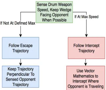
The goal of the autonomous system is to drive the robot better than a user would. Higher complexity locomotion algorithms will be used to give the combat robot a significant edge above all manual robots. This will be done by implementing two algorithms for movement. The first being a intercept or escape algorithm. The second being an algorithm that utilizes the robot’s weapon design, which will attempt to keep the defensive wedge pointed at the opponent at all times.
The intercept or escape algorithm will determine if the robot should be avoiding or attacking the opponent. This will be dependent on if the chosen drum is at a sufficient velocity, or at least will be at sufficient velocity by the time it reaches the opponent. If the robot’s drum weapon is at a acceptable speed, or the opponent is far enough away, the robot will use a simple tracking algorithm and traverse directly toward the opponent..
When the drum is not at full speed, and the opponent is nearby, the combat robot will use the escape algorithm. This algorithm is based on an optimal escape pattern in which the trajectory vector is set perpendicular to the current locomotion vector of the opposing robot. This will successfully escape the opponents so the drum weapon can obtain optimal speed. These algorithms will outperform manual operators as long as the speed of the robot is near or above the opponent. The full algorithm is shown below in figure 1.
The opponent facing tracking algorithm will implement a defensive strategy used by human wedge operators. The strategy is to keep the wedge always facing the opponent. This will cause the attacking opponent to drive on top of the wedge, and potentially flip over, when attempting to attack. While on top of the autonomous combat robot, the attacking robot’s weapon system is less likely to hit the autonomous robot. Also giving it an opening to attack using the drum weapon.
Figure 1: Autonomy Locomotion Algorithm.
[CH]
1.5 Marketing Requirements
The marketing requirements for the combat robot system are as follows:
1. The robot shall operate autonomously.
2. The sensor system shall read environment data to be sent to the autonomy system.
3. The autonomy system shall be able to differentiate between the arena walls and the enemy. 4. The autonomy system shall be able locate the enemy with respect to itself.
5. The autonomy system shall be able to make a fight or flight decision.
6. The autonomy system shall output a recommended location where the robot should travel. 7. The recommended location shall include the orientation to keep the enemy in front of the
robot when possible.
8. The autonomy system shall easily interface with the system of The Motion and Actualization Team.
9. The autonomous system shall indicate if the system is still functional. 10.The robot shall be compliant with all other RoboGames rules [15].
[SV, FA, CH, TT, TW, SV, HL]
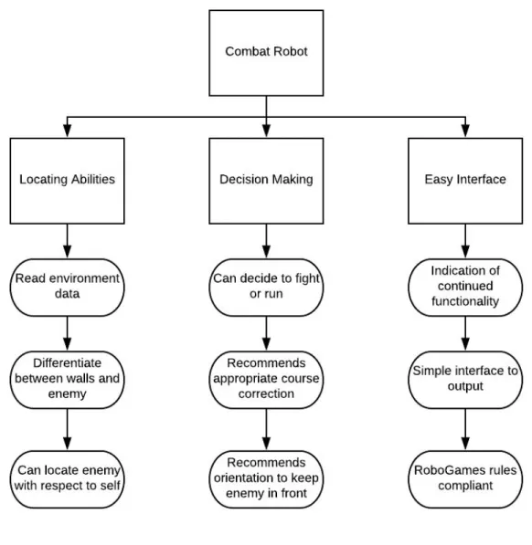
1.6 Objective Tree
The objective tree for the fully autonomous combat robot is shown in Figure 2 below. This was derived from the marketing requirements.
Figure 2: Combat Robot Autonomy Objective Tree.
[SV]
2.0 Design Requirements Table 2: Design Requirements Marketing
Requirement
Engineering Requirements Justification
9, 8 1. The autonomous system shall visually report the functionality of the
autonomous system.
The operator of the robot must know when to switch to manual mode if the autonomous system fails.
3,4 2. The autonomous system shall visually report if an enemy is detected.
This should be done in order to verify that the movements/actions of the robot are due to the
autonomous system. 5 3. The autonomous system shall visually
report whether it is in fight, flight, or search mode.
This should be done in order to verify that the robot is following the correct course of action.
11 4. The robot and autonomy system shall operate for three minutes without interruption.
The length of a RoboGames match is three minutes. The robot must operate for the entirety of the match.
1,6,7,8 5. The autonomous system shall continuously output the recommended angle and speed (to the motion and actualization system).
The autonomous system should instruct the motor control system to charge or search for an
opponent when possible (see 6). 1,10 6. The autonomous system shall sense
and output a signal if the robot gets flipped over from its original orientation (to the motion and actualization system).
The autonomous system should stop operation if the robot has been flipped over.
1,2,4 7. The autonomy system shall be able to detect an object up to 12 meters away (within the field of view).
In order to effectively defend itself from an attacker and to effectively attack, the robot needs at least twelve meters to prepare. 1,2,4 8. The system must report the location
of a detected enemy with no more than 5 degrees error from 20 feet away.
In order to accurately determine the recommended location, the robot needs to know where the enemy is.
1,7 9. The autonomous system shall The robot needs to be ready to 24
initialize within 60seconds of the robot being powered up.
defend/attack at the start of the match.
11 10. The autonomous system shall weigh less than 6 pounds.
The robot shall be classified as a 60 lb combat bot and the rest of the components have been allotted the other 54 lbs.
11 11. The emergency stop shall power off and stop the autonomous system within 60 seconds.
RoboGames rules state that the robot should be powered off completely within sixty seconds. 8 12. The system shall have overcurrent
protection on each board for 110% of the max current.
In order to protect the rest of the robot from malfunction, the robot shall not be allowed to draw more current than the power supply can provide.
8 13. The system shall operate on less than 144 watts.
The power supply is to be able to supply 144 to the autonomous system.
1,5 14. Robot shall not engage enemy unless the weapon ready signal has been
received.
In order to effectively attack an enemy, the weapon needs to have enough momentum to do damage.
3.0 Accepted Technical Design
The sections below show system block diagrams broken down by sections.
[HL]
3.1.1 System Level 0 Block Diagram with Functional Requirement Table
Figure 3: DT7A Autonomous System Block Diagram
[HL]
The level 0 functional requirement table, indicating the top-level inputs and outputs of the fully autonomous combat robot, as shown in Table 3 below.
Table 3: Level 0 Functional Requirement Table
Module Combat Robot
Inputs ● LiDAR Input Signal
● Ultrasonic Sensor Input Signal ● Motor Encoder Input Signal ● Gyroscope Input Signal
Outputs ● Recommended Position for Robot Output: UART (output to the controller board from DT07B)
● Functionality Output: LED Light
Functionality Determines the recommended position for the robot using an algorithm that uses the data from the sensors. This system also determines and indicates whether the autonomous system (as a whole) is functioning.
[FA, CH, HL]
3.1.2 Hardware Level 1 Block Diagram with Functional Requirement Table
The level 1 block diagram, which is an expansion of the level 0 diagram in Figure 2, is shown in Figure 4.
Figure 4: Level 1 Combat Robot Block Diagram.
[CH, HL]
The level 1 functional requirement table, indicating the second-level inputs and outputs of the fully autonomous combat robot, as shown in tables 4 and 5 below.
Table 4: Hardware Level 1 Sensor Array Functional Requirement Table.
Module Robot Sensor System Inputs ● Sensor Input Signals
Outputs ● Proximity and Orientation data
Functionality Senses the location of the opposing robot and nearby walls. Outputs this information to the Navigation Center.
[HL] Table 5: Hardware Level 1 Robot Control Center Functional Requirement Table.
Module Robot Navigation Center
Inputs ● Proximity and Orientation data ● Orientation
● Encoder Feedback Outputs ● Recommended Position
● Autonomous Enable/Emergency Stop
Functionality Processes data from sensor system and makes autonomous fight or flight decisions. Produce a recommended location and orientation signal to send to controller.
[FA, CH ]
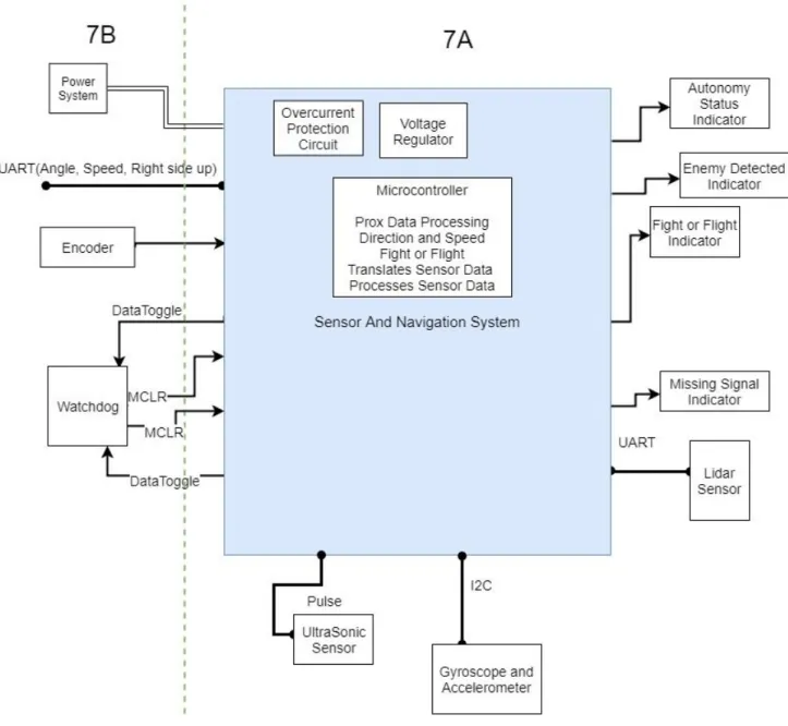
The second level hardware diagram for the autonomous section of the combat robot is shown below. Items the left of the green dotted line are components of design team 7Bs system in which we will interact with.
3.1.3 Hardware Level 2 Block Diagram with Functional Requirement Table
Figure 5 - Hardware Level 2 Block Diagram
[CH,HL] Table 6: Ultrasonic Sensor Functional Requirement Table.
Module Ultrasonic Sensor
Inputs ● Environmental data
Outputs ● Varying Pulse
Functionality The ultrasonic sensor measures distances by sending an ultrasonic pulse and waiting for an echo. The sensor then returns a value that reflects the time between the emitted pulse and the echo.
[HL] Table 7: Gyroscope Functional Requirement Table.
Module Gyroscope and Accelerometer Sensor Inputs ● Environmental data
Outputs ● I2C axial rotation and acceleration data
Functionality The gyroscope and accelerometer will give data feedback on the robots motion containing G force information and angular rate information.
[CH]
Table 8: Lidar Sensor Functional Requirement Table. Module Lidar Sensor
Inputs ● Environmental data
● PWM Motor Control Signal Outputs ● Angle and distance over UART
Functionality The Lidar sensor measures distances using a laser and measuring the reflection. It uses the reflection to detects object and output an angle and distance of their location.
[HL]
Table 9: Sensor System Functional Requirement Table. Module Sensor System Microcontroller
Inputs ●
Outputs ● Enemy Position and Wall Position: UART (To the Robot Navigation Center),
● Gyroscope and Accelerometer data in UART ● Ultrasonic sensor data
Functionality
[CH]
Table 10: Overcurrent Protectors Functional Requirement Table. Module Overcurrent Protectors (One for each board) Inputs ● Voltage from battery
Outputs ● Separate power supply for the navigation and sensor boards
Functionality The overcurrent protectors break the circuit if the boards draw more than their allotted current.
[HL] Table 11: Level 2 Voltage Regulators Functional Requirement Table.
Module 3.3 V And 5 V Voltage Regulators
Inputs ● 24 volt input
Outputs ● 3.3 volt and 5 volt outputs
Functionality The voltage regulators take a 24 volt input and regulate it down to 3.3 v and 5 v to power the sensors and microcontrollers.
[HL]
Table 12: Level 2 LED Lights Functional Requirement Table.
Module LED Lights
Inputs ● Microprocessor outputs
Outputs ● LED lights
Functionality The LED lights are used to visually indicate the autonomy status, enemy detection, fight or flight and missing signal.
[HL]
Table 13: Sensor System Functional Requirement Table. Module Navigation/Sensor System Microcontroller
Inputs ● Sensor Input Signal: UART from Lidar, Pulse for Ultrasonic, and I2C Gyroscope
● Motor Encoder Input Signal Outputs ● Recommended angle in UART
● Recommended speed setting in UART
● If the robot is right side up (Manual override is needed if the robot is flipped)
Functionality The navigation/sensor system microcontroller will process the proximity data from the sensors. It will differentiate between the enemy and walls. The microcontroller will determine if high or low speed should be used and a angle to travel.
[CH]
3.1.4 Hardware Level 3 Diagram (Schematic Design)
The schematic of the sensor and navigation board is shown below. The microprocessor will be programed in C.
Analysis on the clock cycle level lets us conclude that all of the Sensor and Navigation systems processing could be completed on one PIC32MZEF processor due to its speed and storage. With the speed of the processor being 252MHz, the time required for each navigation loop is estimated below:
● Read from LiDAR (50ms)
● Process LiDAR data (<1ms, 100 cycles) ● Check gyroscope (<1ms, 100 cycles)
● Check ultrasonics (if necessary) (1ms - 18.5ms, time hi and time low) ● Check encoders (if necessary) (<1ms, 100 cycles)
● Make path decision (<1ms, 100 cycles) ● Update current path (<1ms, 100 cycles)
All of these times add up to less than 50ms, with the fast speed of the processor this allows us to complete all of the other processes while reading from the LiDAR. Further analysis has been done in calculations section 3.5.4. Based on these calculations, the baud rate required of the sensors is at least 20 MHz, the processor will accommodate this because its equivalent speed of reading is 63MHz.
Analysis was also done on the system to choose the processor. For ease of communications
and programming the same processor will be used for both design team 07A and 07B. Therefore, the processor chosen must be capable of performing the necessary tasks for each team independently. The full combat robot system of both teams requires 3 UART modules (to communicate between the boards and to the LiDAR), a I2C module (to communicate to the accelerometer/gyroscope), 8 PWM capture compare modules (for the RC receiver and to drive the LiDAR motion), preferable USB capable (for troubleshooting), and at least 102,400 bytes of RAM flash memory (to store the sensor data). This is because the lidar needs to store 3200 bytes and we would like to store at least 4 samples in order to plan a path. This is calculated from 800 bytes of distance data plus 800 bytes of angle data per scan, multiplied by two additional data arrays to store processed data which will enable the robot to locate the enemy. This results in 3200 bytes, or 25,600 bits.
Multiple processors were found to meet these requirements. PIC32MX795F512H-80V appeared that it could meet our requirements, but its processors speed is only 80 MHz and its memory is 128 KB. The PIC32MZ2048EFH064 was chosen because for only $1.85 more the processor is faster, 252Mhz, and the memory is larger, 512 KB.
LED’s 0 through 8 will be used as indicators. LED 0-4 will report if the functionality (if autonomy can or cannot be used), if a enemy is detected, is none of the sensors are giving meaningful feedback, and if the system is in fight or flight mode. LED 9 an 10 will be used to indicate if our board has power.
The accelerometer outputs data in I2C to the processor. This will be interpreted and used to determine how the robot will need to move it's motors to navigate. If the robot is upside down the motor directions will need flipped. The LiDAR, which communicates in UART, will be used to determine the enemies location. The ultrasonic sensor, which returns a hi to low time ratio, will be
used as a redundancy to determine the enemies location. The signal from the ultrasonic sensor will be interpreted using the input compare module and a timer to calculate the ratio between hi and low time. This will let us determine the distance measured to the detected object.
The sensor and navigation board will communicate to The Motion and Actualization Team in UART. The RX of our system will connect the the TX of there system and vice versa. An external oscillator will be used on the processor due to the sensitivity to UART to timing and the inaccuracy of internal oscillator in microcontrollers.
The Motion and Actualization Team will be providing power to the system. The power to our Sensor/Navigation board will be fully isolated from The Motion and Actualization Team’s system. There is DC/DC isolation on the power source and isolation on the signals between the 2 boards. A backplane/card edge system will be used to interface with the hardware of The Motion and
Actualization Team systems.
The sensors connections will be broken out directly to each sensor for testing purposes. In the final system they will be then routed through the backplane of 7B’s system to the sensors to decrease noise and save space from less wiring needed.
All motion will cease within a minute after the emergency stop is pressed on The Motion and Actualization Team’s system. This was tested by powering the lidar down while at full spin. It took 2.5 seconds for the lidar to stop rotating when powered down at a full speed spin. A USB interface has been added to the board for the purpose of ease of reading date from the sensor/navigation microcontroller. Unused pins are labeled with their communication protocol peripheral or other functionality for ease of addition of other hardware to the sensor and navigation schematic.
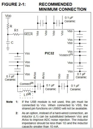
The minimum schematic for the microcontroller is shown below is shown below. The
decoupling capacitors are implemented in the circuit schematic that was designed. The suggested value of 0.1uF is used. This operates as a low pass filter. The trace has around 0.1 ohms, this results in a filter with a corner frequency of 16 MHz.
Figure 6: Minimum Hardware Schematic
[CH]
Figure 7: Schematic Diagram of the Sensor And Navigation System
[CH]
The board file is shown below for the sensor and navigation board.
Some specific notes about this design are, the current through the indicator LEDs are set to 15mA to light the leds bright enough to be seen across the room. This was calculated with the equation below. 6.67≃90Ohms R= I LED VS−VLED = 0.0153.3−2 = 8 95≃400Ohms R= I LED VS−VLED = 5−2 0.005 = 3
The current for the pullup of the master clear was calculated to be 0.33mA, this is a high enough current for the CMOS technology of our microcontroller.
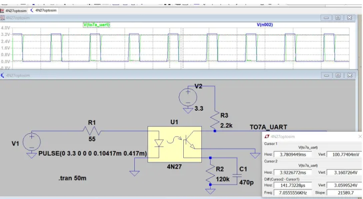
3.1.5 Hardware Simulation
There was a concern that the optical isolation would add too much delay to the uart communication. Because of this a simulation was performed on the optical isolation in order to optimize the circuit for low delay. This simulation is shown below. R1 sets the forward current of
the diode to 60mA as specified from the datasheet. A 2.2k standard pull up is used for the signal. R2 sets the sensitivity of the phototransistor. The capacitor is added to prevent unwanted turn ons due to noise from outside light or electromagnetic interference.
Figure 8: Optoisolator simulation
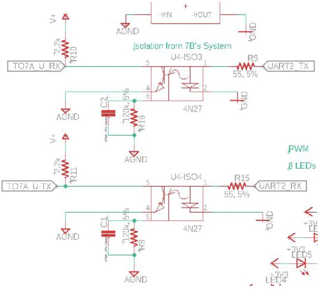
The design implemented on the eagle schematic is shown below. GND is our isolated systems ground and AGND is the ground from the robot power system.
[CH]
Figure 9: Optical Isolator Design
The Harmony Configurator system add on to MPLABX is a configuration system created by microchip in order to program the PIC32 series processors. Microchip has limited support for programming these series of processors using the classical coding method of configurations words and bitwise setting of configuration registers. To solve this problem Microchip created the Harmony Configuration system, which creates the configuration files for the PIC32 processors. The Harmony graphical user interface for the PIC32MZ2048EFH064 is show below in figure 10. This GUI allows the user to configure the pins with the desired internal peripherals.
Figure 10: Harmony GUI for PIC32MZ2048EFH064
3.1.6 Hardware Testbench
In order to begin Hardware test benching a 100 pim PIM with the PIC32MZEF family microcontroller. This PIM was plugged into the Explorer 16/32 board. The processor then was configured using the Harmony Configurator shown below in Figure 11.
[CH]
Figure 11: 100 pin PIM for PIC32MZEF
The microcontroller and its configuration using Harmony was tested by blinking a LED. This was successful. The next task was to begin testing with the sensors. Configuration with the LiDAR was determined.
In order to spin the lidar, it was necessary to generate a 25kHz PWM signal using the PIC24MZ PIM on an Explorer 16/32 board. To accomplish this, a timer was set up using a 16 prescaler on the 252MHz clock. This gave a timer frequency of 252MHz/16= 15MHz. This timer
was then used to set up a PWM with a period of 600 timer counts which is equivalent to a period of 25kHz. An output compare pulse width of 360 timer counts yields a 60% duty cycle which is nominal for 10Hz rotation of the RPLiDAR A3. Figure 12 shows the PWM output of the Explorer 16/32 board.
Figure 12: 60% duty cycle PWM output, 25kHz
[SV, HL, CH]
3.1.7 Software Level 0 Block Diagram and Functional Requirements Table
The software system is described in the preceding sections. The zero level block diagram is shown below.
Figure 13: Software Level 0 Block Diagram
[FA] Table 14: Software System Functional Requirement Table
Module Software System
Inputs ● Environment
Outputs ● Recommended Robot Action
Functionality The software system must collect data from the environment and use that data to determine a course of action for the robot. A course of action will be a direction and speed for the robot to travel and will constitute a fight or flight command.
[FA, SV] 3.1.8 Software Level 1 Block Diagram and Functional Requirement Tables
Figure 14: Software Level 1 Block Diagram
[SV]
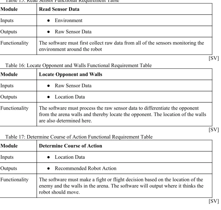
Table 15: Read Sensor Functional Requirement Table Module Read Sensor Data
Inputs ● Environment
Outputs ● Raw Sensor Data
Functionality The software must first collect raw data from all of the sensors monitoring the environment around the robot
[SV] Table 16: Locate Opponent and Walls Functional Requirement Table
Module Locate Opponent and Walls
Inputs ● Raw Sensor Data
Outputs ● Location Data
Functionality The software must process the raw sensor data to differentiate the opponent from the arena walls and thereby locate the opponent. The location of the walls are also determined here.
[SV] Table 17: Determine Course of Action Functional Requirement Table
Module Determine Course of Action
Inputs ● Location Data
Outputs ● Recommended Robot Action
Functionality The software must make a fight or flight decision based on the location of the enemy and the walls in the arena. The software will output where it thinks the robot should move.
[SV]
3.1.9 Level 2 Software Block Diagram
Figure 15: Software Level 2 Block Diagram
[FA, SV] Table 18: Initialize Sensors Requirement Table
Module Initialize Sensors
Inputs ● Machine Power Up
Outputs ● Sensors Ready Signal
Functionality When the machine is powered up, start up the LiDAR and ultrasonic sensors. Proceed once data can be reliably read from both.
[FA, SV] Table 19: Read Data Functional Requirement Table
Module Read Data
Inputs ● Sensors Ready Signal
● Read Sensors Signal
Outputs ● Raw Sensor Data
Functionality Reads data from the LiDAR and ultrasonic sensors, first when the sensors are started and again every time the current data has been processed. Returns raw data from the sensors.
[FA, SV]
Table 20: Interpret Data Functional Requirement Table Module Interpret Data
Inputs ● Raw Sensor Data
Outputs ● Wall or Opponent Location
Functionality Checks the LiDAR data for anomalies and analyzes their shape to determine if it is looking at a wall or an opponent. For each anomaly, the data is sent to be processed for decision making.
[FA, SV] Table 21: Calculate Fight or Flight Functional Requirement Table
Module Calculate Fight or Flight
Inputs ● Wall or Opponent Location
Outputs ● Location Data
● Speed Data
Functionality If an opponent is detected, makes decision to either run towards or away from it. If a wall is detected, makes decision to turn away from it. If nothing is detected, makes decision to turn until something is detected.
[FA] Table 22: Update Encoded Location/Speed Functional Requirement Table
Module Update Encoded Location/Speed
Inputs ● Location Data
● Speed Data
Outputs ● Encoded Location/Speed Data ● Read Sensors Signal
Functionality Convert the location and speed decision to a UART data packet to be read by Team B. Read updated data from the sensors.
[FA]
3.1.10 Level 3 Software Block Diagram
Figure 16: Level 3 Software Block Diagram
[FA]
3.2.0 Sensor Block Diagrams and Software 3.2.1 Main Program Software
main.c: controls the operation of the program
#include <stddef.h> // Defines NULL #include <stdbool.h> // Defines true
#include <stdlib.h> // Defines EXIT_FAILURE #include "system/common/sys_module.h" // SYS function prototypes int AssertFlag;
int main ( void ) {
/* Initialize all MPLAB Harmony modules, including application(s). */ // Start: //goto jump for timer done
SYS_Initialize ( NULL );
while ( true ) {
/* Maintain state machines of all polled MPLAB Harmony modules. */ SYS_Tasks ( );
}
/* Execution should not come here during normal operation */ return ( EXIT_FAILURE );
}
app.h: header file for UART communication
#include <stdint.h> #include <stdbool.h> #include <stddef.h>
#include <stdlib.h> #include "system_config.h" #include "system_definitions.h" #include "system_config/default/system_config.h" #include "autonomy.h" #include "lidar.h" #include "led.h" #include "ultrasonic.h" #include "gyroscope.h" #include "timers.h" typedef enum {
/* Application's state machine's initial state. */ APP_STATE_INIT=0,
APP_STATE_SERVICE_TASKS,
/* TODO: Define states used by the application state machine. */
} APP_STATES; typedef struct {
/* The application's current state */ APP_STATES state;
/* TODO: Define any additional data used by the application. */
} APP_DATA;
void APP_Initialize ( void );
void APP_Tasks( void );
app.c: source file for UART communication #include "app.h" APP_DATA appData; lidarData lData; short uartAngle; short uartDrive; DRV_HANDLE teraHandle; DRV_HANDLE teraHandle1; DRV_USART_TRANSFER_STATUS status; DRV_USART_TRANSFER_STATUS status1; size_t count; size_t count1; char send[100]; short sendB[2] = {1,0}; char receive[100]; timers_t ms100; int sample = 0;
void APP_Initialize ( void ) {
/* Place the App state machine in its initial state. */
SYS_INT_Enable(); DRV_IC0_Start(); DRV_IC1_Start(); DRV_IC2_Start(); DRV_TMR0_Start(); DRV_TMR1_Start(); DRV_TMR2_Start(); DRV_OC0_Start(); 52
DRV_OC1_Start(); DRV_OC2_Start(); setTimerInterval(&ms100, 256); ledAllOn(); delay(1000); DRV_USART_Initialize; ledAllOff(); initLidar(); initUltras(); initGyro(); appData.state = APP_STATE_INIT; }
void APP_Tasks ( void ) {
/* Check the application's current state. */ switch ( appData.state )
{
/* Application's initial state. */ case APP_STATE_INIT:
{
bool appInitialized = true;
if (appInitialized) { appData.state = APP_STATE_SERVICE_TASKS; } break; } 53
case APP_STATE_SERVICE_TASKS: {
// while (1) {
int counter = millis();
//send[0] = readAngleX();
//Gets information about opponent and walls via LiDAR
statusOn(); //LED_debug1On(); lData = getLidarData(); statusOff(); //LED_debug1Off();
//Autonomous path decision
path dir = getPath(lData);
if (dir.angle == 0) { uartAngle = 183; } else { uartAngle = dir.angle; } uartDrive = dir.drive; //BSP_Initialize(); // LED_debug2On(); int num1=getUltrasData(0); int num2=getUltrasData(1); 54
//LED_debug2Off(); //LED_debug3On();
int num3=976562.5*0.5/(Get_Encoder_Data ()); //LED_debug3Off();
//LED_debug4On(); int num4 = readAngleX(); //LED_debug4Off(); //int num4 = 0;
//lData = getLidarData();
int num5 = lData.opponentDistance; int num6 = lData.opponentAngle; sendB[0] = dir.angle;
//int num7 = (int)dir.angle; //int num8 = (int)dir.drive;
// PORTE = ~lData.opponentDistance>>5; /* if(sendB[0]>=179) { sendB[0] = 1; } if(sample >= 10) { sendB[0]+=1; sample = 0; } sample++; * */ //sendB[0]=183;//dir.angle; //num7; sendB[1]=dir.drive; //num8; 55
sprintf(send,"Ultrasonic Right = %i Ultrasonic Left = %i Encoder = %i RPM Gyroscope =
%i Lidar = %i Counter = %i UARTB = %i %i\n\r",num1,num2,num3,num4,num6,counter,sendB[0],sendB[1]);
teraHandle = DRV_USART_Open(DRV_USART_INDEX_0, DRV_IO_INTENT_WRITE); //open tera usart channel
count = DRV_USART_Write(teraHandle, send, strlen(send)); //write to tera DRV_USART_Close(teraHandle); //discard tera handle
/*
teraHandle=DRV_USART_Open(DRV_USART_INDEX_0,DRV_IO_INTENT_READWRITE); count = DRV_USART_Read(teraHandle, receive, 1); //write to tera DRV_USART_Close(teraHandle); //discard tera handle
// Encodes UART
// Software patch for errors caused by sending 0 over UART */
teraHandle1 = DRV_USART_Open(DRV_USART_INDEX_2, DRV_IO_INTENT_WRITE); //open tera usart channel
count1 = DRV_USART_Write(teraHandle1, sendB, 4); //write to tera DRV_USART_Close(teraHandle1); //discard tera handle
//ledAllOff(); // } break; }
/* TODO: implement your application state machine.*/
/* The default state should never be executed. */ default:
{
SYS_RESET_SoftwareReset();
/* TODO: Handle error in application's state machine. */ break;
} } }
autonomy.h: header file for fight or flight decision
#include "lidar.h" #include "system_config.h" #include <stdint.h> #include <stdbool.h> #include "system_config/default/system_config.h" typedef struct { short angle; short drive; } path;
path getPath(lidarData lData);
autonomy.c: source file for fight or flight decision
#include "app.h" #include "autonomy.h" #include "gyroscope.h" #include "ultrasonic.h" #include "encoder.h" #include "led.h" #include "system_config/default/system_config.h" #include "system_config.h" 57
// Keeps track of where to search if LiDAR goes missing unsigned short lastKnownAngle;
unsigned short lastKnownDistance; unsigned short forwardCounter;
path getPath(lidarData lData){
path dir;
// Sends designated signal to indicate upside down if (isUpsideDown() == true) { dir.angle = 183; //Manual dir.drive = 183; return dir; }
///Preprocessing LiDAR data // Converts angles 0-90 to 90-180 lData.opponentAngle += 90;
// Converts angles 270-359 to 0-89
if (lData.opponentAngle >= 360) lData.opponentAngle -= 360; // Contrains angles between 1-179 to avoid complications if (lData.opponentAngle == 0) lData.opponentAngle = 1; if (lData.opponentAngle >= 180) lData.opponentAngle = 179;
// If the enemy could not be spotted with LiDAR if (lData.opponentDistance == 0) {
forwardCounter += 1; //flightOff();
// If the enemy is spotted by ultrasonics, go straight forward if (isUltraClose() ||
((lastKnownDistance < 1000) && (forwardCounter < 10) && ((lastKnownAngle >= 80) || (lastKnownAngle <= 100)))) {
enemyOn(); missingOff(); dir.angle = 90;
dir.drive = 182; //Forward return dir;
} else { // If nothing is detected, go into search mode flightOn(); enemyOff(); missingOn(); dir.drive = 181; //Search if (lastKnownAngle < 90) dir.angle = 1; else dir.angle = 179; flightOff(); } } else {
// If the enemy is found, go into fight or flight mode forwardCounter = 0; enemyOn(); missingOff(); // Fight logic if ((isWeaponReady()) || (lData.opponentDistance > 10000)) { flightOff(); dir.angle = lData.opponentAngle; dir.drive = 182; // Flight logic } else { flightOn(); dir.drive = 184; dir.angle = 90;
// Make an 80 degree turn away from opponent //if (lData.opponentAngle < 90) {
// dir.angle = lData.opponentAngle + 80; //} else {
// dir.angle = lData.opponentAngle - 80; //} } } lastKnownAngle = dir.angle; if (lData.opponentDistance != 0) { lastKnownDistance = lData.opponentDistance; } return dir; }
timers.h: header file for internal clocks and timers
#include <stdbool.h> #include <stdlib.h>
typedef struct {
unsigned long timerInterval; unsigned long lastMillis; } timers_t;
bool timerDone(timers_t * t);
void setTimerInterval(timers_t * t, unsigned long interval); void resetTimer(timers_t * t);
void globalTimerTracker( ); unsigned long millis(void); void delay(unsigned int val); void isTimedOut(void);
timers.c: source file for internal clocks and timers
#include "timers.h"
unsigned long globalTime; timers_t timeOut;
unsigned long millis(void) { return globalTime; } bool timerDone(timers_t * t) {
if(abs(millis() - t->lastMillis) > t->timerInterval) { t->lastMillis=millis(); return true; } else { return false; } }
void setTimerInterval(timers_t * t, unsigned long interval) { t->timerInterval= interval; } void resetTimer(timers_t * t) { t->lastMillis=millis(); } 61
//Call this function in your timer interupt that fires at 1ms void globalTimerTracker( ) { globalTime++; } timers_t time;
void delay(unsigned int val) { setTimerInterval(&time,val); int i; while(!timerDone(&time)) { i++; } }
// Triggers if the component fails to connect void isTimedOut() { setTimerInterval(&timeOut,100); while(!timerDone(&timeOut)) missingOn(); missingOff(); }
led.h: header file for enabling and disabling LEDs
void ledAllOff(void); void ledAllOn(void);
void binaryOutput(unsigned short input); void enemyOn(void);
void flightOn(void);
void missingOn(void); void statusOn(void); void debug1On(void); void debug2On(void); void debug3On(void); void debug4On(void);
led.c: source file for enabling and disabling LEDs
#include "led.h" #include "app.h" #include "system_config.h" void ledAllOn(void) { LED_EnemyOn(); LED_FlightOn(); LED_MissingOn(); LED_StatusOn(); LED_debug1On(); LED_debug2On(); LED_debug3On(); LED_debug4On(); } void ledAllOff(void) { LED_EnemyOff(); LED_FlightOff(); LED_MissingOff(); LED_StatusOff(); LED_debug1Off(); 63
LED_debug2Off(); LED_debug3Off(); LED_debug4Off(); }
void binaryOutput(unsigned short input) { if (input & 0b0001) { LED_debug1On(); } if (input & 0b0010) { LED_debug2On(); } if (input & 0b0100) { LED_debug3On(); } if (input & 0b1000) { LED_debug4On(); } } void enemyOn(void) { LED_EnemyOn(); } void enemyOff(void) { LED_EnemyOff(); } void flightOn(void) { 64
LED_FlightOn(); } void flightOff(void) { LED_FlightOff(); } void missingOn(void) { LED_MissingOn(); } void missingOff(void) { LED_MissingOff(); } void statusOn() { LED_StatusOn(); } void statusOff() { LED_StatusOff(); } void debug1On(void) { LED_debug1On(); } void debug1Off(void) { LED_debug1Off(); } void debug2On(void) { LED_debug2On(); 65
} void debug2Off(void) { LED_debug2Off(); } void debug3On(void) { LED_debug3On(); } void debug3Off(void) { LED_debug3Off(); } void debug4On(void) { LED_debug4On(); } void debug4Off(void) { LED_debug4Off(); } 66
3.2.2 LiDAR Sensor
A LiDAR emits an infrared laser which bounces off of the nearest object to measure the distance to the nearest object. The robot will use a rotating LiDAR sensor to locate objects in the arena, specifically the enemy. The requirements for the LiDAR are listed in Table 23, and are based on the simulations detailed in 3.5.1 and 3.5.2 below
Table 23:LiDAR Sensor Requirements
Desired RPLiDAR A3
Maximum sensing distance 17m 20m
Minimum sensing distance 3m 1m
Sample Rate 8kHz 16kHz
Cost As small as possible $600
Table 23 shows that the RPLiDAR A3 fulfills the basic requirements for resolution and sensing distance. It was selected because it was the cheapest available option that fulfilled the minimum requirements.
As the RPLiDAR A3 spins, it returns ordered pairs consisting of the distance to the nearest object, as well as the angle to that object. The robot will be programmed to process this data to search for anomalies consistent with an opponent in the arena. Figure 17 shows a flow chart representing the LiDAR interface process.
[SV]
[SV] Figure 17: RPLiDAR Interface Flowchart
Below, the software is shown for the LiDAR sensor. The software shows the process for reading values and determining an opponent angle and distance.
lidar.h: header file for the LiDAR sensor
#include "system_config.h"
#include "system_config/default/system_config.h"
// Return the closest point of the opponent and the wall // If none detected, return 0
typedef struct {
unsigned short opponentAngle; unsigned short opponentDistance; unsigned short wallAngle; unsigned short wallDistance; } lidarData;
void firstFilter(int sampleSpace); void secondFilter();
void thirdFilter(int sampleSpace); void isLidarTimedOut();
lidarData getLidarData(void);
void setLidarData(short oppAng, short oppDist, short wallAng, short wallDist); void initLidar(void);
lidar.c: source file for the LiDAR sensor
#include "lidar.h" #include "app.h" #include "led.h" // Example data lidarData lidar = {0, 0, 0, 0}; 69
//global variables DRV_HANDLE lidarHandle; DRV_HANDLE teraHandle2; DRV_USART_TRANSFER_STATUS status; timers_t timeOut;
unsigned char readBuffer[1852]; unsigned char writeBuffer[2]; size_t count_1, total;
int count1, corner_index, front_corner_index; unsigned short extractAngle[369];
unsigned short extractDistance[369]; unsigned short firstDifference[369]; unsigned short secondDifference[5];
unsigned short outputAngleDistance[4] = {0,0,0,0}; unsigned short wallDistance = 0, wallAngle = 0;
unsigned short startArray = 0xa520;
int start = 0,found_A_Quality_Index = 0, n_samples_apart; int sample_threshold[10] = {600, 600, 300, 400, 500, 600, 900, 1000, 1300, 600}; /*int sample_threshold_2 = 600; int sample_threshold_3 = 300; int sample_threshold_4 = 400; int sample_threshold_5 = 500; int sample_threshold_6 = 600; int sample_threshold_7 = 900; int sample_threshold_8 = 1000; int sample_threshold_9 = 1300; 70
int sample_threshold_10 = 600;*/ int Found_Enemy = 0;
int j;
void firstFilter(int sampleSpace) { for(j = sampleSpace + 4; j < 360; j++) {
//we suspect a zeroed value is why we returned zero
if(extractDistance[j]>extractDistance[j-sampleSpace] && extractDistance[j-sampleSpace]!=0 ) { firstDifference[j] = extractDistance[j]-extractDistance[j-sampleSpace]; //secondDifference[j] = extractDistance[j-1]-extractDistance[j-2]; if(firstDifference[j]>sample_threshold[sampleSpace - 1] ) { outputAngleDistance[0] = extractAngle[j]; outputAngleDistance[1] = extractDistance[j-sampleSpace]; corner_index = j; n_samples_apart = sampleSpace; } } } } void secondFilter(){
secondDifference[0] = extractDistance[corner_index - n_samples_apart] - extractDistance[corner_index - (n_samples_apart+1)];
secondDifference[1] = extractDistance[corner_index - n_samples_apart] - extractDistance[corner_index - (n_samples_apart+2)];
secondDifference[2] = extractDistance[corner_index - n_samples_apart] -
extractDistance[corner_index - (n_samples_apart+3)];
secondDifference[3] = extractDistance[corner_index - n_samples_apart] - extractDistance[corner_index - (n_samples_apart+4)];
secondDifference[4] = extractDistance[corner_index - n_samples_apart] - extractDistance[corner_index - (n_samples_apart+5)]; if(secondDifference[0]<50||secondDifference[0]>65435 || secondDifference[1]<100||secondDifference[1]>65435 || secondDifference[2]<100||secondDifference[2]>65435 || secondDifference[3]<100||secondDifference[3]>65435 || secondDifference[4]<100||secondDifference[4]>65435) { Found_Enemy = 1; } } /*
void thirdFilter(int sampleSpace){
for(j = corner_index; j > sampleSpace + 1; j--) {
if(extractDistance[j]>extractDistance[j + sampleSpace] && extractDistance[j + sampleSpace] != 0) { firstDifference[j] = extractDistance[j] - extractDistance[j + sampleSpace]; if(firstDifference[j]>sample_threshold[sampleSpace - 1]) { outputAngleDistance[2] = extractAngle[j];
outputAngleDistance[3] = extractDistance[j + sampleSpace]; front_corner_index = j;
} }
} } */
// Triggers if the gyroscope fails to connect void isLidarTimedOut() { size_t count_L; char send_L[100]; DRV_HANDLE teraHandle_L; setTimerInterval(&timeOut,100); while(!timerDone(&timeOut)) { missingOn();
sprintf(send_L,"Lidar Communication Timeout Inside While Loop");
teraHandle_L = DRV_USART_Open(DRV_USART_INDEX_0, DRV_IO_INTENT_WRITE); //open tera usart channel
count_L = DRV_USART_Write(teraHandle_L, send_L, strlen(send_L)); //write to tera DRV_USART_Close(teraHandle_L); //discard tera handle
}
missingOff();
sprintf(send_L,"Lidar Communication Timeout Outside While Loop");
teraHandle_L = DRV_USART_Open(DRV_USART_INDEX_0, DRV_IO_INTENT_WRITE); //open tera usart channel count_L = DRV_USART_Write(teraHandle_L, send_L, strlen(send_L)); //write to tera
DRV_USART_Close(teraHandle_L); //discard tera handle }
// Temporary simulation until LiDAR is integrated lidarData getLidarData(void) { int i,j,k,look,start_index;//,corner_index,front_corner_index; lidar.opponentAngle = 0; lidar.opponentDistance = 0;
lidarHandle = DRV_USART_Open(DRV_USART_INDEX_1, DRV_IO_INTENT_READWRITE);