ARCHITECTING, PROGRAMMING, AND EVALUATING AN ON-CHIP INCOHERENT MULTI-PROCESSOR MEMORY HIERARCHY
BY WOOIL KIM
DISSERTATION
Submitted in partial fulfillment of the requirements for the degree of Doctor of Philosophy in Computer Science
in the Graduate College of the
University of Illinois at Urbana-Champaign, 2015
Urbana, Illinois
Doctoral Committee:
Professor Josep Torrellas, Chair and Director of Research Professor Marc Snir
Professor David Padua Professor William Gropp
Abstract
New architectures for extreme-scale computing need to be designed for higher energy efficiency than current systems. The DOE-funded Traleika Glacier architecture is a recently-proposed extreme-scale manycore that radically simplifies the architecture, and proposes a cluster-based on-chip memory hierarchy without hardware cache coherence. Programming for such an environment, which can usescratchpadsorincoherent caches, is challenging. Hence, this thesis focuses on architecting, programming, and evaluating an on-chip incoherent multiprocessor memory hierarchy.
This thesis starts by examining incoherent multiprocessor caches. It proposes ISA support for data movement in such an environment, and two relatively user-friendly programming approaches that use the ISA. The ISA support is largely based on writeback and self-invalidation instructions, while the program-ming approaches involve shared-memory programprogram-ming either inside a cluster only, or across clusters. The thesis also includes compiler transformations for such an incoherent cache hierarchy.
Our simulation results show that, with our approach, the execution of applications on incoherent cache hierarchies can deliver reasonable performance. For execution within a cluster, the average execution time of our applications is only 2% higher than with hardware cache coherence. For execution across multiple clusters, our applications run on average 20% faster than a naive scheme that pushes all the data to the last-level shared cache. Compiler transformations for both regular and irregular applications are shown to deliver substantial performance increases.
This thesis then considers scratchpads. It takes the design in the Traleika Glacier architecture and performs a simulation-based evaluation. It shows how the hardware exploits available concurrency from parallel applications. However, it also shows the limitations of the current software stack, which lacks smart memory management and high-level hints for the scheduler.
Acknowledgments
My PhD journey was full of challenges. I was able to overcome obstacles with help and support from many people. I would like to express my sincere gratitude to all of them.
First of all, I would like to thank my academic advisor, Professor Josep Torrellas. He helped me not only academically but also mentally. Weekly or more frequent meeting with him drove me to the right direction. His advice led me to the completion of PhD journey. His endless effort, pursuit of perfection, and enthusiasm for research will be my goal throughout my life.
I would also like to thank my committee members. Professor Marc Snir provided very critical but in-sightful comments that lead my thesis to the more complete and accurate form. Professor William Gropp also gave comments about the finest detail. Professor David Padua was with all my exams from the quali-fying exam to the final exam. Professor P. Sadayappan was a great collaborator and helper for many of my work. I cannot imagine my thesis without his help.
I also have to thank my collaborators in the projects that I was participated in. Sanket Tavarageri was a great collaborator. We shared lots of discussion and ideas, and his help was crucial in the completion of my work. Chunhua Liao was not only a nice collaborator but also a helpful mentor. I also want to mention Bala Seshasayee among X-Stack Treleika Glacier project members. His prompt answers and responses enabled progress in spite of many obstacles in the project.
My work would not be possible without help from IACOMA group members. I thank all IACOMA group members for their critical comments during the seminar and insightful suggestions. Besides, I thank Shanxiang, Yuelu, Prabhat, Tom, and Jiho for the time to chat about research, future, career, and culture. In fact, my PhD studies started from Wonsun’s help. I appreciate his help and hope a great success in his continuing academic journey.
Discussion with other friends in the same field was always fun and helpful. Heeseok listened to all my crazy ideas and provided precious comments. Neal helped me for soft-landing to the university research.
Yun helped me to verify my idea. Liwen was also a good discussion partner for everything.
I met many friends here in Champaign. The time with them supported me. I thank Soobae, Hyunduk, Jaesik, Jintae, Choonghwan, Hyojin, Daehoon, Minje, Kyungmin, and Daejun. Julie’s help for English and Professor Thomas Frazzetta’s kindness was another support for my life in Champaign. I also thank Rigel group members for their help.
I also appreciate help and support from colleagues and bosses in Samsung Electronics. Nakhee and Jinpyo have been always my role models in all aspects of research and development. I really thank my previous bosses, Seh-Woong Jeong, Jaehong Park, and Steve Kwon. Without their help, I could not even start my PhD journey.
Lastly, I thank my family. I especially thank my parents. Their endless devotion made me stand here. I appreciate all their help and dedicate this dissertation to them. I appreciate support from my wife Eunjeong. She made my life in Champaign complete and successful.
Table of Contents
List of Tables . . . viii
List of Figures . . . ix
Chapter 1 Introduction . . . 1
1.1 Motivation . . . 2
Chapter 2 Architecting, Programming, and Evaluating Incoherent Caches . . . 4
2.1 Basic Architectural Support . . . 4
2.1.1 Using Incoherent Caches . . . 4
2.1.2 Instructions for Coherence Management . . . 5
2.1.3 Instruction Reordering . . . 6
2.1.4 Synchronization . . . 8
2.2 Programming Model 1: MPI + Shared Intra Block . . . 9
2.2.1 Intra-block Programming . . . 10
2.2.2 Advanced Hardware Support . . . 13
2.3 Programming Model 2: Shared Inter Block . . . 15
2.3.1 Inter-block Programming . . . 16 2.3.2 Hardware Support . . . 20 2.4 Compiler Support . . . 21 2.5 Experimental Setup . . . 21 2.5.1 Area analysis . . . 22 2.6 Evaluation . . . 23
2.6.1 Performance of Intra-block Executions . . . 24
2.6.2 Performance of Inter-block Executions . . . 26
Chapter 3 Evaluating Scratchpads in Traleika Glacier . . . 28
3.1 Background for XStack . . . 30
3.1.1 Hardware architecture . . . 30
3.1.2 Software Platform . . . 30
3.1.3 Simulator . . . 33
3.2 Target Benchmark Program Study . . . 35
3.2.1 Cholesky . . . 35
3.2.2 Smith-Waterman . . . 37
3.2.3 FFT . . . 38
3.2.4 SAR . . . 39
3.3 Evaluation . . . 40
3.3.1 Performance Scaling . . . 40
3.3.2 Energy Consumption . . . 41
3.3.3 Effect of the Granularity of Parallelism . . . 43
3.3.4 Scheduling EDTs for Parallelism . . . 44
3.3.5 Multi-level Memory Allocation . . . 47
3.3.6 Estimation of Errors in Performance Simulation . . . 50
3.4 Future Directions . . . 52
Chapter 4 Related Work . . . 53
4.1 Software Cache Coherence . . . 54
4.2 Self-Invalidation-based Hardware Coherence Protocol . . . 56
4.3 Coarse-grained data flow execution . . . 58
Chapter 5 Conclusions . . . 61
Appendix A Compiler Support for Incoherent Caches . . . 62
A.1 Overview . . . 62
A.2 Background . . . 65
A.2.1 Execution Model . . . 65
A.2.2 Notation . . . 66
A.2.3 Polyhedral Dependences . . . 67
A.3 Compiler Optimization for Regular Codes . . . 68
A.3.1 Computation of Invalidate and Writeback Sets . . . 68
A.3.2 Optimization: Analysis Cognizant of Iteration to Processor Mapping . . . 70
A.4 Compiler Optimization for Irregular Codes . . . 72
A.4.1 Bulk Coherence Operations: Basic Approach . . . 72
A.4.2 Inspector-Executors . . . 72
A.4.3 Exclusion of Read-Only Data from Coherence . . . 74
A.5 Experimental Evaluation . . . 77
A.5.1 Benchmarks . . . 77
A.5.2 Set-up . . . 78
A.5.3 Performance Results . . . 79
A.5.4 Energy Results . . . 81
List of Tables
2.1 Classification of the benchmarks based on the communication patterns present. . . 13 2.2 Configurations evaluated. . . 21 2.3 Architecture modeled. RT means round trip. . . 22 3.1 Comparison of kernel programs (N is the problem size in one dimension, T is the tile size
in one dimension, and t is N/T, which is the number of tiles in one dimension.) . . . 40 A.1 Benchmarks. Legend: #PL: Number of Parallel Loops; #PLI: Number of Parallel Loops
containing irregular accesses . . . 76 A.2 Simulator parameters . . . 77
List of Figures
1.1 Runnemede chip architecture from [14]. . . 2
2.1 Communication between incoherent caches. . . 5
2.2 Ordering constraints. . . 7
2.3 Annotations for communication patterns enabled by: barriers (a), critical sections (b), flags (c), and dynamic happens-before epoch orderings (d). . . 9
2.4 Single block (a) and multi-block (b) cache hierarchy. . . 10
2.5 Enforcing data-race communication. . . 12
2.6 Example of level-adaptive WB and INV. . . 16
2.7 An iterative loop with irregular data references with the inspector. . . 19
2.8 Normalized execution time of the applications. . . 24
2.9 Normalized traffic of the applications. . . 26
2.10 Normalized number of global WB and INV. . . 27
2.11 Normalized execution time of the applications. . . 27
3.1 Hierarchical memory configuration (borrowed from the final report of [31]). . . 31
3.2 OCR dependency examples (borrowed from [31]). . . 32
3.3 FSim architecture model (borrowed from the final report of [31]). . . 33
3.4 FSim Timing Synchronization. . . 34
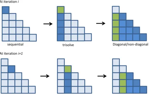
3.5 Cholesky algorithm. . . 36
3.6 Dependencies between EDTs in Cholesky factorization over iterations. . . 37
3.7 Dependence between EDTs in Smith-Waterman. . . 38
3.8 Concurrent execution of EDTs with diagonal parallelization and its expected scheduling on XEs. . . 38
3.9 Dependence between EDTs in FFT. . . 39
3.10 Dependence between EDTs in SAR. . . 40
3.11 Normalized execution time of the applications. . . 41
3.12 Energy consumption breakdown of the applications. . . 42
3.13 Normalized execution time with different tile sizes. . . 43
3.14 Normalized energy consumption breakdown with different tile sizes. . . 44
3.15 EDT scheduling timeline of Cholesky. . . 45
3.16 EDT scheduling timeline of Smith-Waterman. . . 46
3.17 DataBlock allocation with the default policy. . . 47
3.18 DataBlock allocation with active de-allocation policy. . . 48
3.19 Memory access breakdown with different policies. . . 49
3.20 Performance improvement of data block de-allocation. . . 49
3.22 Error estimation in performance numbers. . . 51
A.1 Coherence API list . . . 63
A.2 1-d Jacobi stencil . . . 64
A.3 1-d Jacobi stencil for SCC (unoptimized) . . . 64
A.4 1-d Jacobi stencil for execution on an 8-processor SCC system . . . 65
A.5 A loop nest . . . 66
A.6 Optimized loop nest for SCC . . . 71
A.7 Coherence API for conservative handling . . . 72
A.8 A time-iterated loop with irregular data references . . . 73
A.9 An iterative code with irregular data references for SCC system . . . 74
A.10 A loop with bulk coherence operations at parallel region boundaries . . . 75
A.11 L1 data cache read misses (lower, the better). The L1 read miss ratios for HCC are also shown as numbers above the bar. . . 79
A.12 Execution time (the lower, the better) . . . 80
A.13 Traffic on the system bus (the lower, the better). Average number of words per cycle for HCCis also shown above the bar. . . 81
A.14 L1 and L2 Cache Energy (the lower, the better). The first bar showsHCCenergy and second barSCC-optenergy . . . 82
Chapter 1
Introduction
Continuous progress in transistor integration keeps delivering manycore chips with ever-increasing transis-tor counts. For these chips to be cost-effective in a not-so-distant future — for example, as nodes of an exascale machine [35] — they will need to operate in a much more energy-efficient manner than they do today, following the ideas of what has been called Extreme-Scale Computing [30].
One such extreme-scale architecture is Runnemede [14], which is a processor architecture adopted in the Traleika Glacier (TG) project [31]. A Runnemede chip integrates about 1,000 cores and runs at low supply voltage. One of the keys to its expected high energy efficiency is a radically-simplified architecture. For example, it employs narrow-issue cores, hierarchically organizes them in clusters with memory, provides a single address space across the chip, and uses an on-chip memory hierarchy that does not implement hardware cache coherence. It includes incoherent caches and scratchpads.
An on-chip memory hierarchy without hardware coherence may have advantages in ease of chip imple-mentation and, for some of the applications expected to run on these machines, even in energy efficiency. However, programming for it presents a non-trivial challenge. Indeed, the compiler or programmer has to orchestrate the movement of data between the different cache/memory levels. Moreover, although one can argue that large exascale machines such as a Traleika Glacier system will mostly run regular numerical codes, this is not the whole story. A single Runnemede chip, with so much compute power, is also an en-ticing platform on which to run smaller, more irregular programs. If so, the question remains as to how to program for such a memory hierarchy.
There are several other proposals of multiprocessor cache hierarchies without hardware coherence or with simplified hardware coherence. Two examples are Rigel [33] and Cohesion [34], which are many-cores to accelerate regular visual applications. There is also substantial work on software cache coherence schemes, mostly relying on detailed compiler analysis of the code (e.g., [16, 18, 20]), and also using bloom filters to summarize communication [7]. Moreover, there are efforts that try to simplify the design of
hard-Block Block Block Block 8MB L3 Mem. Se co n d -le ve l D at a N e tw o rk Block Block Block Block 8MB L3 Mem. Se co n d -le ve l B ar rie r N e tw o rk Block Block Block Block 8MB L3 Mem. Se co n d -le ve l D at a N e tw o rk Block Block Block Block 8MB L3 Mem. Se co n d -le ve l B ar rie r N e tw o rk Se co n d -le ve l D at a N e tw o rk Block Block Block Block 8MB L3 Mem. Block Block Block Block 8MB L3 Mem. Se co n d -le ve l B ar rie r N e tw o rk Block Block Block Block 8MB L3 Mem. Se co n d -le ve l D at a N e tw o rk Se co n d -le ve l B ar rie r N e tw o rk Block Block Block Block 8MB L3 Mem. Off-chip Memory Cntl. 16 MB L4 Memory Off-chip Network Interface Unit Thermal Monitors Power Monitors Circuit Monitors L1 Barrier Network First-level Data Network
XE XE XE XE CE XE XE XE XE 2.5 MB L2 Memory Block Ex. Unit Reg. File 32K Incoherent Cache Control Engine (CE)
CPU Very Large Reg. File 32K Incoherent Cache 64K L1 Memory Ex. Unit Performance Monitors Vdd and Clock Gating Execution Engine (XE)
Se co n d -le ve l D at a N e tw o rk Block Block Block Block 8MB L3 Mem. Block Block Block Block 8MB L3 Mem. Se co n d -le ve l B ar rie r N e tw o rk Se co n d -le ve l D at a N e tw o rk Block Block Block Block 8MB L3 Mem. Block Block Block Block 8MB L3 Mem. Se co n d -le ve l B ar rie r N e tw o rk Block Block Block Block 8MB L3 Mem. Se co n d -le ve l D at a N e tw o rk Block Block Block Block 8MB L3 Mem. Se co n d -le ve l B ar rie r N e tw o rk Block Block Block Block 8MB L3 Mem. Se co n d -le ve l D at a N e tw o rk Block Block Block Block 8MB L3 Mem. Se co n d -le ve l B ar rie r N e tw o rk
Third-level Data Network Third-level Barrier Network
Figure 1.1: Runnemede chip architecture from [14]. ware cache-coherence protocols (e.g., [17, 45, 49]).
While we can learn from this work, the goal of this thesis is slightly different. One goal is to improve on how to use incoherent cache hierarchies. Hence, I design the Instruction Set Architecture (ISA), compiler, and a relatively user-friendly programming environment to use a cluster-based incoherent cache hierarchy like Runnemede’s. Compared to past work, my goal is not seeking to simplify or minimize hardware cache coherence protocols. Instead, I am trying to exploit this novel cache hierarchy using, as much as possible, existing cache structures and programming styles.
A second goal of this thesis is to understand how well scratchpads work. The scratchpad structure of Runnemede is evaluated using its full software stack. The software stack is fairly elaborated and has been developed by assembling pieces from different parties. The evaluation is done in terms of performance and energy efficiency.
1.1
Motivation
Runnemede [14] is an extreme-scale manycore recently proposed by Intel for the 2018-2020 timeframe. The chip integrates about 1,000 cores, and its goal is to use energy very efficiently. To do so, the manycore operates at low supply voltage, and can change the voltage and frequency of groups of cores separately.
In addition, one of the keys to higher energy efficiency is a drastically-simplified architecture. Specifi-cally, cores have a narrow-issue width and are hierarchically grouped in clusters with memory. Functional core heterogeneity is avoided and, instead, the chip relies on voltage and frequency changes to provide het-erogeneity. All cores share memory and a single address space, but the on-chip memory hierarchy has no
support for hardware cache coherence. Figure 1.1 shows the manycore’s architecture from [14].
As shown in the figure, each core (called XE) has a private cache, which is called L1. This is a normal cache but without hardware-coherence support. A core also has a scratchpad labeled in the figure as L1 Memory. A group of 8 cores forms a cluster called aBlock, which has a second level of SRAM called L2. Multiple blocks are grouped into a second-level cluster calledUnit, which also has a third level of SRAM called L3. The system can build up hierarchically further, but I will disregard it in this thesis for simplicity of explanation.
In Runnemede, L2 and L3 are scratchpad memories rather than caches, each with their own range of addresses. In this thesis, I will first assume they are incoherent caches (Chapter 2) and then that they are scratchpads (Chapter 3).
The fact that the cache hierarchy is not coherent means that the application (i.e., the programmer or compiler) has to orchestrate the data movement between caches. This may be seen as a way to minimize energy consumption by eliminating unnecessary data transfers — at least for the more regular types of applications that are expected to run on this machine. However, it introduces a programming challenge.
In the rest of this thesis, I first focus on a hierarchy with incoherent caches. I propose an ISA support, compiler, and programming model for a cluster-based incoherent cache hierarchy like the one described. Then, I focus on a memory hierarchy with scratchpads only. I evaluate the scratchpad hierarchy with all its software stack.
Chapter 2
Architecting, Programming, and Evaluating
Incoherent Caches
In this chapter, we seek to understand how to program an incoherent multi-processor cache hierarchy, and what hardware support is required to get a balance between performance and programmability.
The contributions of this chapter are as follows:
•We propose a simple ISA support to manage an incoherent cache hierarchy, largely based onwriteback andself-invalidationinstructions. We show the subtle issues that these instructions need to face, including reordering in the pipeline, and effective use of caches organized in clusters for energy efficiency.
•We show two relatively user-friendly programming approaches that use this ISA to program the machine. The programming approaches involve shared-memory programming either inside a cluster only, or across clusters. They rely on annotating synchronization operations, and on identifying producer-consumer pairs.
•Our simulation results show that, with our approach, the execution of applications on incoherent cache hierarchies can deliver reasonable performance. For execution within a cluster, the average execution time of our applications is only 2% higher than with hardware cache coherence. For execution across multiple clusters, our applications run on average 20% faster than a naive scheme that pushes all the data to the last-level shared cache.
This chapter is organized as follows. Section 2.1 describes the basic ISA architecture proposed; Sec-tions 2.2 and 2.3 present our two programming approaches; SecSec-tions 2.5 and 2.6 evaluate our design.
2.1
Basic Architectural Support
2.1.1 Using Incoherent Caches
In the architecture considered, all cores share memory but the cache hierarchy is not hardware-coherent. Writes by a core are not automatically propagated to other cores because caches do not snoop for coherence requests, nor is there any directory entity that maintains the sharing status of data. For a producer and a
consumer core to communicate the value of a variable, we need two operations. First, after the write, the producer needs to export the value to a shared cache that the other core can see. Then, before the read, the consumer needs to prepare for importing the fresh value from the shared cache.
The first operation is done by awriteback(WB) operation that copies the variable’s value from the local cache to the shared cache. The second operation is aself-invalidation(INV) that eliminates a potentially stale copy of the variable from the local cache. Between the WB and the INV, the processors need to synchronize. Figure 2.1 shows the sequence.
Producer write x; WB(x); synch; Consumer INV(x); synch; read x;
Figure 2.1: Communication between incoherent caches.
We call the set of dynamic instructions between two consecutive synchronizations of a thread anepoch. For correct operation, at the beginning of an epoch, a thread self-invalidates any data that it may read in the epoch and that may be stale because of an earlier update by other threads. At the end of the epoch, the thread writes-back any data that it may have written in the epoch and that may be needed by other threads in later epochs.
Except for the lack of automatic coherence, cache hierarchies operate as usual. They use lines to benefit from spatial locality but they do not need to support inclusivity.
2.1.2 Instructions for Coherence Management
WB and INV are memory instructions that give commands to the cache controller. For this initial discussion, assume that each processor has a private L1 cache and there is a shared L2 cache. WB and INV can have different flavors. First, they can operate on different data granularities: byte, word, double word, or quad word. In this case, they take as an argument the address of the byte, word, double word, or quad word. Second, WB and INV can also operate on a range of addresses. In this case, they take two registers, one with the start address and the other with the length. Finally, with the mnemonic WB ALL and INV ALL, they operate on the whole cache. In this case, there is no argument.
Since caches are organized into lines for spatial locality, WB and INV internally operate at cache line granularity. Specifically, WB writes back all the cache lines that overlap with the address or address range specified. Consequently, when two different cores write to different variables in the same memory line and then each performs a WB on its variable, we need to prevent the cores from overwriting each other’s result. To prevent it, and to minimize data transfer volume, we use fine-grained dirty bits in the cache lines. If our finest grain is bytes, then we use per-byte Dirty (D) bits. When a WB is executed, the cache controller reads the target line(s) and only writes back the dirty bytes. WB has no effect if the target addresses contain no modified valid data. After a line is written back, it is left in unmodified valid state in the private cache.
INV eliminates from the cache all the cache lines that overlap with the address or address range speci-fied. Since a cache line has a single Valid (V) bit, all the words in the line need to be eliminated. If the line contains some dirty bytes, the cache controller first writes them back to the shared cache before invalidating the line. If there are no valid cached lines in the target addresses, INV has no effect.
Overall, WB and INV do not cause the loss of any updated data that happens to be co-located in a target cache line. Hence, the programmer can safely use WB and INV with variables or ranges of variables, which the hardware expands to cache line boundaries. The lines can include non-shared data. At worst, we trigger unnecessary moves.
2.1.3 Instruction Reordering
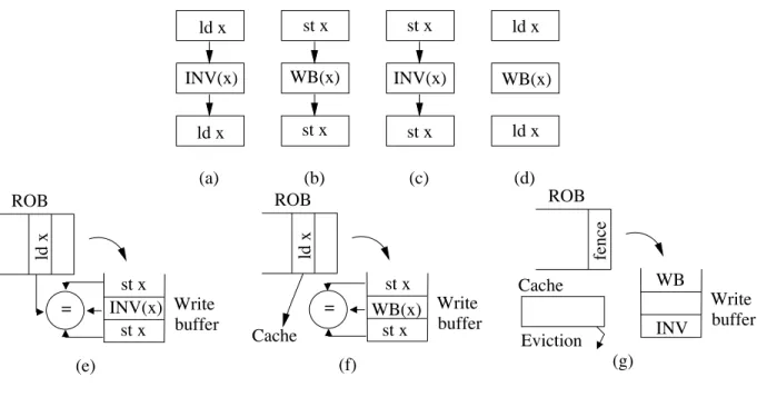
The INV and WB instructions introduce some reordering constraints with respect to loads and stores tothe same address. The important constraints are INV versus load, and WB versus store. The minimum set of ordering constraints is INV→load and store→WB. Reordering of these two sequences results in reading stale value or not exposing modified value. Thus, they must not be reordered in any case. We consider more ordering constraints to respect programmers’ intention.
Consider INV first. Neither loads that precede an INV nor loads that follow the INV can be reordered by the compiler or hardware relative to the INV (Figure 2.2a). Effectively, a thread usesINV(x)to refresh its view ofxand, therefore, reordering would imply that a load sees a different view than the one the program intended.
Consider now a WB. Neither stores that precede the WB nor stores that follow the WB can be reordered by the compiler or hardware relative to the WB (Figure 2.2b). The reason is that aWB(x)posts the value of
(b) (c) (d) (a) ld x INV(x) ld x st x st x st x st x ld x WB(x) ld x WB(x) INV(x) = = (b) (c) (d) (a) ld x INV(x) ld x st x INV(x) st x st x WB(x) st x ld x WB(x) ld x ROB ld x st x st x Write buffer WB(x) (f) Cache ROB Write buffer fence WB INV Cache Eviction (g) ROB ld x Write buffer (e) st x INV(x) st x
Figure 2.2: Ordering constraints.
xglobally and, therefore, reordering would imply that the value posted would be different than the one the program intended.
Reordering stores that precede or follow INV is also disallowed. An INV always writes-back dirty data before invalidating the line. Consequently, no data is lost. However, it also means that a reorder can affect the time when a value is posted globally, and the value posted, as in the WB case. Consequently, we disallow such reordering as well (Figure 2.2c).
Finally, loads that precede or follow a WB can always be reordered (Figure 2.2d). This is because a WB does not change the value of the line in the local cache. Hence, a reodered load sees the same value. Note that this ability to pick a load that follows a WB to the same address and execute it before the WB can help performance.
These reordering requirements can be easily enforced in hardware. INV moves in the pipeline like a store. Consequently, by the time anINV(x)in the write buffer initiates its cache update, prior loads toxwill be retired and prior stores toxwill be completed. Moreover, no subsequent load or store toxwill be allowed to initiate its cache access for as long asINV(x)is in the write buffer (Figure 2.2e).
WB is also placed in the write buffer like a write. Stores toxbefore and afterWB(x)will follow program order. Loads toxthat followWB(x)will be allowed to proceed to the cache earlier (Figure 2.2f).
because only then can a fence instruction following the WB or INV instruction complete (Figure 2.2g). On the surface, an INV completes when the L1 cache acknowledges that the line has been invalidated, and a WB when the L1 confirms that the line has been safely written back to L2. In reality, however, we need to be more conservative and wait for any current cache eviction to be completed before claiming that the WB or INV has completed. The reason is that, if the line that the WB or INV is supposed to write back or invalidate, respectively, was dirty and is currently being evicted to L2, the WB or INV instruction will not find it in L1, and we will claim WB or INV completion. However, the intended operation is not completed until the L2 is updated. Consequently, at any time, we keep a counter of the lines that are currently being written back. A fence after a WB or INV will only complete when the WB or INV are complete and the eviction counter is zero.
2.1.4 Synchronization
Since conventional implementations of synchronization primitives rely on the cache coherence protocol, they cannot be used in machines with incoherent cache hierarchies. Any lock release would have to be followed by a WB, and spinning for a lock acquire would require continuous cache misses because each read would be preceded by INV.
To avoid such spinning over the network, machines without hardware cache coherence such as the Tera MTA, IBM RP3, or Cedar, have provided special hardware synchronization in the memory subsystem. Such hardware often queues the synchronization requests coming from the cores, and responds to the requester only when the requester is finally the owner of the lock, the barrier is complete, or the flag condition is set. All synchronization requests are uncacheable. The actual support in Runnemede [14] is not published, but it may follow these lines.
In this paper, we place the synchronization hardware in the controller of the shared caches. We pro-vide three synchronization primitives: barriers, locks, and conditions. When a synchronization variable is declared, the L2 cache controller allocates an entry in a synchronization table and some storage in the controller’s local memory. When a processor issues a barrier request, the controller intercepts it, and only responds when the barrier is complete. Similarly, for a lock acquire request or a condition flag check, the controller intercepts the requests and only responds when it is the requester’s turn to have the lock, or when the condition is true. In addition, the controller releases the synchronization when timeout occurs to avoid a
Barrier Barrier
Barrier EpochsSet of EpochsSet of
EpochsSet of EpochsSet of (a) (b) (c) (d) Barrier INV INV Lock Lock Unlock Unlock WB WB Barrier WB Flag set Flag wait INV Barrier Lock Unlock Lock Unlock WB WB INV INV WB INV Epoch Epoch Epoch Epoch Epoch Epoch Epoch Epoch Epoch Epoch Epoch Epoch
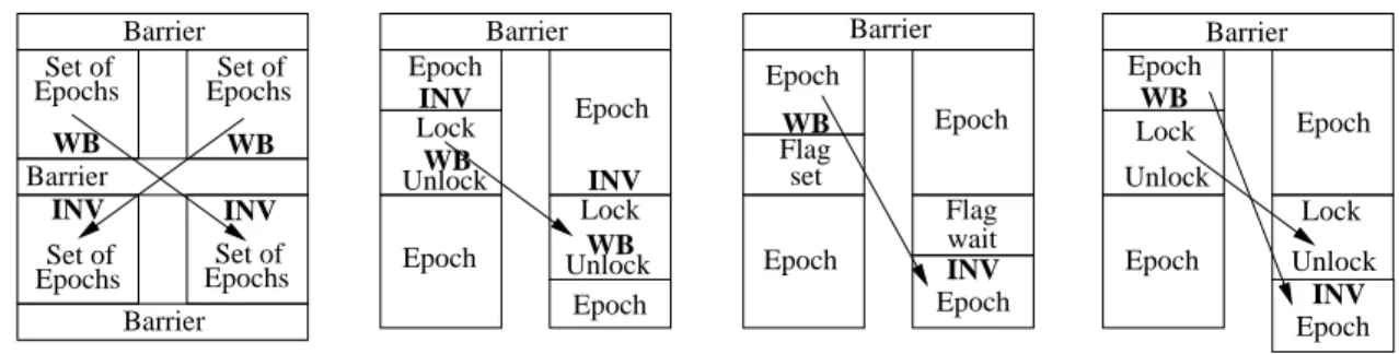
Figure 2.3: Annotations for communication patterns enabled by: barriers (a), critical sections (b), flags (c), and dynamic happens-before epoch orderings (d).
hardware deadlock.
Since synchronization support is not the focus of this paper, we do not consider further details.
2.2
Programming Model 1: MPI + Shared Intra Block
The first programming model that we propose for this machine is to use a shared-memory model inside each block and MPI across blocks. In this case, theMPI SendandMPI Recvcalls can be implemented cheaply. A sender and a receiver communicate message information using hardware synchronization through the last level cache. This eliminates receiver’s busy-waiting with spinning over on-chip network and enables a rendezvous protocol between the sender and the receiver. Data transfer is done through common shared level cache, i.e. L3 cache. Specifically, anMPI Sendof variablexis translated into a copy ofxto a location x buffin an on-chip L2-uncacheable shared buffer. AnMPI Recvof variableyis translated into a copy from locationy buffin the L2-uncacheable shared buffer to locationy. Moreover, in communication with multiple recipients such as a broadcast, there is no need to make multiple copies; a single copy tox buffsuffices. The multiple receivers will all read from the same location. Finally, we can implement non-blockingMPI Isend andMPI Irecvcalls by using another thread in the core to perform the copies. One can implement a protocol in a similar way to [26].
In the rest of this section, we focus on intra-block shared-memory programming. We first describe the proposed approach and then some advanced hardware support.
2.2.1 Intra-block Programming
Ideally, we would like to use the compiler to analyze the program and automatically augment it with WB and INV instructions. For many programs, however, it is hard to get efficient compiler-generated instrumentation due to intensive use of pointers and dynamic communication patterns. For this reason, we develop a simple approach that is easily automatable, even if it does not attain optimal performance. Also, the programmer can use his knowledge of the program to improve its performance.
The approach is based on relying on the synchronization operations in the data-race-free (DRF) program. In the DRF program, the synchronization can be used as explicit markers of changes in communication patterns. Hence, at the point immediately before and after a synchronization operation, depending on the type of synchronization, WB and INV instructions are inserted. Our algorithm decides which instructions to add, and the programmer can refine or overwrite them. For the programs with data races, we consider them separately. While the behavior of C or C++ programs with data races is undefined, it is desirable to have a way to support them as programmers originally intended. We provide fine-grained WB/INV for handling such a case.
Recall that a block has a per-core private L1 cache and a shared L2 cache (Figure 2.4a). In addition, there is a one-to-one thread-to-core mapping and no thread migration for simplicity of discussion.
L1 Proc. Block Network L2 (a) Block L3 (b) Unit Unit Network Block
Figure 2.4: Single block (a) and multi-block (b) cache hierarchy.
Annotating Different Communication Patterns.
Each type of synchronization operation gives us a clue of the type of potential communication pattern that it manages. For instance, a program-wide barrier synchronization marks a point where a thread’s post-barrier accesses can communicate with pre-post-barrier accesses from any of the other threads (Figure 2.3a).
Hence, the simplest scheme is as follows: immediately before the barrier, we place a WB for all the shared variables written since the last global barrier; immediately after the barrier, we place an INV for all the shared variables that will receive exposed reads (i.e., a read before any write) until the next global barrier.
In some cases, a thread owns part of the shared space, and reuses it across the barriers as if it was its private data. In this case, we do not need to write back and invalidate that part of the shared space. Also, the programmer can often provide information to reduce WB and INV operations. Finally, if the code between global barriers is long and we lack information on the sharing patterns, we use WB ALL and INV ALL, which write back and invalidate the entire L1 cache.
Threads often communicate by accessing variables inside a critical section protected by lock acquire and lock release (Figure 2.3b). In this case, immediately before the acquire, we place an INV for all the shared variables that will receive exposed reads inside the critical section. Moreover, immediately before the release, we place a WB for all the shared variables written inside the critical section. This basically conforms release consistency memory model. Note that we place the INVbeforethe acquire rather than afterto reduce the duration of the critical section.
Threads also coordinate with flag set-wait synchronization (Figure 2.3c). In this case, immediately before the signal, the producer thread needs a WB for all the shared variables written in the epochs since a global barrier or an equivalent point of full WB. Also, immediately after the wait, the consumer thread needs an INV for all the shared variables that will receive exposed reads in the epochs until the next global barrier or equivalent point of full INV. Like in the case of barriers, if such epochs are very long, we use WB ALL and INV ALL, respectively.
For other types of structured synchronization patterns that we have not seen in our applications, we can follow a similar methodology. However, there is also a general pattern of communication through dynamically-determined happens-before order — especially in irregular applications. After a thread com-pletes a critical section, it may want to consume data that was generated by earlier holders of the critical section before they executed the critical section (Figure 2.3d). For example, this is observed with task-queue operations. A thread places a task in the task-queue and then another thread fetches the task and processes it. The task-queue is updated using a critical section, but there is significant communication outside the critical section as the consumer processes the task.
states that there is no OCC, our programming model has to assume that there is. Hence, before a lock acquire, we add a WB of the shared variables written since a global barrier or point of full WB. After a lock release, we add an INV of all the exposed reads until the next global barrier or point of full INV. Often, these become WB ALL and INV ALL.
Discussion.
Many programs running on a Runnemede-style chip are likely to have a structure based on global barriers. In this case, it is easy for the compiler or programmer to insert WB and INV instructions.
Relying on explicit synchronization to orchestrate data transfers is insufficient when the program has data races. Indeed, the communication that data races induce in cache-coherent hierarchies is invisible in an incoherent cache hierarchy. Consider an example in Figure 2.5 with declaration of volatile variables and proper fence for memory models. Two processors try to communicate with a plain write and a spinloop without synchronization, but the spinloop may last forever (Figure 2.5a). This is because the consumer may not see the update.
for (; ; ) { if (flag) process (data); } // producer // consumer data = 1; flag = 1; (a) // consumer for (; ; ) { process (data); } } if (flag) { (b) // producer data = 1; flag = 1; fence; fence; WB (data); WB (flag); INV (flag); INV (data);
Figure 2.5: Enforcing data-race communication.
If we want to support the data-race communication, we need to identify the data race and augment it with WB, INV, and fence instructions. Specifically, as shown in Figure 2.5b, the producer needs to follow each update with a WB, while the consumer needs to precede each read with an INV. Moreover, to prevent access reordering, we need a fence between the two WBs in the producer and the two INVs in the consumer. The data-race communication pattern can be re-written by the programmer to use a hardware synchro-nization flag. In this case, the busy-waiting loop is changed to a hardware flag wait, while the producer write is changed to a hardware flag set.
Table 2.1: Classification of the benchmarks based on the communication patterns present. Benchmark Class Barrier Critical Outside Critical Data Race
FFT Barrier x
LU Barrier x
Cholesky Outside Critical x x x x
Barnes Barrier + Outside Critical x x x
Raytrace Critical x x x
Volrend Barrier + Outside Critical x x x Ocean Barrier + Critical x x
Water Barrier + Critical x x
Application Classification.
Table 2.1 lists the applications that we use for intra-block programming in Section 2.6, and classifies them according to the communication patterns present. For each application, we list the main pattern under the Maincolumn, and then other patterns that the application exhibits underOther. The patterns are those just described: barrier, critical section, flag, outside critical section, and data race.
From the table, we see that different applications have different dominant communication patterns. FFT and LU have mostly communication patterns enabled by barriers; Raytrace have patterns enabled by critical sections; Cholesky has the outside critical-section communication pattern. In addition, some applications have multiple patterns. Raytrace has asymmetric data races in its work pool structure. While a thread updates the work pool in a critical section, another thread reads it outside of any critical section. Overall, the data shows that our programming model needs to support at least all the communication patterns that we described earlier.
2.2.2 Advanced Hardware Support
Surrounding epochs with full cache invalidation (INV ALL) and writeback (WB ALL) results in unnecessar-ily low performance — especially for short epochs such as critical sections. One alternative is to explicitly list the variables or address ranges that need to be invalidated or written back. However, this approach is un-desirable because it requires programming effort and programmers are prone to make mistakes. To improve both performance and programmability, we proposed two small hardware buffers calledEntry Buffers. They can substantially reduce the cost of WB and INV in relatively-short epochs.
Modified Entry Buffer (MEB) for WB.
The MEB is a small hardware buffer that automatically accumulates the IDs of the cache lines that are being written in the epoch. Therefore, at the end of the epoch, when we need to write back the lines written in the epoch, we can use the MEB information. With this support, we avoid a traversal of the cache tags and the costly writeback of all the dirty lines currently in the cache. In short epochs, the MEB can save substantial overhead.
The MEB is designed to be cheap. It is small (e.g., 16 entries) and each entry only includes the ID of a line, rather than a line address. For example, for a 32-Kbyte cache with 64-byte lines, the ID is 9 bits. The MEB is updated in parallel with a write to the L1 cache. Specifically, every time that a clean byte is updated (recall that the cache has per-byte D bits), if the line’s ID is not in the MEB, it is inserted.
Some entries in the MEB may become stale. This occurs when an MEB entry is created for a line that is written to, and later the line is evicted from the cache by another line that is never written to. To simplify the MEB design, stale entries are not removed. At the end of the epoch, as the MEB is traversed, only dirty lines are written back.
We use the MEB in small critical sections that conclude with WB ALL because the programmer did not provide additional information. The MEB records all the lines written in the critical section. When we reach WB ALL at the end of the epoch, the MEB is used, potentially saving many writebacks. However, if the MEB overflows during critical section execution, the WB ALL executes normally.
Invalidated Entry Buffer (IEB) for INV.
At the beginning of an epoch, we need to invalidate all the lines that the epoch will expose-read and that are currently stale in the local cache. Since explicitly listing such lines may be difficult, programmers may use INV ALL. This operation is very wasteful, especially in small epochs. Hence, we propose not to invalidate any addresses on entry, and to use the IEB instead.
The IEB is a small hardware buffer that automatically collects the addresses of memory lines thatdo not need to be invalidated on a future read. They do not need to because they have already been read earlier in the epoch and, at that point, they have been invalidated if they were in the cache. Hence, they are not stale. With the IEB, we can keep the number invalidations to a very small number.
the actual address of a line that needs no invalidation on a future read. The IEB contains exact information, and is updated as follows. The IEB is accessed at every L1 read. If the line’s address is already in the IEB, no action is taken. Otherwise, the action depends on the outcome of the cache access. Specifically, if the read hits in the cache and the target byte is dirty, no action is taken. This is because the byte was written in the past by the current core and, therefore, it is not stale. In all other cases, the line’s address is added to the IEB. Moreover, if the read hits in the cache, the line is invalidated. Finally, in either hit or miss, the read gets a fresh copy of the line from the shared cache.
Unlike the MEB, the IEB does not store unneeded entries. Every read is checked against the IEB, to avoid invalidating the same line twice. Invalidations are expensive because they are followed by a cache miss in the critical path.
Finally, the IEB is most useful in short epochs like small critical sections. The reason is that if the IEB needs to track many lines, it may overflow. Each time that an IEB entry is evicted, if the corresponding line is accessed again, the hardware causes one unnecessary invalidation. The execution is still correct, but the performance decreases.
2.3
Programming Model 2: Shared Inter Block
The second programming model that we propose for this machine is to use a shared-memory model across all processors — irrespective of whether they are in the same block or in different ones (Figure 2.4b). Our main idea is that, to obtain performance, we need to have level-adaptiveWB and INV instructions. This means that, if two threads that communicate end-up being mapped into the same block, then the WB and INV operate as described until now: WB writes the line back to L2 and INV invalidates the line from L1. However, if the two threads end-up being mapped into different blocks, then WB writes back the line all the way to L3, and INV invalidates the line from both L1 and L2. We require that an application annotated with level-adaptive WB and INV runs correctly both within a block and across blocks without any modification. For completeness, we also provide an instruction that explicitly writes back lines to the L3 cache (and to the L2 in the process) and one that explicitly invalidates lines from the L2 cache (and from the L1 in the process). They areWB L3(Addr)andINV L2(Addr), respectively.
2.3.1 Inter-block Programming
In the programming approach of Section 2.2, relatively little information was needed to insert WB and INV instructions. In the approach presented here, we need two types of information to insert level-adaptive WB and INV. First, we need to know how the program’s computation is partitioned and mapped into threads. We assume static mapping of computation to threads. For example, given a parallel loop, the relevant infor-mation may be that the iterations are logically grouped intoNconsecutive chunks (whereNis the number of threads), and chunkiis executed by threadi. Note that we do not know how the threads themselves will map to physical processors at runtime (i.e., which processors and in what clusters). However, such mapping will not be allowed to change dynamically.
The second piece of information needed is the producer-consumer patterns. Specifically, we need to identify: (i) all the data that is produced by threadiand consumed by threadj, and (ii) what epochs iniand jproduce and consume the data, respectively.
Once we know this information, we can annotate the code with the level-adaptive WB and INV instruc-tionsWB CONS (Addr, ConsID)andINV PROD (Addr, ProdID). In these instructions, we augment the WB mnemonic withCONSfor consumer, and give it as a second argument the ID of the consumer thread Con-sID. Similarly, we augment the INV mnemonic withPRODfor producer, and give it the ID of the producer threadProdID.
For the example of threadsiandjproducing and consumingx, the instructions inserted are as follows (Figure 2.6). At the end of the epoch that producesx in threadi, we place WB CONS (x, j), while at the beginning of the epoch that consumesxin threadj, we placeINV PROD (x, i). The implementation of these instructions is described in Section 2.3.2.
Thread i Thread j Epoch WB_CONS(x,j) INV_PROD(x,i) Epoch = x x =
Figure 2.6: Example of level-adaptive WB and INV.
Generating this information requires deeper code analysis than in the first programming model (Sec-tion 2.2). Hence, while the first programming model can handle applica(Sec-tions with pointers and irregular
structures, this second model is targeted to more compiler-analyzable codes. In our experiments of Sec-tion 2.6, we use OpenMP applicaSec-tions.
To be able to insert level-adaptive WB and INV instructions, the compiler starts by performing inter-procedural control flow analysis to generate an interinter-procedural control flow graph of the program. Then, knowing how the computation is partitioned into threads, the compiler performs data flow analysis to find pairs of producer and consumer epochs in different threads (i,j). Then, the compiler insertsWB CONSini andINV PRODinj.
In the following, we present some details of our compiler algorithm for level-adaptive WB and INV. First, we present the general case; then we consider irregular applications.
Extracting Producer-Consumer Pairs.
Programs that have no pointer manipulation or aliasing, use OpenMP work-sharing constructs, and schedule OpenMPforloops statically are typically amenable to compiler analysis. In these programs, there may be data dependence between serial and parallel sections and between parallel sections. Typically, the relation between serial and parallel sections is relatively easy to analyze, while the relation between parallel sections is harder to analyze. It requires understanding the program’s inter-procedural control flow and performing dataflow analysis.
Inter-procedural control flow analysis finds parallelforloop iterations that potentially communicate with each other. From each startingforloop, we traverse the control flow graph to find reachableforloops. Those forloops that are unreachable are not considered further. The reachable loops are now targets of dataflow analysis. We apply DEF-USE analysis from a precedingforloop as a producer to any reachableforloop as a consumer. We compare the array structures accessed by the producer and consumer loops to determine if any is in both loops. If an array is in both, we compare the indices. Since we use static scheduling, we know the mapping of iteration to thread ID. Consequently, the compiler can determine if there is a data dependence between two threads. In this case, it puts WB CONS (address,consumerID) in the producer and INV PROD (address, producerID) in the consumer.
We perform this analysis in a semi-automatic way using some extensions to the ROSE compiler in-frastructure [43] that we developed. The analyzer gives two types of information: what OpenMP code section has producer-consumer relation, and whether this requires WB CONS/INV PROD. Programmers
insert WB/INV at proper places according to the information. Note that the consumer and producer IDs in the WB CONS and INV PROD instrumentation are typically expressed as equations of local thread ID.
Our approach is similar to interprocedural analysis used in auto parallelizing compiler [11, 28]. Our approach is also similar to the translation from OpenMP to MPI [8, 9] and to the implementation of software DSM [5]. They all use control flow and data flow analysis to find communicating data and producer-consumer pairs. In particular, inferringMPI Sendcorresponds to inserting WB CONS, and inferring MPI Recvcorresponds to inserting INV PROD.
However, our approach differs from previous techniques in four aspects. First, our approach does not maintain explicit replicated copies of data, while translated MPI code or software DSM does. Second, our approach executes the serial section in only one thread, and the result is written back by WB to the global cache; translated MPI code executes the serial section in all nodes. Third, our approach implements single producer-multiple consumers with a single WB in the producer; MPI requires multipleMPI Sendif point-to-point communication is used. Finally, our approach is reasonably efficient even if exact dataflow analysis is not possible — e.g., when we do not know the exact consumers accurately. In this case, the producer writes back the data to the last level cache. In an MPI translation, we would need to send messages to all the possible receivers.
Handling Irregular Cases.
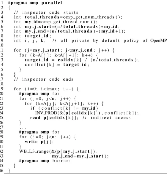
Many scientific applications use sparse computations that both are iterative and have data access patterns that remain the same across iterations. An example is the conjugate gradient method for solving systems of linear equations using sparse matrix-vector multiplications. For such codes, we use an inspector [21, 53] to gather information on irregular data accesses so that WB and INV instructions can be performed only where necessary. The inspector is inserted in the code and is executed in parallel by the threads. The cost of the inspector is amortized by the ensuing selective WB and INV.
Figure 2.7 shows an excerpt from conjugate gradient. The original code contained a loop that reads arrayp[] with indirect accesses (Line 19), and another loop that writesp[] (Line 27). We assume static scheduling of OpenMP loops with chunk distribution. Thus, continuous iterations are allocated for each thread.
1 #pragma omp p a r a l l e l 2 { 3 / / i n s p e c t o r c o d e s t a r t s 4 i n t t o t a l t h r e a d s= o m p g e t n u m t h r e a d s ( ) ; 5 i n t my id= o m p g e t t h r e a d n u m ( ) ; 6 i n t m y j s t a r t= ( n /t o t a l t h r e a d s) *my id; 7 i n t m y j e n d= ( n /t o t a l t h r e a d s) * (my id+ 1 ) ; 8 i n t t a r g e t i d; 9 i n t i , j , k ; / / a l l p r i v a t e by d e f a u l t p o l i c y o f OpenMP 10 11 f o r ( j =m y j s t a r t; j<m y j e n d; j ++) { 12 f o r ( k=A[ j ] ; k<A[ j + 1 ] ; k ++) { 13 t a r g e t i d = c o l i d x[ k ] / ( n /t o t a l t h r e a d s) ; 14 c o n f l i c t [ k ] = t a r g e t i d; 15 } 16 } 17 / / i n s p e c t o r c o d e e n d s 18 19 f o r ( i = 0 ; i<imax ; i ++) { 20 #pragma omp f o r 21 f o r ( j = 0 ; j<n ; j ++) { 22 f o r ( k=A[ j ] ; k<A[ j + 1 ] ; k ++) { 23 i f ( c o n f l i c t [ k ] ! = my id) 24 INV PROD(&(p[c o l i d x[ k ] ] ) , c o n f l i c t [ k ] ) ; 25 r e a d p[c o l i d x[ k ] ] ; / / i n d i r e c t a c c e s s 26 } 27 . . . 28 #pragma omp f o r 29 f o r ( j = 0 ; j<n ; j ++) { 30 w r i t e p[ j ] ; 31 } 32 WB L3 range ( &(p[m y j s t a r t] ) , 33 my j end−m y j s t a r t) ; 34 #pragma omp b a r r i e r 35 } 36 }
Figure 2.7: An iterative loop with irregular data references with the inspector.
produce the value obtained by each read. The result is stored in arrayconflict. Then, at every iteration of the loop that reads, it checks the ID of the writer (Line 21). If it is not the same as the reader’s ID (Line 21), it inserts an INV PROD instruction with the ID of the thread that will produce it (Line 22). Otherwise, it skips the INV.
In the figure, after the loop that writes top[], we place a WB to the L3 cache for the whole range written. We could perform a similar analysis like the one described for the read, and save some writes to L3 by using WB CONS. For simplicity, we write everything to L3.
2.3.2 Hardware Support
We implement WB CONS and INV PROD as follows. In each block, the L2 cache controller has a ThreadMaptable with the list of the IDs of the threads that have been mapped to run on this block. This table is filled by the runtime system when the threads are spawned and assigned to processors, typically at the beginning of the program.
When a thread executes theWB CONS(addr,ConsID)instruction, the hardware checks theThreadMap in the local L2 controller and determines whether or not the thread with IDConsIDis running in the same block. If it is, for each of the lines inaddr, the hardware writes back the dirty bytes only to L2. Otherwise, the dirty bytes are written back to both L2 and L3. Note that, for a given line, this operation may require checking both the L1 and L2 tags.
When a thread executes theINV PROD(addr,ProdID)instruction, the hardware checks theThreadMap in the local L2 controller and determines whether or not the thread with IDProdIDis running in the same block. If it is, for each of the lines inaddr, the hardware invalidates the line only from L1. Otherwise, the line is invalidated from both L1 and L2. For each line, this operation requires checking both the L1 and L2 tags.
Note that when a thread’s WB CONS propagates the target updates to L3, the other L1 caches in the same block, and the L1 and L2 caches in other blocks, may retain stale copies of the line. Similarly, when a thread’s INV PROD self-invalidates the target addresses from the L1 and L2 caches, the other L1s in the same block, and the L1 and L2 caches in other blocks, may keep stale values.
It is sometimes necessary for an epoch to perform a full WB or INV of the whole cache. Hence, we also support WB CONS ALL (ConsID) and INV PROD ALL (ProdID). When the producer and consumer are in different blocks, the first instruction writes back not just the local L1 but also the whole local block’s L2 to the L3. Similarly, the INV PROD ALL instruction self-invalidates not only the local L1 but also the whole local block’s L2.
A program annotated with WB CONS and INV PROD runs correctly both within a block and across blocks without modification.
2.4
Compiler Support
This work was done in collaboration with Sanket Tavarageri from Ohio State University. We present the details in the Appendix.
2.5
Experimental Setup
Since this thesis is about shared-memory programming, we evaluate the first programming model (Sec-tion 2.2) by running programs within a block, without any MPI component. We evaluate the second pro-gramming model (Section 2.3) by running programs across blocks.
Consider the intra-block runs first. We evaluate the configurations in the upper part of Table 2.2. For programming simplicity, the baseline uses WB ALL and INV ALL for all the synchronization primitives discussed in Section 2.2.1 and shown in Figure 2.3. Then, inB+M, B+I, and B+M+I, we augment the baseline with the MEB, IEB, and both MEB and IEB, respectively. These hardware buffers are only used in critical sections, which are small. Finally, we compare to the same machine with hardware cache coherence (HCC).
Intra-Block Experiments Name Configuration
Base Baseline: WB ALL and INV ALL B+M Base plus MEB
B+I Base plus IEB
B+M+I Base plus MEB and IEB
HCC Hardware cache coherence Inter-Block Experiments Name Configuration
Base Baseline: WB ALL and INV ALL to L3 Addr WB and INV of addresses to L3
Addr+L WB CONS and INV PROD
Table 2.2: Configurations evaluated.
We run the SPLASH2 applications, which use pointers heavily and have many types of synchronization. Specifically, we run FFT (64K points), LU (512x512 array, both contiguous and non-contiguous), Cholesky (tk15.O), Barnes (16K particles), Raytrace (teapot), Volrend (head), Ocean (258x258, both contiguous and non-contiguous), and Water (512 molecules, both nsquared and spatial). We use the SESC cycle-level execution-driven simulator to model the architecture in the upper part of Table 2.2. The architecture has 16
cores in a block. The coherent machine we compare to (HCC) uses a full-mapped directory-based MESI protocol.
Intra-Block Experiments Architecture 16 out-of-order 4-issue cores
ROB 176 entries
Private L1 32KB WB, 4-way, 2-cycle RT, 64B lines Shared L2 2MB WB, 8-way/bank,
11-cycle RT (local bank), 64B lines On-chip net 2D-mesh, 4 cycles/hop, 128-bit links Off-chip mem Connected to each chip corner, 150-cycle RT
Inter-Block Experiments Architecture 4 blocks of 8 cores each Shared L3 16MB WB, 8-way/bank,
20-cycle RT (local bank), 64B lines
Table 2.3: Architecture modeled. RT means round trip.
We now consider the inter-block runs. We evaluate the configurations in the lower part of Table 2.2. The baseline is a simple design that communicates via the L3 cache. This means that a WB pushes the dirty lines to both L2 and L3, and an INV invalidates the lines in both L1 and L2. Moreover, it always uses WB ALL and INV ALL. The more optimizedAddrconfiguration communicates via L3 but specifies the target addresses in the WB and INV. Finally,Addr+Luses our level-adaptive WB and INV instructions, which also specify the target addresses.
We run four OpenMP applications, namely EP, IS and CG from the NAS Parallel Benchmark suite, and a 2D Jacobi benchmark that we developed. CG is irregular. We use an analysis tool that we developed based on the ROSE compiler [43, 38] to instrument the codes with WB CONS and INV PROD instructions. We do not apply nested parallelism but, instead, only parallelize the outermost loop in a nest across all processors. We do not apply any loop optimization such as loop interchange or loop collapse either.
The architecture modeled is shown in the lower part of Table 2.2. We model 4 blocks of 8 cores each. The parameters not listed are the same as in the intra-block experiments.
2.5.1 Area analysis
An incoherent cache hierarchy requires less area that a hardware-coherent one, even if we neglect the co-herence controller logic. Specifically, consider the incoherent hierarchy first. While we explained per-byte dirty bits for the finest granularity in previous sections, it is more practical to use per-word dirty bits for
many parallel programs, which have word or coarser granularity for inter-thread communication. We as-sume per-word dirty bits in the evaluation. The lines in the L1 and L2 caches need a single valid bit plus per-word dirty bits; the lines in the last level (L3) cache only need a valid and a dirty bit. Consider now a MESI protocol, which has 4 stable line states and many transient ones. It easily needs 4 bits to encode a state. Hence, each line in the L1, L2 and L3 caches needs 4 bits for the state. In addition, each line in the L2 and L3 caches needs directory information. For example, if we consider a full-mapped directory for the hierarchy in the inter-block experiments, each L2 line needs 8 presence bits (since we have 8 processors per block), and each L3 line needs 4 presence bits (since we have 4 blocks). Overall, the MESI protocol needs more area because it requires more bits in the L3 cache, which is the largest one, while the incoherent cache hierarchy adds the overhead mostly to the smaller L1 and L2 caches.
For a cache hierarchy with 4 blocks, we find that a full-map hardware-coherent cache hierarchy has an overhead of 3.65 Mb, while the incoherent one has an overhead of only 2.96 Mb, which is 18.9% less. With more blocks, the incoherent hierarchy has more scalability because it has a constant cost regardless of the number of blocks; the hardware-coherent one requires more area for the directory as we add more blocks. For example, with 8 blocks and 8 cores per block, the hardware-coherent hierarchy has an overhead of 9.34Mb, while the incoherent one has an overhead of 5.92Mb, which is 36.6% less.
2.6
Evaluation
This section evaluates our proposed hardware support and programming models for an incoherent hierar-chical cache hierarchy like the one in Runnemede [14]. The evaluation has two parts. In Section 2.6.1, we evaluate our intra-block hardware and programming model. We compare the performance to that of the same multicore with hardware cache coherence.
In Section 2.6.2, we evaluate our inter-block hardware and programming model. For this case, there is no standard hierarchical hardware cache coherence that we can compare to. We would have to design one such protocol, explain it and justify it. Therefore, instead, we focus on evaluating the effect of our level-adaptive WB and INV instructions. Hence, we compare the performance to systems with WB and INV that always communicate via the last-level cache.
0.6 0.7 0.8 0.9 1 1.1 1.2 1.3 1.4 HCC Base B+M B + I B + M+ I HCC Bas e B + M B+I B + M+ I HCC Bas e B + M B+I B + M+ I HC C Bas e B + M B+I B + M+ I HC C Bas e B + M B+I B + M+ I HC C Ba se B + M B+I B + M+ I HCC Base B+M B + I B + M+ I HCC Base B+M B + I B + M+ I HCC Base B+M B + I B + M+ I HCC Base B+M B + I B + M+ I HCC Bas e B + M B+I B + M+ I HC C Bas e B + M B+I B + M+ I
FFT LU cont LU non-cont CHOLESKY BARNES RAYTRACE VOLREND OCEAN cont OCEAN non-cont WATER-NSQUARED WATER-SPATIAL AVERAGE INV stall WB stall Lock stall Barrier stall Execution
Figure 2.8: Normalized execution time of the applications.
2.6.1 Performance of Intra-block Executions
Figure 2.8 shows the execution time of the applications for the different architectures considered. From left to right, the bars correspond toHCC,Base, B+M,B+I, andB+M+I. For a given application, the bars are normalized toHCC. Each bar is broken down into 5 categories: stall time due to INV (INV stall) and WB (WB stall), stall time due to lock (lock stall) and barrier (barrier stall) synchronization, and rest of the execution. Barrier stall time mostly stems from load imbalance between threads. Lock stall time is the time spent waiting for lock acquires. Note any stall time for fine-grained INV/WB instruction is included in the execution time.
We classify the applications into those that exhibit coarse-grain or relatively little synchronization (FFT, LU cont, LU non-cont, and Water Spatial) and the rest. In the former class, the WB and INV overheads have very little impact. As a result, all the architectures considered have performance similar toHCC.
The rest of the applications have finer-grain synchronization. In these codes, the overhead of WB and INV stalls inBaseis often large and, in the case of Raytrace, very large. In Raytrace, where theBasebar reaches over 2, there are frequent lock accesses in a set of job queues. Its fine-grain structure is the reason for the large overhead. The bars also show that the overhead inBasecomes mostly fromINV stall,WB stall, andlock stall. The latter is largely the result ofWB stallin the critical section and its chaining effect to other acquire waiters. On average for all the applications,Base’s execution time is 20% higher thanHCC.
We can speed-up execution by using the MEB to reduce the number of WBs that are needed before exiting the critical sections. This optimization succeeds in eliminating practically all theWB stallandlock
stall. We can see, therefore, that the MEB is very effective. The resulting bars (B+M) are close toHCC. One exception is Raytrace, where the bar is still around 1.4.
The third bar (B+I) shows that the IEB alone is not very effective to speed-up execution. TheINV stall reduces a bit, but theWB stallandlock stallreturn, and the bars return to about the same height asBase. The problem is that, even though the number of INVs decreases, there is a large number of WBs before exiting the critical sections, which lengthens the critical sections and slows down the program. The fewer misses due to fewer INVs do not help significantly. Moreover, the IEB is so small that it sometimes overflows, becoming ineffective.
However, the fourth bar (B+M+I) shows that, by adding both the MEB and the IEB, we get the best performance. All the categories of overheads decrease. As a result, the programs are now not much slower than with hardware cache coherence (HCC). On average, the execution time of the applications withB+M+I is only 2% higher than withHCC. This is a large speed-up compared toBase, whose execution time was 20% higher thanHCC. Overall, we have a system without hardware cache coherence that is about as fast as one with hardware coherence.
We now consider the traffic generated byHCCandB+M+I. Given thatHCCandB+M+Ihave a similar average performance, their relative traffic is a proxy for their relative energy consumption. Figure 2.9 shows, for each application, their relative traffic in number of flits normalized toHCC. Each bar is broken down into traffic between the L2 cache and memory (memory), and three sources of traffic between the processor and L1/L2: linefill due to read/write misses, writeback traffic, and invalidations. Traffic-heavy synchronization using benign data races is converted to hardware synchronization primitives.
From the figure, we see that these applications have on average slightly less traffic inB+M+Ithan in HCC. This is despite the fact that these applications were not written for an incoherent cache hierarchy. As a result,B+M+Isuffers from the fact that the analysis of which words need to be invalidated or written back is not very precise, and often requires the use of INV ALL and WB ALL. On the other hand,B+M+Iremoves traffic overHCCin three ways. First,B+M+Icauses no invalidation traffic. Second,B+M+Idoes not suffer from ping-pong traffic due to false sharing. Finally,B+M+Iperforms writeback of only dirty words, thanks to its per-word dirty bits. Overall,B+M+Icauses only slightly less traffic and, hence, consumes about the same energy asHCC.
0.4 0.5 0.6 0.7 0.8 0.9 1 1.1 1.2 HCC B+ M +I HCC B+ M +I HCC B+ M +I H CC B+ M +I H CC B+ M +I HCC B+M +I HCC B+M +I HCC B+ M +I HCC B+ M +I HCC B+ M +I HCC B+ M +I H CC B+ M +I FFT LU cont LU non-cont
CHOLESKY BARNES RAYTRACE VOLREND OCEAN
cont OCEAN non-cont WATER-N SQUARED WATER-SPATIAL AVER-AGE
linefill
writeback
invalidation
memory
Figure 2.9: Normalized traffic of the applications.
inB+M+Iwill be lower than inHCC— because of the three reasons listed above. Moreover, even if the performance and energy is similar for HCCand B+M+I, the latter has the major advantage of needing simpler hardware, which translates into lower time-to market for the machine, and lower machine cost.
2.6.2 Performance of Inter-block Executions
To evaluate the effect of level-adaptive WB and INV, we start by counting the number of global WBs (those gone to the L3) and global INVs (those gone to the L2). Recall thatAddralways performs global WBs and INVs, whileAddr+Lonly performs them if producer and consumer are in different blocks. Figure 2.10 compares these counts forAddrandAddr+Lfor our applications. The bars are normalized to the values for Addr.
Only Jacobi and CG take advantage of level-adaptive instructions (Addr+Lbars). In Jacobi, Addr+L reduces the number of global WBs and INVs to one third of the number inAddr. This shows the impact of WB CONS and INV PROD. In CG, as explained in Section 2.3.2, we use INV PROD but not WB CONS. Hence,Addr+Lonly reduces the number of global INVs, not WBs. The number of global INVs remaining is 78% of the number inAddr. With these level-adaptive instructions, we reduce network traffic and miss
![Figure 1.1: Runnemede chip architecture from [14].](https://thumb-us.123doks.com/thumbv2/123dok_us/10225570.2926393/13.918.110.811.108.313/figure-runnemede-chip-architecture-from.webp)


![Figure 3.1: Hierarchical memory configuration (borrowed from the final report of [31]).](https://thumb-us.123doks.com/thumbv2/123dok_us/10225570.2926393/42.918.198.716.112.520/figure-hierarchical-memory-configuration-borrowed-final-report.webp)
![Figure 3.2: OCR dependency examples (borrowed from [31]).](https://thumb-us.123doks.com/thumbv2/123dok_us/10225570.2926393/43.918.188.745.116.517/figure-ocr-dependency-examples-borrowed-from.webp)
![Figure 3.3: FSim architecture model (borrowed from the final report of [31]).](https://thumb-us.123doks.com/thumbv2/123dok_us/10225570.2926393/44.918.193.722.114.531/figure-fsim-architecture-model-borrowed-final-report.webp)