Virtuo 75, Virtuo 80/2 and Virtuo 80/3
English
Store this document in a safe place
959.124.02.EN Scan this QR-Code
Content
page Introduction 4 CE declaration 4User Manual
5 1. General 52. Precautions and safety instructions 5
3. Taking the appliance in operation 6
3.1 For the first time 6
3.2 Protection 6
3.3 Projector safety mode 6
4. Remote control 7
4.1 Replacing/placing batteries 7
5. Operation via the DRU Virtuo App 7
6. Main switch 8
7. Maintenance 8
8. Cleaning the glass pane 9
9. Environment 9
9.1 General 9
9.2 The appliance 9
10. Warranty 9
3
Installation manual
10Step-by-step installation plan 10
1. Safety 12 1.1 Regulations 12 1.2 Safety instructions 12 2. Preparation 13 2.1 Unpacking 13 2.2 Electric connection 14
2.3 Switch contact connection 15
4. Installation 16
4.1 Placing the appliance 16
4.2 Placing appliance 18
4.3 Additional installation options 18
4.3.1 Platform combined with lower decorative strip 18
4.3.2 Platform adjacent to the glass 19
4.3.3 Back and side wall adjacent to the glass of the side pane 23
4.4 Placing the chimney breast 25
5. The appliance 26
5.1 Glass panes 26
5.1.1 Removing the front glass pane 26
5.1.2 Placing the glass pane 26
5.1.3 Cleaning the glass pane 27
5.2 Preparing the projector for first use 27
5.3 Wood set, chips and glow rock set 27
5.3.1 Installing the wood set 28
6. Final check 36
7. Delivery 36
7.1 Projector & Projector mirror 37
7.2 Heating element 37
7.3 Parts 37
8. Maintenance 37
Introduction
DRU, a manufacturer of gas-fired and electric stoves, develops and produces products that comply with the highest quality, performance and safety requirements. For that reason, this appliance has a CE label, which means that it complies with the essential requirements of the European directives. The appliance is supplied with a combined installation manual and user manual. Maintenance of the appliance should be performed by a professional certified specialist with proven know-how and skills. A professional specialist takes into account all technical aspects, such as heating output and electrical requirements.
The information in this user and installation manual will ensure the appliance is installed in such a way that it will function properly and safely. This manual discusses the installation of the appliance and the regulations that apply to the installation. In addition, the appliance’s technical data are shown and information is provided about maintenance, possible malfunctions that might occur and their possible causes. Fully and carefully read and use this installation manual before installing the appliance. Where the installation instructions are not clear, national/local legislation should be observed. The appliance comes with a wood set, chips and a set of glow rocks.
The flame effect of this atmospheric stove can be used with and without heating. This DRU appliance was designed to be built into a chimney breast or mantel. The following symbols are used in the manual to indicate important information:
Work to be performed. Suggestions and recommendations.⚠
You will need these instructions to prevent problems that might occur during installation and/or use.⚠
You need these instructions to prevent fire, personal injury or other serious damages.After final delivery, the manual should be handed over to the end user.
CE declaration
DRU declares that company internal measures guarantee that appliances produced by DRU meet the essential requirements and guidelines of the regulation concerning electric stoves and the accompanying standards. This declaration loses its validity if changes are made to the appliance without written permission from DRU. The instructions in the manuals must also be observed at all times. A copy of the CE test certificate can be downloaded via www.druservice.com
Product: Electric built-in decorative fire Type: Virtuo 75, Virtuo 80/2, Virtuo 80/3
Regulations: (EU) 2015/1188
Directives: 2014/35/EU, 2014/30/EU Applied harmonized standards: EN 55014-1:2017
EN 55014-2:2015 EN 61000-3-2:2014 EN 61000-3-3:2013
EN 60335-1:2012 + A11:2014+A12:2017+A13:2017+A14:2019 EN 60335-2-30:2010+A11:2012
Internal measures by the company guarantee that equipment produced complies with the requirements of the prevailing EC directives and the standards applied.
DRU Verwarming B.V. Duiven, 20-04-2020 Postbus 1021, NL-6920 BA Duiven
Ratio 8, NL-6921 RW Duiven www.drufire.com
R.P. Zantinge, Managing director
installation and user manual
5
1. General
⚠
Carefully read the user manual.⚠
Observe the precautions/instructions in this manual.2. Precautions and safety instructions
Carefully observe the following precautions and instructions:
⚠
- It is recommended to have the appliance maintained 1x per year. - Have your appliance installed and maintained by a competent installer.- It is possible for the appliance to switch on unintentionally as a result of other remote controls that do not belong to the appliance. Therefore, please take measures to prevent damage to goods or persons in such a case.
⚠
- Do not make any changes to the appliance yourself.- In case of a broken or torn glass pane, do not use the appliance and remove the plug from the socket. Contact your dealer.
- If the plug or mains cord are damaged, these should be replaced immediately. Have this done by a qualified person.
- Children should not play with the appliance.
- Cleaning and user maintenance should not be performed by children.
- The appliance was designed for atmospheric and heating purposes. This means that all visible surfaces, including the glass pane, can become hotter than 100C°. People who have poor perception of the consequences of their actions should never be alone near a heating appliance, it is also recommended to place a temporary protective grille in front of the appliance. If it is possible that vulnerable people are regularly present in the room, a fixed guard should be mounted around the appliance.
- This appliance can be used by children as of 8 years of age and persons with reduced physical, sensory or mental capacities or a lack of experience and know-how, provided they are supervised and have been instructed concerning the use of the appliance and are able to recognise the hazards involved.
- The appliance may only be operated and used when supervised. In this way the situation around the appliance and the people that are present are always supervised to be able to prevent possible hazards when switching on and using the appliance.
- Children of less than 3 years should be kept away unless continuously supervised.
- Children aged from 3 years and less than 8 years shall only switch on/off the appliance provided that it has been placed or installed in its intended normal operating position and they have been given supervision or instruction concerning use of the appliance in a safe way and understand the hazards involved. Children aged from 3 years and less than 8 years shall not plug in, regulate nor clean the appliance or perform user maintenance.
⚠
Some parts of this product can become very hot and cause burns. Particular attention has to be given where children and vulnerable people are present. If the appliance will not be used for an extended period of time, we recommend removing the plug from the socket and removing the batteries from the remote control. This will prevent damage due to leaking batteries.3. Taking the appliance in operation
3.1 For the first time
⚠
If the chimney breast is made of stone-like materials, or has been finished with plaster, it should dry for at least 6 weeks prior to taking it into operation to prevent shrinkage cracks.3.2 Protection
To prevent unsafe situations, you should carefully observe the following measures and instructions.
⚠
Make sure that combustible objects and/or materials such as curtains have a minimum distance of 50 cm from the appliance;- Do not dry clothes, towels etc. on and/or near the appliance, in order to prevent fire; - Avoid contact with hot parts of the appliance to prevent burns;
- Do not leave children and persons who cannot judge the consequences of their actions alone with a heating appliance. - Place the remote control out of reach from children and persons who cannot properly judge the consequences of their
actions.
3.3 Projector safety mode
The projector is equipped with a safety mechanism that automatically turns off after 8 hours of continuous use. When in sleep mode the projector shows no image.
If sleep mode is enabled the appliance has to be switched off for 10 seconds before it can be used again. Switching off the appliance can be done using the remote (see fig. 4-1).
38C-2666
≥200
≥500
7
4. Remote control
One of the methods of operation is the use of a wireless remote control (see fig. 4-1).
- At each operating action, the appliance provides a confirmation tone.
- When switching on the heating element at the low heating position, the appliance provides 1 confirmation tone, when switching to the high heating position, the appliance provides 2 confirmation tones.
The remote control has the following functions:
A - Check light.
B - Switching the appliance on and off from standby mode. C - Switching between heating positions.
D - Switching between the different flame pictures. E - Switching sound effects on and off.
⚠
It is possible that the appliance responds to other wireless remote controls in the house, such as those for the television or radio. Therefore, take precautions against unintended activation of the appliance.4.1 Replacing/placing batteries
The remote control works with two AAA batteries. In case of a poor operation and/or if the check light no longer responds or responds weakly when the buttons are pressed, the batteries must be replaced. This is done as follows:
Remove the cover from the back of the remote control by sliding it downwards.
Remove, if applicable, the old batteries.
Place the new batteries in the holder in the correct orientation.
Slide the cover back on the remote control until it clicks.
The remote control is ready for use.⚠
- Do not throw empty batteries away as residual waste, but dispose them as household hazardous waste. - Remove the batteries from the remote control when they will not be used for a long period of time, to prevent damage as a result of leaking batteries.5. Operation via the DRU Virtuo App
In addition to the remote control, the appliance can also be operated by means of an app on your smartphone or tablet. For more information, visit our website www.drufire.com or ask your dealer.
A B C D E 38C-26694-1
6. Main switch
The appliance is provided with a main switch on the inside of the upper decorative strip (see fig. 5-1). This main switch can be used to switch off the entire electrical system of the appliance.
⚠
- The main switch does not make the appliance fully free from voltage. - Always remove the plug from the socket prior to cleaning work.7. Maintenance
It is recommended to have the appliance checked, cleaned and, if necessary, repaired once per year by a skilled installer. It should at least be established that the appliance is working properly and safely.
⚠
- As user, you are only allowed to clean the appliance on the outside. - Do not use corrosive or abrasive detergents for cleaning.- The appliance can be cleaned with a soft cloth and, if necessary, a soft detergent. Aggressive detergents (such as chlorinated or abrasive detergents) could lead to corrosion or dull spots.
38C-2665
5-1
9
8. Cleaning the glass pane
For an optimum experience of the appliance, it is recommended to make the glass pane as clean as possible and keep it clean.
Therefore, regularly clean the glass pane(s) on the outside of the appliance.
⚠
The glass pane(s) to be cleaned should be cooled down to room temperature.⚠
- Only clean the glass pane(s) on the outside of the appliance. - Avoid damage to the glass pane(s) when cleaning. - Use a damp microfibre cloth. Other materials such as (kitchen) paper, steel wool, etc., could cause scratches. - It is recommended to use a good quality glass cleaner as a detergent for the glass panes.- We recommend wearing cotton gloves when cleaning the glass panes in order to prevent finger prints.
9. Environment
9.1 General
- Packaging materials must be disposed of in accordance with the regulations.
- Batteries are considered as household hazardous waste and should be disposed of in special containers.
9.2 The appliance
When the appliance has reached the end of its life, it should be processed in a sensible way, so that the appliance or parts of it can be used again.
Removing the appliance.
Dispose of the appliance at a recognised collection point. In case of doubt, contact your council for information about available disposal and collection systems.10. Warranty
The warranty for your DRU appliance will be provided via your supplier. In case of complaints you will be able to contact them. Your supplier will then involve DRU if he feels this is necessary. The factory warranty is valid 2 years after the date of purchase, but does not apply to damages to the paint that result from objects that have fallen and/or have been placed against the mantel of the appliance..
Step-by-step installation plan
The major steps of the installation are described below. Carefully perform these steps and tick them once they have been performed correctly.
⚠
First carefully read the manual before the appliance is installed.The correct type of appliance has been supplied (table 1-1)
❏
The appliance is free from damage
❏
All parts have been supplied (table 2-1)
❏
A 230V 50Hz socket is present within 1 metre of the appliance
❏
The plug of the appliance is within easy reach of the user after installation❏
The chimney breast meets the minimum dimensions (fig. 4-4)❏
The glass panes have been cleaned on the inside and outside (section 5.1.3)❏
The wood set, chips and glow rocks have been placed correctly (section 5.3.2)❏
The remote control has been prepared for use and works correctly (section 4 User Manual)❏
The appliance and remote control have been checked for proper operation❏
The installation has been checked in relation to operation and safety❏
The installation meets the requirements relating to fire safety❏
There are no objects within the radiation range of the appliance (fig. 2-2)❏
The total installation complies with applicable national and local building regulations❏
The user has been familiarised with the appliance (section 6)❏
11
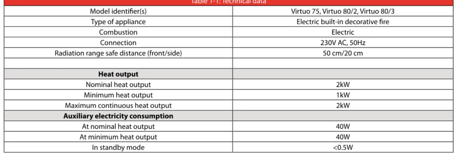
Table 1-1: Technical data
Model identifier(s) Virtuo 75, Virtuo 80/2, Virtuo 80/3 Type of appliance Electric built-in decorative fire
Combustion Electric Connection 230V AC, 50Hz Radiation range safe distance (front/side) 50 cm/20 cm
Heat output
Nominal heat output 2kW Minimum heat output 1kW Maximum continuous heat output 2kW
Auxiliary electricity consumption
At nominal heat output 40W At minimum heat output 40W In standby mode <0.5W
1. Safety
- First read the instructions before you start placing the appliance. - Observe the regulations/instructions in this manual.
- Read this manual carefully to ensure the proper and safe installation of the appliance.
- First check that the technical execution of the appliance to be installed is correct (see table 1-1). - Observe the generally applicable regulations and precautions/safety instructions in this manual. - Keep this manual with the appliance for future reference.
1.1 Regulations
Please install the appliance in accordance with the applicable national, local and constructional (installation) regulations.
1.2 Safety instructions
Ensure basic precautions to prevent the risk of electric shocks, fire and personal injury. The following precautions and safety instructions will help. Therefore observe them carefully;
⚠
- Installation and maintenance of the appliance should only be performed by a recognised and skilled installer. - After installation, the socket to which the appliance is connected should be accessible at all times.- Take into account the minimum internal dimensions of the chimney breast when installing a built-in appliance (see fig. 4-6).
- This atmospheric appliance is not suitable for use as a primary heating source.
- Do not cover the appliance and/or do not wrap it in an insulation blanket or any other material. - Do not use the appliance outdoors.
- Only use the supplied materials and place them exactly as described.
⚠
- Do not make any changes to the appliance.- Keep combustible objects and/or materials outside the appliance’s radiation range (see fig. 2-2).
- Always keep the convection opening at the front of the appliance free so that warm air is able to circulate freely. - The appliance was designed for atmospheric heating purposes. This means that all visible surfaces, including the glass
pane, can become hotter than 100°C. People who have poor perception of the consequences of their actions should never be alone near a heating appliance, it is also recommended to place a temporary protective grille in front of the appliance. If it is possible that vulnerable people are regularly present in the room, a fixed guard should be mounted around the appliance. If it is possible that vulnerable people are regularly present in the room without supervision, a fixed guard should be mounted around the appliance.
- Do not allow children or helpless people near the appliance without supervision. Also keep the remote control out of their reach.
- Children of less than 3 years should be kept away unless continuously supervised.
- Children aged from 3 years and less than 8 years shall only switch on/off the appliance provided that it has been placed or installed in its intended normal operating position and they have been given supervision or instruction concerning use of the appliance in a safe way and understand the hazards involved. Children aged from 3 years and less than 8 years shall not plug in, regulate nor clean the appliance or perform user maintenance.
⚠
Some parts of this product can become very hot and cause burns. Particular attention has to be given where children and vulnerable people are present.- Do not use this appliance in combination with external control equipment, such as timers, thermal controllers or programmed controllers, which automatically switch on the appliance.
- Do not place the appliance in a damp room or near a bath, shower or swimming pool. - Check the complete installation prior to commissioning.
- Do not use the appliance when a glass pane is broken and/or cracked, until it has been replaced.
installation manual
13
2. Preparation
2.1 Unpacking
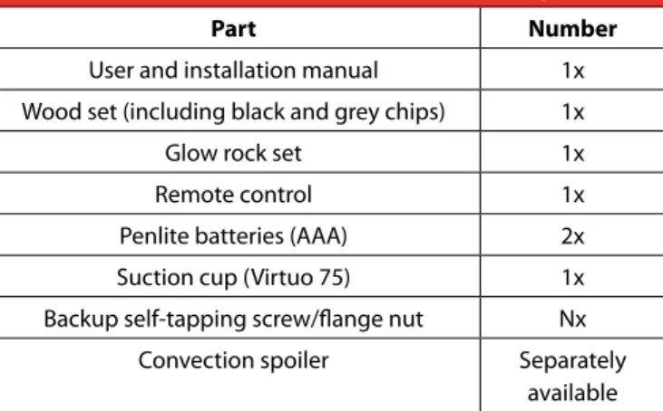
Table 2-1 indicates which components should be available after removing the packaging. Contact the supplier if you find that not all components have been supplied.
Note the following items when removing the packaging:
Remove all packaging and protective materials.
Remove all supplied components in, on and/or at the appliance.
Check the appliance and accessories for damages (during transport).
If necessary, contact your supplier.
Never install an appliance that is damaged!
Remove screws that are used to fix the appliance to the pallet.
Packaging must be disposed of by means of the applicable separation methods.⚠
Keep plastic bags away from children.⚠
Protect the projector and other electric components against (building) dust and (building) damp!Table 2-1: Parts included with the delivery
Part Number
User and installation manual 1x Wood set (including black and grey chips) 1x
Glow rock set 1x
Remote control 1x
Penlite batteries (AAA) 2x Suction cup (Virtuo 75) 1x Backup self-tapping screw/flange nut Nx
Convection spoiler Separately available
2.2 Electric connection
The appliance is provided with a tie-wrap to create a strain relief for the mains cord. This is to prevent the cord from unintentionally coming loose from the appliance. The strain relief is installed as follows:
Take the accompanying mains cord and connect it to the rear of the appliance with the three-pole plug (see fig. 2-1).
Take the provided tie-wrap and lead it through the slots intended for that purpose above the connection. (see fig. 2-1).
Attach the mains cord to the appliance with the tie-wrap and tension the tie-wrap so that the mains cord can no longer shift.
Connect the appliance to the mains by inserting the plug in the socket.⚠
After installation, the socket to which the appliance is connected should be accessible at all times.- If necessary, place a wall socket in accordance with the applicable regulations.
- In case of an installation where the plug is removed from the mains cord, the appliance should be connected by a qualified person. In case of such an adaptation, there should always be an easily accessible switch after installation, in order to be able to make the appliance fully free from voltage.
⚠
- Make sure that, in addition to the main switch on the appliance, it is easy to make the appliance free from voltage. For instance by disconnecting the plug or using a 2-pole switch placed by a recognised installer in accordance with normal regulations.0.1 - 1 M
38C-3661 2-1
15
2.3 Switch contact connection
The appliance was developed for connection to a power source of 230/240 Volt AC 50Hz. Prior to starting the installation of the appliance, check that the power source on the location corresponds with that of the appliance. Place the electrical connection free from the appliance, so that it remains accessible after installation. The wiring of the power cable was used in accordance with the following arrangement:
GREEN/YELLOW – EARTH BLUE - NEUTRAL WIRE BROWN - PHASE
⚠
The colours of the wires of the power source on the location could deviate from the colours of the wiring in the appliance. It is therefore important to take the following into account:- The green and yellow wire must be connected to the power source marked with the letter E or the earth symbol. - The blue wire must be connected to the power source marked with the letter N.
- The brown wire must be connected to the power source marked with the letter L.
⚠
The appliance should at all times be connected with an earth connection.⚠
Replace fuses only by fuses of the right size and the correct value.38C-2668
≥200
≥500
Tmax 60°C Tmax 80°C 2-24. Installation
4.1 Placing the appliance
Separate sections describe different ways of placing the appliance. The general description below for placing the appliance applies to all these sections:
⚠
Place the appliance on the location where it will be installed and take the following into account: - The construction dimensions of the appliance (see fig. 4-1, 4-2 and 4-3).- The minimum chimney breast dimensions (see section 4-4).
- There are no combustible objects or materials within the radiation range of the appliance (fig. 2-2). - Place the appliance in such a way that a fire hazardous situation can never occur.
- A stable arrangement has been achieved for the appliance to be installed.
When the appliance is placed in an existing open chimney or flue pipe, it is important that it is closed to prevent up and down air flows. Due to these air flows, the operation of the appliance can be limited.
803
510
30
17
1000
50
550
788
399
940
880
510
30
558
137
350
Virtuo 80/3
38C-2657/0 4-31000
50
550
788
399
842
872
510
30
558
137
350
Virtuo 80/2 R
38C-2658/0 4-24.2 Placing appliance
When placing the appliance, observe the following instructions:
⚠
The appliance should always be placed on the adjustable feet.
Set the height of the appliance using the adjustable feet and level the appliance.4.3 Additional installation options
The appliance can be placed with a platform. This can be done in combination with a lower decorative strip or with the platform connecting to the glass. The accompanying chimney breast can be used with or without a false wall (see fig. 4-6, 4-7 and 4-8).
It is also possible to have the interior plate of the appliance continue to the outside. The chimney breast can be placed up to the side glass pane(s) (see fig. 4-6, 4-7 and 4-8 option A + B).
4.3.1 Platform combined with lower decorative strip
Create a recess in the platform, in which the appliance will be placed. See fig. 4-6, 4-7 and 4-8 (A and C) for options and dimensions.⚠
If a false wall is used, the recess will be less deep.
Mutually adjust the height of the appliance and assembly set, so that the top side of the platform connects to the bottom side of the lower decorative strip.403 140 800 562 884 514 403 846 38C-2656 2 mm 2 mm 562 807 4-4
installation manual
19
4.3.2 Platform adjacent to the glass
Create a recess in the platform, in which the appliance will be placed. If a false wall is used, the recess will be less deep. Maximum material thickness is 30 mm. See fig. 4-6, 4-7 and 4-8 (B and D) for options and dimensions.
Lower the lower decorative strip (see fig. 4-5 step 2) by loosening the two screws by a few turns. Place the lower decorative strip at the required height and tighten the screws again.
Remove the centring ring at the bottom of the decorative strip by breaking it off at the front (see fig. 4-5 steps 2 and 3): Virtuo 75: 2x step 4Virtuo 80/2: 1x step 3, 1x step 4 Virtuo 80/3: 2x step 3
Mutually adjust the height of the appliance and assembly set, so that the bottom side of the platform connects to the adjustable profiles.⚠
- Make sure that the end of the decorative strip remains flat (see fig. 4-5 steps 2 and 3).- Do not allow the weight of the platform to rest on the appliance and/or the adjustable profile.
- Make sure there is sufficient space between the platform and the springy glass pane strip in order to be able to remove/ place the front glass pane. Use the end stops on both sides of the appliance for this.
38C-2663 2x 1 2 3 4 4-5
A
B
A
C
B
D
C
D
38C-2670 810 520 ≈ ≥ 10 ≥ 807installation manual
21
A
B
C
D
38C-2671 800 358B
D
815 405 815 520C
A
800 471 4-7825 485
A
B
C
D
798 798 825 375A
C
B
D
38C-2662installation manual
23
4.3.3 Back and side wall adjacent to the glass of the side pane
When constructing the wall up to the side pane, proceed as follows:
Make sure the back wall to be placed has the correct dimensions (see fig. 4-10 and 4-11).
Maintain a 5 mm distance between the wall and the side pane.⚠
- In case of materials up to the glass, heat-resistant material should be used that is at least able to resist temperatures of 85°C.For each appliance there are specific steps to connect the side wall to the glass. Observe the next steps that apply to the appliance to be placed.
Virtuo 75
Side wall adjacent to the glass:
Remove the vertical decorative strip on the left and right side by removing the 2 recessed-head screws and 2 self-tapping screws (see fig. 4-9 Step 1).
Screw the 2 self-tapping screws back in the appliance.
Remove the centring block at the ends of the upper and lower decorative strip by cutting into it and breaking it off (see fig. 4-9 step 5).⚠
Ensure a margin of at least 5mm between the wall and the glass pane.Virtuo 80/2
Side wall adjacent to the glass:
Remove the vertical decorative strip on the left and right side by removing the 2 recessed-head screws and 2 self-tapping screws (see fig. 4-9 Step 1).
Screw the 2 self-tapping screws back in the appliance.
Remove the centring block at the ends of the upper and lower decorative strip by cutting into it and breaking it off (see fig. 4-9 step 5).⚠
Ensure a margin of at least 5mm between the wall and the glass pane.Back wall adjacent to the glass:
Move the vertical decorative strip (see fig. 4-9 Step 4) by loosening the two bolts by a few turns. Place it at the required depth and tighten the bolts again.
Place the wall between the upper and lower decorative strip (see fig. 4-10).⚠
Ensure a margin of at least 5mm between the wall and the glass pane.Virtuo 80/3
Back wall adjacent to the glass:
Move the vertical decorative strip (see fig. 4-9 Step 4) by loosening the two bolts by a few turns. Place it at the required depth and tighten the bolts again.
Place the wall between the upper and lower decorative strip (see fig. 4-10).
Repeat the above-mentioned steps for the other side, if applicable in the configuration.550 38C-2673 2x 2x 2x 2x tooltip 1 2 3 4 5 4-9
installation manual
25
4.4 Placing the chimney breast
⚠
- The appliance should not function as a bearing element in the structure. Make sure the appliance does not have to bear the weight of the chimney breast for example.- When using stone-like materials and or plaster finishing, allow the chimneybreast to dry for at least six weeks prior to using the heater in the appliance in order to prevent cracks from appearing. During the drying period it is possible to use the appliance with the heater switched off.
When placing the chimney breast, you should take the following into account: - The minimum internal dimensions of the chimney breast (fig. 4-4).
- The dimensions of the glass pane, so that it can be placed/removed after placing the chimney breast.
- Placement of decorative strips, frames and such like; if possible, place them after the performance of any structural work. Use good quality painting tape and remove this tape after plastering or painting work.
Check the following items, before the chimney breast is fully closed:
Has no plastering work been performed on or across the edges of the construction frame? This due to the fact that cracks can occur in the plastering due to heat from the appliance.
The plastering does not hinder the placement and removal of the glass pane. 38C-2669≥ 5mm
554
5. The appliance
5.1 Glass panes
After placement of the wood set (see section 5.3), it is possible to place the glass panes:
⚠
Avoid damaging the glass panes during removal/placing.5.1.1 Removing the front glass pane
Observe the following instructions for removing the front glass pane (see fig. 5-1). Caution! Prevent the glass pane from getting damaged.
Unscrew the bolts of the glass strip on the top side and remove them together with the glass strip; In the case of the Virtuo 75, place the suction cup on the glass pane to remove it from the appliance;
Properly hold the glass pane on both sides or the suction cup;
Slightly tilt the top of the glass pane towards you;
Carefully lift up the glass pane and tilt the bottom of the glass pane towards you;
Remove the glass pane.5.1.2 Placing the glass pane
Placing the glass pane will take place in reverse order of removing the glass pane, as described above: - Do not over-tighten the bolts, as they could break or the thread could be stripped.
- Place the glass pane with the logo at the bottom right.
⚠
Make sure the front glass pane fully connects to the side pane(s) and the angle profile (no opening should be created between the side pane, front pane and angle profile).- Make sure that the groove of the glass pane strip at the bottom side is free from dirt and chips before the glass pane is placed.
1
2
4
3
5
installation manual
27
5.1.3 Cleaning the glass pane
For an optimum experience of the appliance, it is recommended to clean the glass pane.
⚠
The glass pane(s) to be cleaned should be cooled down to room temperature.⚠
Avoid damage to the glass pane(s). - Use a damp microfibre cloth. Other materials such as (kitchen) paper, steel wool, etc., could cause scratches. - It is recommended to use a good quality glass cleaner as a detergent for the glass panes.- We recommend wearing cotton gloves when cleaning the glass panes in order to prevent finger prints.
5.2 Preparing the projector for first use
When taking the projector into operation, take note of the following:
- Remove the lens cap from the projector when used for the first time (see fig. 5-2 step 1).
- If necessary, focus the projection on the 3D Screen by adjusting the focus ring on the projector (see fig. 5-2 step 2).
5.3 Wood set, chips and glow rock set
The appliance comes with a wood set, chips and a set of glow rocks. Place them exactly as described for an optimum operation of the appliance.
⚠
- In the figures, the colour is not always shown correctly.- Only use the supplied wood set, chips and glow rock set. Place them exactly as described.
1
2
38C-2685
5.3.1 Installing the wood set
The appliance is supplied with a wood set; two logs of this set and the 3D Screen have been pre-assembled (logs E and F). The remaining logs can be found in the box supplied with the appliance and must be placed on location according to the following instructions.
⚠
- When placing the wood set and other decorative materials, it is important that the receiver for the remote control does not get damaged and remains visible between the decorative materials. (see fig. 5-3)- Place the logs exactly in accordance with the following description in order to achieve a correct alignment of the flame picture and the logs.
After placing the wood set, glow rocks and chips, check the remote control for proper operation. Do this prior to placing the glass panes, as the receiver is no longer within reach afterwards. - When placing the wood set, chips and set of glow rocks, switch on the projector to achieve a correct alignment of the projection on the log set (see fig. 5-18).- In the case of the Virtuo 75 and Virtuo 80-2, it is dark in the corners behind the log set. Use a flash light, for example, to get a better view of the activities.
E
F
B
A
C
29
Step 1
Carefully remove the log set and glow rocks from their packaging. The woodset and glow stone set consist of the following parts:
- Woodset (see fig. 5-4)
- Black chips (fig. 5-5) and grey chips (see fig. 5-6) - Ashes (see fig. 5-7)
- Glow rocks (see fig. 5-8)
- Gray coals (see fig. 5-9) and black coals (see fig. 5-10)
When identifying logs A to D (see fig. 5-4), use the color, size and burn marks on the logs.5-8 5-9 5-10
A
B
C
D
5-5 5-6 38P-0609 5-7 5-4Step 2
Distribute the entire set of glow rocks evenly over the 3 glass plates on the bottom of the appliance, make sure they are fully covered (see fig. 5-11.1 and 5-11.2).
Then take all the black and grey embers and spread them on and around the glow rocks, ensuring a natural look. Do not forget the glow rocks to the left, the right and at the rear of the appliance (see fig. 5-12.1 and 5-12.2).
5-11.1 5-12.1
31
Step 3
Take the black chips and then the grey chips and spread them out in a playful and natural looking way around the glow rocks, black and grey embers and the remainder of the appliance’s bottom. (see fig. 5-13). When spreading them out, make sure that visible blind rivets, screw heads and parting lines of the plating are fully covered (see fig. 5-14).
It will look more natural if the chips are occasionally on top of another and do not cover the bottom of the appliance everywhere (see fig. 5-13). In proportion to the rest of the device, place more gray chips at the front of the appliance, because the projection is better more visible on these chips (see fig. 5-14).⚠
Make sure that no chips or other materials protrude over the edge, making it impossible to place the glass pane or causing damage to the glass pane (see fig. 5-14).5-13
order to create the impression that the logs are not lying on, but in the material.
Step 4
Take log A and place it against the positioning cam under log E. Slide log A in such a way that it makes an angle of approximately 90 degrees in relation to log E and that the projection is properly aligned (see fig. 5-15).
5-15
E
A
33
Step 5
Take log B and place it on top of the positioning cam under the right standing log F. Slide log B in such a way that its top side makes contact with the bottom side of log F. Now, the logs have an angle of approximately 90 degrees in relation to one another (see fig. 5-16). Make sure the projection is properly aligned.
5-16
F
B
Step 6
Place log C under log F as shown in fig. 5-17. When placing log D, take note of the orientation so that it lies against log E with the charred part to the front (see fig. 5-17).
Step 7
As an extra option, take the bag of ash and sprinkle it over the chips in a natural-looking way. Do not forget the corners in the back of the appliance during distribution.
5-17
E
F
B
A
D
C
installation manual
35
Step 8
After placing, check the flame picture once more and adjust the placement of the logs where necessary (see fig. 5-18). At delivery, also ensure a proper distribution of the chips, glow rocks and black and grey embers. For an optimum experience make sure the 3D Screen has the right tension and is free of any wrinkles and/or creases.
6. Final check
For a good and safe operation of the appliance, the following checks must be performed prior to commissioning.
Familiarise the end user with the appliance. Instruct him about using it for the first time, the safety measures, how the remote control works and the recommended annual maintenance. For more information, see the user manual.⚠
Tell the user to remove the plug from the socket in case of malfunctions/poor operation and contact the installer to prevent unsafe situations.Some aspects to consider when explaining the operation and functions of the appliance to the end user:
The end user knows where to find the main switch of the appliance.
The location of the socket to which the appliance is connected is known to the end user.
Precautions against unintended activation of the appliance by other infrared remote controls, such as for television and radio, are familiar to the end user.
The remote control and its functions have been explained to the end user.
The end user knows that a chimney breast with plastering should dry for at least 6 weeks before the heating element can be used.
Cleaning the exterior of the glass panes has been explained and/or demonstrated to the end user.
The manual has been handed over to the end user and is stored with the appliance.7. Delivery
⚠
- Make sure there is no voltage on the appliance during maintenance work.- Make sure the appliance has cooled down to room temperature and has been made free from voltage before maintenance is started.
- Only the original self-tapping screws, bolts and other fasteners may be used, as they ensure the appliance’s earthing. - Only clean a glass pane once it has reached room temperature.
- Do not deliver the appliance when a glass pane is broken and/or cracked. Replace the glass pane. - Always perform a final check prior to the moment of delivery.
⚠
- Avoid damage to the glass pane(s).- Make sure the electronics are not damaged by static electricity.
Inspect the voltage on the 3D Screen.
Inspect whether the projector mirror and lens of the projector are clean and free from dust.
Clean the glass pane(s) (if necessary).37
7.1 Projector & Projector mirror
For an optimum flame picture on the 3D Screen, it is essential that the projector mirror and lens of the projector are clean and free from stains. For this, observe the following instructions:
Wipe the projector and projector mirror with a clean and dry cloth.
Use a clean microfibre cloth for cleaning the lens of the projector. Take a small piece of the cloth and fold it flat. Rub softly with a rotary motion from the centre of the lens to the outside.When taking the projector into operation, take note of the following: - Remove the lens cap from the projector when used for the first time.
- If necessary, focus the projection on the 3D Screen by adjusting the focus ring on the projector.
7.2 Heating element
⚠
Do not touch the ventilator with hard objects, this may cause imbalance.⚠
When the heating element is used for the first time, odour and smoke may be generated. Vent the room properly and prevent the vapours from being inhaled.
When taking the heating element in operation, switch to the highest position and allow it to heat for 20 minutes.7.3 Parts
Components that have to be replaced are available at the supplier.
8. Maintenance
For a proper execution of maintenance, some parts must be disassembled from the appliance. This should be done with the greatest care to prevent damage to electric and mechanic components as well as visible sections of the appliance. It is recommended to have the appliance checked, cleaned and, if necessary, repaired once per year by a skilled installer. It should at least be established that the appliance is working properly and safely. During the annual check, the following should be considered:
- Dust formation in the appliance, on the projector, projector lens and projector mirror. - Dust formation in the heating element.
- Quality of the earth connection - Inspect the voltage on the 3D Screen.
During maintenance, clean the air inlet and convection opening with a vacuum cleaner and a soft brush.⚠
Do not touch the ventilator with hard objects, this may cause imbalance.⚠
Make the appliance fully free from voltage by removing the plug from the socket before you start cleaning the heating element.9. Malfunctions
In case of poor operation of the appliance, consult the following overview of malfunctions. Does it not contain your malfunction? Remove the plug from the socket and contact your dealer.
The appliance does not switch on.
Check the plug connection. Mount the plug correctly
Check the voltage in the meter cupboard.Make sure it receives voltage.
Check remote control (batteries) (see section 4 user manual).If necessary, place new batteries.
Check the IR eye in the front left of the appliance (see fig. 5.10.3).Contact dealer for positioning the eye correctly. Glow lighting switches on, but there is no projection.
Check HDMI connection at the rear of the projector.Place the connection correctly
Check the perpendicular power supply connection of the projector.Place the connection correctly
Check that the lens of the projector radiates light.Remove the protective cap from the lens.
Check the HDMI connection on the control unit.Place the HDMI cable correctly
Check the adapter power connection of the projector in the appliance.Place the plug in the adapter in the correct way. Appliance does not respond to anything.
Check the main switch.
Check the batteries of the remote control (see section 4 user manual).Place new batteries.
Check voltage on the socket and the fuses in the meter cupboard.Make sure it receives voltage. Picture remains stuck and/or falters.
Switch off the appliance with the switch in the top right of the appliance and wait 20 seconds before switching it on again.Unclear or vague picture.
Check that the projection has been focused on the 3D Screen.Focus by means of the focus ring on the projector.
Check the 3D Screen for creases and/or damage.Remove the creases or replace the 3D Screen.
Check the position of the logs and their alignment to the projection.Move the logs for a proper alignment of the projection on the logs. Appliance does switch on, but heating is not activated.
Have the connections of the heating unit checked by a recognised electrical installation technician.
Replace heating unit.Heating unit makes noise.
Check that all screw connections are tight.Tighten if necessary.
39