*Copyright 2003 Society of Photo-Optical Instrumentation Engineers. This paper will be published in the Proceedings of Spie’s Remote Sensing
Europe 2003 and is made available as an electronic preprint with permission of SPIE.
One print or electronic copy may be made for personal use only. Systematic or multiple reproduction, distribution to multiple locations via electronic or other means, duplication of any material in this paper for a fee or for commercial purposes or modification of the content of the paper are prohibited
*High resolution deployable telescope for satellite application
Giulia Pica
a1, Luca Ciofaniello
a, Stefania Mattei
a, Maria Rosaria Santovito
a, Roberto Gardi
b.
a
Consortium for Research on Advanced Remote Sensing Systems, Viale Kennedy 5, 80135 Napoli,
Italy
b
Aerospace and Mechanic Department of the Second University of Naples, Real Casa
dell’Annunziata Via Roma 29 Aversa (CE) Italy
ABSTRACT
CO.RI.S.T.A. is involved in a research project funded by ASI (Italian Space Agency), named MITAR, to realise a very compact, lightweight deployable telescope in visible wavelength range to get earth images from microsatellite. The satellite considered for the study is SMART, an Italian academic multi-mission microsatellite operating on circular sun-synchronous orbits. The telescope has a Cassegrain configuration with a parabolic primary mirror and an hyperbolic secondary mirror. This configuration guaranties the best aberrations corrections and the best compactness. The primary and the secondary mirror are 40 cm and 10 cm in diameter respectively, while their relative distance is 52cm. Mirrors will be realised with innovative composite material to obtain lightweight optical elements. Thanks to its limited size and light weight, the system can be easily deployed. The deployable structure will keep the secondary mirror close to the primary one during launch phases. Once in orbit, a system of lenticular tape springs and dumpers will extend the structure. The structure will be enclosed in multilayer blankets that will shield the sensor from light and will thermally stabilize the structure, preventing excessive thermal deformation. The images will be detected by a very high resolution CCD camera installed onboard the satellite.
Key words: Deployable telescope, microsatellite, satellite remote sensing.
1. INTRODUCTION
CO.RI.S.T.A. is involved in a research named MITAR (MIcroTelescope with an High Resolution), to realise a very compact, lightweight deployable telescope in visible wavelength range to get earth images from microsatellite. The project is funded by ASI (Italian Space Agency), with A-tecnology and Techno System as partners, two italian companies specialised in the field of composite materials, and in the design, development and manufacturing of electronic equipment respectively. A-tecnology will realise the mirrors of the telescope with composite lightweight material, while Techosystem will realise the data handling unit. CO.RI.S.T.A. will project the telescope and the detecting unit, and Second University of Naples will project and realise the deployable structure. The satellite considered for the study is SMART (Scientific Microsatellite for Advanced Research and Technology), Italian academic multi-mission microsatellite operating on circular sun-synchronous orbits, altitudes 400-1000 Km, mass 40 Kg and size 45x45x36 cm 1.
The telescope has a Cassegrain configuration with a parabolic primary mirror and an hyperbolic secondary mirror. This configuration guaranties the best aberrations corrections and the best compactness. The primary and the secondary mirror are 40 cm and 10 cm in diameter respectively, while their relative distance is 52cm. Thanks to its limited size and light weight, the system can be easily deployed. The deployable structure will keep the secondary mirror close to the primary mirror during launch phases. Once in orbit, a system of lenticular tape springs and dumpers will extend the structure. The springs furnish the energy needed for the deployment and, once extended, they build a lightweight and stiff structure that will keep the secondary mirror in position. The structure will be enclosed in multilayer blankets that will shield the sensor from light and will thermally stabilize the structure, preventing excessive thermal deformation. The images will be detected by a very high resolution CCD camera installed onboard the satellite. Structure design, telescope simulation and the sensor choice will be presented.
2. TELESCOPE ARMS
Usually high resolution telescopes have a large aperture and a considerable focal length. Because of their dimensions they are incompatible with microsatellites. One of the key factor of the MITAR is the possibility to telecommand the deploy once in orbit at the operational altitude. Taking into consideration the low power available on a microsatellite2,
the energy required for the telescope deployment is kept in tape springs folded out of equilibrium configuration, and extended in equilibrium configuration when the microsatellite is on the operative orbit. Since the energy needed to the deployment is furnished by the springs, no auxiliary actuators are needed, so the deploy can be considered “spontaneous”.
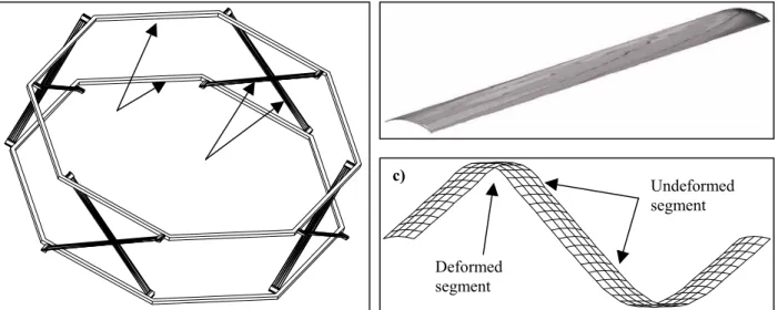
The structure is composed by five octagons realised in stainless steel and carbon fiber and they are connected each other with the tape springs as shown in the drawing of figure 2.1.a. The first octagon is bolted to the satellite and it accommodates the primary mirror of the telescope. The fifth octagon (the last one) is positioned at a distance of 520mm from the first one and it houses the secondary mirror.
Figure 2.1: a) Two Octagons with springs, in deployed configuration;b) A single Lenticular Tape Spring, in deployed configuration; c) A single Lenticular Tape Spring, in stowed configuration
In order to have a precise deployment and a stiff deployed structure, the tape springs are realized curving the section of a flat tape, obtaining a so-called Lenticular Tape Spring3,4. In Figure 2.1.b is shown one of the lenticular springs in
equilibrium configuration. The curved cross section increases the inertia momentum, then the rigidity to the bending and the stability to compression loads5. Moreover the curvature of the tape springs gives a perfectly rectilinear equilibrium
configuration, respect to a flat tape that will never be rectilinear owing to light permanent deformation. Figure 2.1.c shows the characteristic bending of lenticular tape spring when stowed. The deflection is collapsed in short sections of the tape, while the large part of it is without deformations. In the stowed configuration the five octagons are in contact each other and the occupied space is just the sum of their sections . The springs, folded out the equilibrium (as in figure 2.1.c) occupy a height equal to ½ or ¼ of the distance between two consecutive deployed octagons, depending on the number of folds. This deployment system needs a simple retain mechanism, which takes the structure compressed and, once released, it will trigger the deploy.
Because the deploy is spontaneous, it is not controlled. In order to avoid shocks caused by an excessive acceleration and deceleration of the octagons, the springs are realised with a viscoelastic polymer between two steel tapes. During the deployment the two tapes slide one with respect to the other, imposing an intense shear deformation to the polymer. If this deformation is slow, the shear stress is negligible. If the deployment process get too fast the viscous stress in the polymer will slow down the motion of the system.
Octagons Springs a) b) Undeformed segment Deformed segment c)
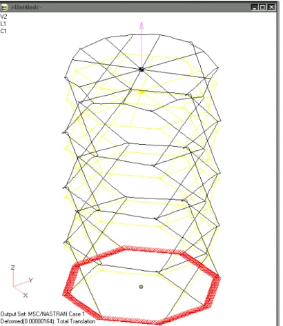
The primary mirror of the telescope is 400mm in diameter. The mirror dimension imposed us to design a structure with octagons of 442mm inscribed diameter where 11mm are for the each of the two springs (a tape is 10mm wide) and 10mm for the internal black blanket (all around the inner part of the structure). The total external diameter of the structure will be 474mm, taking into account the thickness of the external blanket. This dimension of the payload is still compatible with the room for micro-payloads available on board of commercial launch vehicle. In order to position the secondary mirror of the telescope at the required distance (520mm from the optical simulation), the structure has been designed to be 600mm long, once deployed. In the first design phase, the analysis has been focused on the behaviors of the deployed structure. Different finite element schematization have been developed and tested with NASTRAN6.
Figure 1.2 FEM model of the deployed structure
The performances of the telescope are affected by displacements of the secondary. Axial displacement and off axis movements of the mirror cause different effects on the image captured. Axial displacement out of focus system cause an image defocalization and then a loss of resolution. Gravitational gradient, uniform thermal solicitation and effects of the deployment can cause axial displacement of the secondary mirror. In order to evaluate the rigidity of the structure under these loads, the structure has been statically loaded, applying an axial force of one Newton and then the loads imposed by the gravitational acceleration during the tests that will be performed in the future on the ground.
Off axis displacement of the secondary mirror have an even more negative effects on the quality of the captured images. We analyzed the effects of shear loads on the structure, applying a one Newton load to the secondary mirror, along the x direction (see Figure 2.2), perpendicular to the axis of the telescope. The effects of these loads are reported in the table 2.1.
Load Displacement of secondary mirror (mm)
1.0 N 1.3e-3(axial)
1.0g (m.81ms-2) 1.2e-2(axial)
1.0 N (Shear) 5.8e-2 (Off Axis)
We investigate also the structure oscillations. This analysis is particularly important since oscillations with a period comparable to the exposure time of the image linear sensor (20-25 MHz), will cause degradation of the captured images, while the low frequencies oscillation of the deployed structure can have negative effects on the attitude control system of a microsatellite2. Table 2.2 reports, for the different deformations, the characteristic frequencies estimated with the FEM
(Finite Element Modelling) modal analyses performed with NASTRAN.
Mode
number Frequency(Hz) Deformation
1 25 Shear
2 50 Torsion
3 55 Axial
Table 2.2 characteristic frequencies
The frequencies are low, if compared with the exposure time of our linear sensor (30 µs) , and are high, if compared with the characteristic frequencies of the attitude control system of satellites (below 10Hz). All the characteristics of the structure make us confident about its performances in the space, moreover, the structure does not present hinges, bearings or other mechanisms. There are no parts of it in motion , and no joint clearance between the components is required.
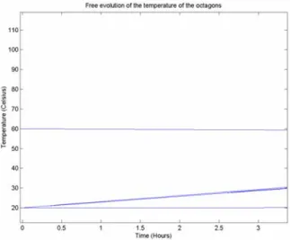
A thermal study on the deployed structure has been performed. The steel of springs and octagons must have almost a constant temperature in order to avoid deformation and then errors in the position of the secondary mirror. Assuming a max allowed deformation of 0.1mm the variation of the temperature will be less than 13˚C. In order to guarantee an almost total insulation from solar radiation and albedo the structure will be enveloped in MultiLayer Insulator blanket (MLI). Owing to the regular shape of the structure, the MLI will work at its best along all the telescope. Anyway we must foresee a no perfect insulation for the octagon number five, where the terminal part of the structure will cause contact between the layers of the MLI and then an increased of the thermal conductibility7. In order to evaluate the
effects of the heating on the octagon number five, we performed a simple numerical simulation.
Figure 2.3 Free temperature evolution of the octagons.
The structure has been divided into five nodes, one for each octagon. We imposed the temperature on the first octagon 20˚C, assuming it in equilibrium with the satellite, and the fifth octagon at 60˚C (a temperature much higher compared to the expected temperature). Figure 2.3 shows the result of our analysis. We notice that the free evolution of the temperature on the three internal octagons is very slow, compared to the orbital period, that is about 1.5 hours. This slow heating is due to the low cross section of the springs, that allow a very little heat transfer. The octagon number five will be heated by sun and albedo only for about one hour, then it will be cooled again in the eclipse phase of the orbit. This
allow us to assume that the heating of the octagon five will stay almost confined in it and will not heat the whole structure that will stay almost isothermal.
3. OPTICS DESIGN
The telescope has a Cassegrain configuration with a parabolic primary mirror and an hyperbolic secondary mirror. It will provide a 2.25 resolution imaging in the visible range of a 4km x 4km area from a 600 Km sun synchronous orbit.To project the telescope we performed simulations with Zemax software8, looking for the best compromise between
compactness, a good aberration correction and an reliable modulation transfer function. The primary and the secondary mirror have a diameter of 40 cm and 10cm with a parabolic and an hyperbolic geometry respectively. The telescope focal length is 2.5 m. In table 3.1 all the telescope characteristics are reported.
Telescope Focal length Distance primary-secondary Primary mirror diameter Primary mirror focal length Primary mirror hole diameter Primary mirror conic coefficient Secondary mirror Diameter Secondary mirror Focal length Secondary mirror Conic coefficient 2.5 m 52 cm 40 cm 69 cm 4 cm -1 10 cm 23 cm -2.8657
Table 3.1 Telescope characteristics
The spherical and the coma aberration have been minimized by using the parabolic and the hyperbolic for the primary and the secondary mirror respectively, while the field curvature has been corrected by putting a doublets of plano-convex lenses outside the telescope having a diameter of 2.5 cm each. In order to minimize the field curvature the lenses have to fulfill the Peztval equation9 n
1f1+n2f2=0, where n1 and f1 are the refractive index and the focal length of the first lens and
n2 and f2 are the refractive index and the focal length of the second lens respectively. It follows that the first lens will be
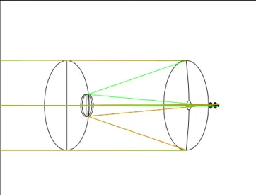
made up of silica with a 13 cm focal length, while the second lens will be made up of BK7 with a 16 cm focal length. In fig 3.1 is reported a simulation of the telescope with the doublets of lenses to correct the field curvature.
Fig 3.1 A Zemax simulation of the cassegrain telescope with the doublets of lenses to correct field curvature
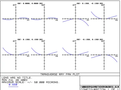
In fig. 3.2 we report the ray transverse aberration showing variation of ray position at the detectors over a field of angles which simulates the 4km x 4km area seen by the telescope from a 600 Km altitude. The variation in intersection position at the detector is plotted in the transverse ray aberration plot to demonstrate blurring in a radial direction for a Y-fan and in saggital direction for the X-fan of about 25 µm for both direction leading to an image degradation of 0.2%, because of the presence of the astigmatism aberration in the telescope due to the non spherically geometry of both mirrors.
Moreover in fig 3.3 it is plotted the modulus of the optical transfer function (i.e. the modulation transfer function) as a function of the spatial frequency for different field angles. This plot shows a good reproduction of the image quality only slightly affected by aberration at the higher spatial frequency values which is consistent with the ray aberration plot.
Fig 3.2 Telescope transverse ray fan aberration
Fig. 3.3 Telescope Modulation transfer function
Moreover simulations of the telescope performances as a function of an axial displacement of the secondary mirror have been performed showing that for axial displacement of the secondary mirror of 0.5 mm, higher than those calculated in table 2.1 the resolution will change of 0.4%. Finally also the possible non axial displacement will not have some consequence on the degradation of the images, as already discussed in section 2.
4. THE SENSOR
To detect images with a 4km x 4 km area , we chose a linear image sensor, the Dalsa, high sensitivity line scan device with 2048 pixels (see fig.4.1). In fact, with a linear progressive scan technology we can utilize satellite tracking for continuous lines acquiring, for the image composition. This technology simplifies all pixels operations for exposure, shutting, reset and data transfer. With a 2 K pixel sensor we can acquire a continual image with a diagonal dimension of 2048 pixels. In table 4.1 we summarise the sensor characteristics.
Fig. 4.1 the Dalsa, high sensitivity line scan device with 2048 pixels Data
Rate resolutionLinear Max. LineRate Max LineTime PixelSize Interfacedigital Powersupply consumptionPower rangeGain
40 MHZ 2048 X 96 17 KHZ 59 us 13x13
pixel
8 bit LVDS 12- 15 V <7 W -8.5 to 9.5 dB
Table 4.1: Dalsa sensor characteristics
This Dalsa sensor is based on the TDI technology (Time Delay and Integration). This method strongly increases the sensor responsivity. It allows a much greater scanning speeds in dark conditions with respect to a conventional linear sensor. This method is based on the multiple exposure accumulation of the same moving object. The sensor is considered as linear, but thanks to the possibility to accumulate multiple exposure it can be considered a rectangular array 2048 for 96 pixels. Many pixels collect and transfer light to follow the observed target up to the final pixel, that so is about pre-charged at the desired value. All the faint images of the same object combine to provide a high contrast clear image. Moreover, we choose a 2048 linear sensor also because, to our best knowledge, it is difficult to realise an electronic or mechanical shutter able to perform the mentioned timing for a 4 M pixel sensor. In fact, owing to the high satellite orbital velocity (7Km/s) a very small exposure time is required, about 30 µs, in order to obtain an 90% pixel coverage. The electronic sensor architecture, requires long time for shutting or resetting operation of each pixels, for each kind of technology used to realise the sensor. In fact each kind of component, CCD or Cmos, is based on a rolling shutter system that doesn’t hide simultaneously all the pixels. With this linear sensor we overcome this problem because all the pixels will be hidden in the same time.
5. CONCLUSION
In the framework of MITAR project funded by ASI (Italian Space Agency), we projected a deployable telescope with a 2.25 m resolution in the visible range on a 4 km x 4 km area The telescope has a Cassegrain configuration with a parabolic primary mirror and a secondary hyperbolic mirror having a diameter of 40 cm and 10cm respectively. The telescope focal length is 2.5 m. The deployable structure is made up of five octagons realised in stainless steel and carbon fiber and connected each other with the tape spring. The first octagon is bolted to the satellite and it accommodates the primary mirror of the telescope. The fifth octagon is positioned at a distance of 520mm from the first
one and it houses the secondary mirror. To detect images we chose a linear image sensor, the Dalsa, high sensitivity line scan device with 2048 pixels, based on the TDI technology (Time Delay and Integration).
6. REFERENCES
1. D'Errico M., Vetrella S., "Mission analysis of an Earth observation microsatellite", 48th IAF Congress, 1997,Torino, Italy
2. M.Pastena, M.Grassi,“Design, development and test of the attitude control subsystem for an earth observation micrsatelite” Paper IAA-B3- 2-6-2001.
3. Seffen, Pellegrino “Deployment dynamics of tape springs” Proceedings of the Royal Society of London, A, 455(1983), pp. 1003-1048
4. Seffen, Pellegrino Folding and deployment of curved tape springa”(1997) Technical report, CUED/D-STRUCT/TR171
5. Timoshenko, Theory of elastic stability, .mcgraw-hill publishing company
6. NASA STructural Analisys. By The Macneal Schwendler Corporation (www.mscsoftware.com) 7. Satellite thermal handbook. David G. Gilmore editor
8. Zemax, Optical design program User Guide 8.0, 1999