Volume 12, Issue 12 (December 2016), PP.45-55
Numerical Analysis of Continuous Variable Valve Lift (CVVL)
Mechanisms for Throttle Free Load Control of SI Engine
MeghaA. Mohite
1, EknathN. Aitavade
2, Santosh.B. Trimbake
3 1,2Ashokrao Mane Group of Institutons, Vathar, Kolhapur, India
3
College of Military Engineering, Pune, India
Abstract:
Variable Valve Actuation (VVA) systems are being extensively used in internal combustion engine. In such mechanism, cams and valves are connected via intermediate lever, which allows different maximum valve lifts and duration using same cam profile. Recently, novel valve actuation mechanism like continuous variable valve lift (CVVL) is being explored to regulate engine output without conventional throttle valve and this reduces the pumping losses especially at part load in SI engines.CVVL mechanism with three elements consists of eccentric shaft fitted with a series of intermediate rocker arm, which in turn control the degree of valve lift. By optimizing, the fuel/air mix process, this mechanism produces fuel savings of up to 10 percent. In addition, it improves cold start behavior, lowers exhaust emissions and provides more power.
This paper presents the kinematic analysis of novel CVVL mechanism with three elements for small capacity single cylinder motorcycle engine. It comprises ofa controlled shaft, standard roller follower, the c a ms h a f t , and anintermediaterockerarmusedbetweenthem.The inter media terockerar misequipped with a special developed contact surface, which is based on the theory of envelop curves and has a plane- parallel motion which ensures a continuous valve lift (VVL System) between two extreme heights.
Numerical simulation carried out in MATLAB, shows that the mechanism continuously varies valve lift height while the valves opening time remains constant.
Thegeneralcondition to design a mechanism for continuous VVL has been evaluated. Using a semi- elliptical cam profile, the kinematic analysis of the mechanism proceeds, resulting in the family of the valve lift laws. Numerical simulation carried out in Ricardo VALDYN-Kinematics, shows that the mechanism continuously varies valve lift. Further Kinematic analysis of the same mechanism is evaluated, which includes valve lift, velocity, acceleration. The numerical results, such as valve lift variation at different operating conditions; velocity and acceleration are compared and found to be in good agreement under the given set of operating conditions.
Keywords:
CVVL - Continuous Variable Valve Lift, Kinematic Analysis, Valve lift law, Controlled shaft and
Intermediate leverI.
INTRODUCTION
The design of an internal combustion (IC) engine is a complex compromise between performance, fuel economy and emissions. These three factors are interrelated and they cannot be simultaneously optimized. Furthermore, once the physical parameters such as displacement, cam profile and compression ratio are determined, a conventional engine has nearly fixed performance, fuel economy and emissions properties. By making an engine more efficient, one or more of these factors could be increased without significantly compromising the others.
Thermodynamics shows that the higher an engine‟s compression ratio, the higher its efficiency. However, the in-cylinder pressures and temperatures which result from higher compression ratios place an upper bound on an engine‟s compression ratio. The cause of this limiting is largely engine knock or auto-ignition. When an engine starts knocking, the progressive normal combustion is replaced by very fast detonation waves in the combustion chamber, and the engine can be severely damaged. Another method of increasing the efficiency of an engine is reducing the mechanical losses associated with throttling. When an engine is throttling, a plate obstructs the air intake flow and causes a pressure drop across the plate. Throttling reduces the amount of air induced into the engine, but it introduces flow losses which reduce an engine‟s efficiency.
environmental, and efficiency requirements for IC engines can be and have been satisfied. However, increasing demands for improved fuel economy and stringent government regulations on exhaust emissions begin to motivate many researchers and engineers to explore alternative means in which the valve motions are no longer fixed to the crankshaft position. In this new approach, referred to as Variable Valve Actuation (VVA) engine technology, additional degrees of freedom allow the Valve events to be selectively optimized and controlled to provide a unique valve motion for each region of engine operating conditions to present the optimal engine performance, emissions, and fuel economy benefits at each particular operating region.
II.
BACKGROUND AND OBJECTIVE
The current methodology enables the design of the valve train systems. Some of the recent investigations are presented below:
In order to generate an entire range of valve lift laws, as shown in figure 1, it is necessary to use timing mechanism, which comprises adjustment elements to ensure this effect.[1]
Figure.1 Engine load control by variation of intake valve lift
The variation of the valve lift using cams with stair shape is used by Audi with AVS (Audi Valve lift System). The system achieves a discrete variation of the valve lift and is used on gasoline engines 2.8 FSI and 3.2 V6 FSI. The system consists in two cams with two profiles. At high loads, the cams lift with 11 mm, while at medium and low loads they lift with only 5.7mm and 2 mm, respectively. Honda VTEC (Variable valve Timing Electronic lift Control) ensures two stages of valve lift. The mechanism has two „„small‟‟ cams for partial loads and a „„large‟‟ cam for high loads. The system is electronically controlled. Toyota VVTL-i ensures: the continuity of the distribution phases, the two-step variation of the valve lift, and the time of opening for both the inlet and exhaust valves. This system is used for both valves. Similar to Honda‟s system, the Toyota system also has a cam with two shapes. Delphi 2-Step Valve Lift System uses a cam with three lobes: the central one is for the maximum opening of the valve, while the other two are for the minimum opening. FIAT was the first company which patented and used (at the end of the 1960s) spatial cams on camshafts with axial displacements.
BMW Valvetronic ensures the continuous variation of the valve lift using planar cams. The system was launched in 2001 on the model 316 Ti Compact. It uses an electric motor that acts upon an eccentric control axle. Ford Motor Company achieves the variation of the valve lift by modifying the active lengths of certain arms in the kinematic chain [1].
S. Mihalcea, N. Stanescu and D.popa[1] have presented a new type of continuously variable valve lift (VVL) system. When the rotation angle of the adjustment shaft is controlled, the valve lift height is also controlled. The profile of the contact surface is analytically determined using the theory of the envelope curves. Using a certain cam profile, the kinematic analysis of the mechanism proceeds, resulting in the family of the valve lift laws. This workestablishes the general conditions to design a variable valve timing (VVT) mechanism with continuous VVL and mechanical actuation.
S. B. Trimbake, Dr. D. N. Malkhede[2] have presented a flexible and practical approach to achieving SI and CAI combustion in a four stroke gasoline engine has been developed by making use of mechanical variable valve lift. In this paper Valvetronic system which offers the phenomenon of continuous Variable Valve Lift is discussed.
S. Mihalcea and N. Pandrea [4]have presented an innovating solution for throttle-free load control for spark-ignition engines is variable valve timing system. In this paper is presented a kinematic analysis, using the analytic method, of the valve timing mechanism with three elements and continuous valve lift variation. It is also presented the numerical algorithm for the mechanism‟s motion.
P. K. Wong and K.W. Mok[5] have introduced a novel design named dual-mode electro-hydraulic fully variable valve train for both engine intake and exhaust valves. Experimental and simulation results showed that the dual-mode electro-hydraulic variable valve train can achieve fully VVT and lift control, and has the potential to eliminate the traditional throttle valve in the gasoline engines. As claimed the engine performance at various speeds and loads can be significantly improved.
Yasukazu Sato, Yukinori Nishimoto, Yoshitomo Fukushima and Takuya Nagataki [6] presented a highly reliable VVL mechanism controlled by a hydraulic 3-step rotary actuator. 3-step VVL with high-, middle- and low-valve lift, is realized by the pivot shifting of an intermediate cam placed between a camshaft and valve tappet.
III.
CONTINUOUS VARIABLE VALVE LIFT (CVVL) MECHANISM
Continuous variable valve actuation mechanism allows the valvelift to continuo uslychange according to various engine operating conditions.Even though this type of system is typically more complex , costly ,and difficult toimple mentin power train,it generally carries greater potential benefitsinterms of fuel economy, exhaust emission, and engine performance.
The CVVL mechanism mainlyconsists of the following components: electricmotor, eccentric shaft, intermediate lever , roller rockerarm , and cam/ camshaft. Them otor turns the eccentric shaft which moves the intermediate lever backand forth. The intermediate lever has a roller in the middle which is in direct contact with the cam. The upper end of the leve risin contact with the eccen tricshaft while its lowerendis incontact with the roller rocker arm, which eventually activates the valve motion, as shown in Figure 2.
Figure 2. Description of CVVL Mechanism[7]
In the case of nor low lift , the motor turns the eccentricshaft so that the contact surface between the intermediate elever and the roller rockerarm remainsal most flat. In thiscase, the roller rockerarm moves only along the flat surface so that the rotation of cam shaft produces nor very small valveliftas intended.
In the case of highlift , however , the motor turns the eccentric shaftso that the contact surface between the intermediate elever and the roller rockerarm become smore round. The roller rockerarm then moves along the rounded surface so that the rotation of camshafttnow result sinahighlift of theintakevalve. Basedonthisoperatingprinciple,thesystemcangenerate the intake valve lift profile [7].
Numerical Modelling Of Vvl Mechanism
Advances in computational methods and the availability of high speed computers have made it possible for the researchers to analyze valve lift process in an IC Engine. Experimental study requires enormous time, manpower, material and financial resources. However, the use of simulation software has made it more advantageous over experimental study. The current study uses MATLAB and VALDYN Kinematics to analyze the valve lift mechanism in single cylinder SI Engine.
4.1 Numerical Modelling Of Cvvl Mechanism With “Matlab”
roller rocker finger (3) via the rocker arm (2) which is equipped with a working curve. The rocker arm is in a direct and permanent support with the camshaft, the eccentric control shaft and the roller rocker finger with the working curve. For each angle of the control shaft, there is a maximum and fixed intake valve lift. Variation of the valve lift is achieved by modifying the eccentric shaft position. For the proposed mechanism, the kinematic schema is showed in figure 4.2, accordingly with the notations there are 4 sliding contact between the elements
4 3 2 1
,
C
,
C
,
C
C
. Also the camshaft and the roller rocker finger are articulated with the base (cylinder head) inO1 and O4. Therefore, the mechanism‟s mobility is unique, as it results from [3]:
1
4
2
2
3
3
2
3
5 43
n
c
c
M
The eccentric control shaft has no influence on the mechanism‟s mobility because its position is stationary. The general coordinate system is O0XY, the camshaft (1) local coordinate system is O0XY where O1
is identically positioned with O0, the rocker arm (2) local coordinate system is O2x2y2 where point A is placed on
the O2y2 axis, the roller rocker finger (3) local coordinate system is O3x3y3 where point E is placed on the O3x3
axis.
Figure.3 Kinematic Schematic of mechanism
When the eccentric shaft is turning, measured with the angle
[
min:
max]
, the rocker arm (2) is turning around the point O2, the contact C4 with the roller rocker (3) describes a contact curve (working curve)
C
, which is actually the DH circle arch byR
2' radius, the point D matches the
minangle and point H to themax
.To ensure the permanent contact between elements (2) and (3) is necessary to extend the
C
curve with two circle arches DG, HK, and so results the contact curve (working curve)
.Some notations are used:
ll=O2A, l2=O4B, l3=O3E, l4=O3O5, l5=O3P;
r1, r2, R1, R2 , r4 , rA , rB , rE , rD, ,rH , for the circle radii in figure 4.2;
*,
*,
*, on the mechanism‟s reference position (ϕ=ϕ*=0), between O0O2 , O2x2 , O3E axis and O0X axis;
also are used some secondary angles
2,,
3,
4to define the contact equations for C2 , C3 , and C4 points as shown in figure 4.3.
O3 (X3, Y3) and O4(X4, Y4) point coordinates in the main coordinates system O0XY
The tangency and contact equations in point C1 are obtained:
sin
0
cos
1 11
1
x
p
y
p
f
(1)
sin
cos
0
cos
1 2 1 21
2
x
y
r
X
f
(2)
cos
sin
0
sin
1 2 1 21
3
x
y
r
Y
f
(3)
Where x1p and y1p are the x1 and y1 derivate with cam rotation angle Φ.β is the angle which defines the cam position in its coordinate system, X2 and Y2 are the O2 point coordinate in the general system O0XY.
Figure 4 The C1 contact point
on the base cam circle
Knowing the
2 angle between O2O4 and O0Y axis, for the tangency contact point C2 the following equationsare obtained:
0
sin
)
(
2 4 2 42
4
X
R
r
X
f
(4)0
cos
)
(
2 4 2 42
5
Y
R
r
Y
f
(5)In the same way, knowing then 3
angle between AB segment and O0X axis, for the contact and tangency point C3 the following equations are obtained:
0
cos
cos
)
(
sin
3 4 21 2
6
X
l
r
r
X
l
f
A B (6)0
sin
sin
)
(
cos
3 4 22 2
7
Y
l
r
r
Y
l
f
A B (7)For the contact and tangency in C4 point, using the
4angle between EC4 segment and O0Y axis and knowing equations 4.27 and 4.28, results:0
sin
cos
sin
cos
3 4 32
8
X
x
y
l
r
X
f
r
r
E
(8)0
cos
sin
cos
sin
3 4 32
9
Y
x
y
l
r
Y
f
r
r
E
(9)0
)
cos(
)
sin(
4 410
x
p
y
p
f
(10) Where, min min min)
2
cos(
)
2
sin(
if
r
y
r
x
D p D p
sin
* 2R
x
p
cos
* 2
R
y
p
)
2
sin(
max
p
r
Hx
)
2
cos(
max
p
r
Hy
Equations
f
1
0
,
i
1
,
2
,..
10
,
form a system from where
,
1,
2,
3,
4,
X
2,
Y
2,
,
,
parameters are obtained for
1
360
0. The equation system is easily solved using the numerical computing methodNewton-Raphson, in which, the initial values are
*,
1*,
2*,
3*,
4*,
X
2*,
Y
2*,
*,
*,
.Using the following equation: 5 6l
l
arccros
(11)Results the valve lift law:
sin
sin(
)
)
(
l
6
*s
The intermediaterockerarmisequipped withaspecialdevelopedcontactsurface, which is based on the theory of envelop curves and has a plane- parallel motion. To obtain contact curve the above equations are solved using MATLAB tool and it found to be in good agreement with literature as shown in figure 5.
Figure 5 Contact curve of intermediate lever
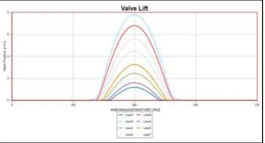
Figure 6 Valve Lift at various control angles
To obtain family of valve lift, the contact curve equations for regular and extended curves are solved using the Newton Raphson method. This method is explained in the flowchart shown below. The matrix [F] is the row matrix of function given by equations 1 to 10. Matrix [dF] is the Jacobean matrix of 10 × 10. First element is the partial differentiation of f1 w.r.t first unknown. Similarly, for second element, second unknown is used. After this matrix is completed, using equation [dX]= [dF]\[F], the difference of unknowns is obtained. This matrix is used for second iteration if the error is more than the required error and this process is continued
for each
value from 0 to 360 degrees. Again this process is repeated for all
values. From these iterations we obtain
value for each
and each
. Then using equation 12, lift values are obtained as shown in figure 6.4.2 Numerical Modelling Of Cvvl Mechanism With “Valdyn Kinematics”
4.2.1 Valdyn Kinematic Basics
The VALDYN Kinematic Solver [8] is a program for the design and kinematic analysis of valvetrain systems. It uses a building block approach so that standard and unconventional valvetrains or partial valvetrains can be modelled. All the common valvetrain types can be analyzed such as linearly translating followers and swinging followers with or without a push rod and rocker system, as well as continuously varying valve lift (CVVL) systems. The program can either be used to assess an existing cam design or can be used to generate a cam profile using the Ricardo ‟Multipol‟ technique. This is a spline type technique developed at Ricardo for quick and easy optimization of automotive and heavy duty engine valve profiles.
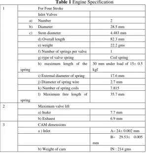
1.2.1.1 Model development
Table 1 Engine Specification
1 For Four Stroke
Inlet Valves
a) Number 2
b) Diameter 28.5 mm
c) Stem diameter 4.483 mm
d) Overall length 82.3 mm
e) weight 22.2 gms
f) Number of springs per valve 1
g) type of valve spring Coil spring
h) maximum length of the spring
30 mm under load of 15± 0.5 kgf
i) External diameter of spring 17.6 mm
j) Diameter of spring wire 2.7 mm
k) Number of spring coils 7.815
l) Maximum free length of spring
35.7 mm
2 Maximum valve lift
a) Inake 7.7 mm
b) Exhaust 6.9 mm
3 CAM dimensions
a ) Inlet A= 24± 0.002 mm
B= 29.53± 0.005 mm
b) Weight of cam IN : 214 gms
To change the valve lift, eccentric cam shaft is rotated. InVALDYN, the position of Intermediate arm is rotated by giving the parameter “angle”. For each case different angle is activated and valve lift is changed.
Table 2 Components used in model
Sr.No. Component Mass Material Initial position
X Y
1 Rocker arm 50 Steel 0 0
2 Intermediate
Arm
60 Steel 25 67.5
3 Cam 30 Steel 53.5 37.05
4 Valve 10 Steel 45 -5
Figure 7 Mechanism Model Figure 8 Mechanism layout according to position
1.2.1.2 Solution Setup
Table 3input parameterin model
Sr.No. Parameter Value
1 Maximum angle to analyze 360
2 Angle to start output 90
3 Angle increment for output 15
4 Excitation speed parameter name Omega
5 Maximum number of iterations 20
The table 4 shows the cases used and the above parameters value given in solution mode. Eightcases areused to obtain different valve liftsas shown in table 4. Omega is constant because it will not have any effect on the valve lift profile in kinematic solution. Angle parameter corresponds to the degree rotation of intermediate arm according to the degree rotation of eccentric cam shaft. After these parameters are set, solution is run to obtain the results. After this setup is done solution is run for all cases to get the results in Result Mode.
Table 4 Angle correspondence in solution mode
Sr. No. Case No. Eccentric shaft Angle Case Angle
1 1 0 5.5
2 2 30 4.5
3 3 60 2.8
4 4 80 1.5
5 5 100 -0.2
6 6 115 -1.5
7 7 130 -2.8
8 8 155 -3.8
IV.
RESULTS AND DISCUSSION
In kinematic analysis of mechanism, focus is on valve lift, velocity and acceleration profiles. Figure 9 shows the valve lift profiles for different cases. Similarly figure 10 and 11 shows respective velocity and acceleration profiles.The valve motion can be split into five stages [9].
1. Before the valve starts to move, the clearance between the follower and the valve tiphas to be taken up. This clearance ensures the valve can seat under all operatingconditions and allows for bedding-in of the valve. The cam is designed to give aninitially constant velocity to control the impact stresses as the clearance is taken up.The impact velocity is typically limited to 500 mm/s at the rated engine speed.
2. During the next stage the cam accelerates the valve. Rather than designing the camto give the valve a constant acceleration (which would lead to shock loadings),sinusoidal functions which cause the acceleration to rise from zeroto a maximum and then fall back to zero, are used.
3. Deceleration is controlled by the valve spring as the valve approaches maximum lift.As the valve starts to close, acceleration is also controlled in this way.
4. Final deceleration is controlled by the cam.
5. The cam is designed to give a constant closing velocity in order to limit impactstresses.
Figure 10 Velocity profile at different control angles
Figure 11 Acceleration profile at different control angles
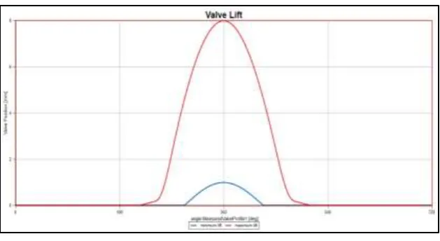
Figure 12 Valve lift profiles
Valve lift for maximum and minimum control positions of the eccentric shaft are shown in figure 12. It is seen that the maximum valve lift of 7.7 mm is achieved while the minimum valve lift of 1.2mm is achieved. The area under the curve is also changed in both the cases. Therefore, less air enters when the valve lift is low, as the effective duration of valve opening and closing is reduced. Hence the purpose of throttle free load control can be achieved.
1. Minimum lift
Figure 13 Minimum lift
Maximum lift
Figure 14 shows the results obtained from matlabandvaldyn.From the figure 14 it is seen that all the results match in good agreement. The maximum lift of around 7.7 mm is achieved.
Figure 14 Maximum lift
V.
CONCLUSIONS
This paper presents numerical kinematic analysis, for a CVVL mechanism with three elements and an arbitrary contact curve. The contact curve development is based on the theory of envelope curves, for a continuous CVVL mechanism. This contact curve allows a correct valve lift adjustment.
1. The profile of contact surface which includes regular and extended curves is numerically determined using the theory of envelop curves shows in good agreement with the published literature data.
2. The kinematic analysis shows that the mechanism ensures a continuous valve lift between two extreme valve heights i.e. from minimum 1.2mm to maximum 7.7 mm.
3. By varying the control angle of the eccentric shaft from 0o to 155o, results in family of valve lift laws which also show good agreement with the published literature.
4. Kinematic analysis using numerical method like MATLAB and commercial available simulation software Ricardo Valdyn-Kinematics is carried out and found to be in good agreement with each other.
5. The proposed CVVLmechanism is successfully numerically analyze for 200cc DOHC single cylinder four valve motorcycle engine and demonstrates the continuous variable valve lift for same engine.
REFERENCES
[1]. StelianMichalcea, N.D. Stanescu and DinelPopa, "Synthesis and Kinematic and dynamic Analysis of a variable valve lift mechanism with General Curve Contact", Journal of multibody dynamics 2015, vol. 229(l) 65-83, Sage.
[2]. S. B. Trimbake and Dr. D. N. Malkhede - “Strategies for HCCI/CAI Combustion Control using Residual Gas”
[3]. S. Mihalcea.,“A kinematic analysis of the valve timing mechanism with three elements and continuous valve lift”, ISSN 1453-7397, 2010.
[4]. StelianMihalcea and NicolaePandrea., “A Kinematic Analysis of the Variable Valve Timing Mechanism with Three Elements and Continuous Valve Lift”, ISSN 1844-640x, 2010.
-5 0 5 10
0 100 200 300 400 500 600 700 800
Maximum Lift
valdyn profile Matlab profile
-0.500 0.000 0.500 1.000 1.500
0 100 200 300 400 500 600 700 800
Minimum Valve Lift
[5]. P.K. Wong and K.W. Mok University of Macau- “Design and Modeling of a Novel Electromechanical Fully Variable Valve System”. SAE 2008 Paper no. 2008-01-1733
[6]. Yasukazu Sato, Yukinori Nishimoto, Yoshitomo Fukushima and Takuya Nagataki- “Automotive variable engine Valve Lift Mechanism controlled by a Hydraulic 3-step Rotary Actuator”, 7th JFPS International Symposium on Fluid Power, TOYAMA 2008 September 15-18, 2008
[7]. Byungho Lee, „Methodology for Rapid Static and Dynamic Model-Based Engine Calibration and Optimization‟, PhD Thesis, Ohio State University, 2005.
[8]. VALDYN Kinematics User Manual, Ricardo Software, Version: 2015.1
![Figure 2. Description of CVVL Mechanism[7] In the case of nor low lift , the motor turns the eccentricshaft so that the contact surface between the](https://thumb-us.123doks.com/thumbv2/123dok_us/1405658.1652870/3.595.165.438.387.522/figure-description-cvvl-mechanism-motor-eccentricshaft-contact-surface.webp)