[Mohite* 4(10): October, 2017] ISSN 2349-4506
Impact Factor: 2.785
G
lobal
J
ournal of
E
ngineering
S
cience and
R
esearch
M
anagement
FEA BASED NUMERICAL MODELLING OF CONTINUOUS VARIABLE VALVE
LIFT MECHANISM FOR SINGLE CYLINDER SI ENGINE
Megha A. Mohite*, Santosh B. Trimbake, Vinay B. Ugale
*Mechanical Department, Collage of Military Engineering, Pune, India
DOI: 10.5281/zenodo.1034493
KEYWORDS
:
VVA-Variable Valve Actuation, CVVL- Continuous Variable Valve Lift, FEA, ANSYS.ABSTRACT
Recently Variable Valve Actuation (VVA) systems are being extensively used in internal combustion engine. In such mechanism, cams and valves are connected via intermediate lever, which allows different maximum valve lifts and duration using same cam profile. Recently, novel valve actuation mechanism like Continuous Variable Valve Lift (CVVL) is being explored to regulate engine output without conventional throttle valve and this reduces the pumping losses especially at part load in SI engines. CVVL mechanism with three elements consists of eccentric shaft, Intermediate lever and Rocker arm, which in turn control the degree of valve lift. It ensures a continuous valve lift between two extreme heights.
This paper presents the development and evaluation of a Numerical model of novel CVVL mechanism on FEA platform using ANSYS 14.5, for small capacity single cylinder motorcycle engine. From the design point of view, on the strength basis all the critical components of CVVL mechanism with respective selected material were analyzed using developed numerical model in ANSYS 14.5 and compared with analytical results. Numerical results were found to be in good agreement with analytical one for the given set of conditions.
INTRODUCTION
The design of an IC engine is a complex compromise between performance, fuel economy and emissions. These factors are interrelated and cannot be simultaneously optimized. Once the physical parameters such as displacement, cam profile and compression ratio are determined, a conventional engine has nearly fixed performance, fuel economy and emissions properties. By making an engine more efficient, one or more of these factors could be increased without significantly compromising the others [1-3].
Conventional IC engines have mechanically-actuated valve motions, fixed with respect to the crankshaft position for all engine operating conditions. These valve motions (such as valve lift profile, event timing, and opening duration) are determined during the engine design stage by fixing the cam profile and its position. As such, the valve motions contain a number of engineering trade-offs involving engine performance, exhaust emissions, and fuel consumption over a full range of engine operating conditions. Until now, these technical compromises have been generally accepted within the industry because the performance, environmental, and efficiency requirements for IC engines can be and have been satisfied. However, increasing demands for improved fuel economy and stringent government regulations on exhaust emissions begin to motivate many researchers and engineers to explore alternative means in which the valve motions are no longer fixed to the crankshaft position. In this new approach, referred to as Variable Valve Actuation (VVA) engine technology, additional degrees of freedom allow the Valve events to be selectively optimized and controlled to provide a unique valve motion for each region of engine operating conditions to present the optimal engine performance, emissions, and fuel economy benefits at each particular operating region.
[Mohite* 4(10): October, 2017] ISSN 2349-4506
Impact Factor: 2.785
G
lobal
J
ournal of
E
ngineering
S
cience and
R
esearch
M
anagement
Thus in present work it is proposed to develop and evaluate a Numerical model on FEA platform using ANSYS of Continuous Variable Valve Lift mechanism for throttle free load control of Spark Ignition (SI) motorcycle engine.
CONTINUOUS VARIABLE VALVE LIFT (CVVL) MECHANISM
Continuous variable valve actuation mechanism allows the valve lift to continuously change according to various engine operating conditions. Even though this type of system is typically more complex, costly, and difficult to implement in powertrain, it generally carries greater potential benefits in terms of fuel economy, exhaust emission, and engine performance [1-5].
Figure 1. Description of CVVL Mechanism [2] Figure 2. Line diagram of CVVL Mechanism
The CVVL mechanism mainly consists of the following components: electric motor, eccentric shaft, intermediate lever, roller rocker arm, and cam/ camshaft. The motor turns the eccentric shaft which moves the intermediate lever back and forth. The intermediate lever has a roller in the middle which is in direct contact with the cam. The upper end of the lever is in contact with the eccentric shaft while its lower end is in contact with the roller rocker arm, which eventually activates the valve motion, as shown in Figure1 and 2 [2].In the case of no or low lift, the motor turns the eccentric shaft so that the contact surface between the intermediate lever and the roller rocker arm remains almost flat. In this case, the roller rocker arm moves only along the flat surface so that the rotation of cam shaft produces no or very small valve lift as intended.
In the case of high lift, however, the motor turns the eccentric shaft so that the contact surface between the intermediate lever and the roller rocker arm becomes more round. The roller rocker arm then moves along the rounded surface so that the rotation of camshaft now results in a high lift of the intake valve. Based on this operating principle, the system can generate the intake valve lift profile [3].
[Mohite* 4(10): October, 2017] ISSN 2349-4506
Impact Factor: 2.785
G
lobal
J
ournal of
E
ngineering
S
cience and
R
esearch
M
anagement
ANALYTICAL DESIGN
Material Selection [6]
For the design purpose, suitable material is selected based on selection criteria requisite for the critical components of CVVL mechanism. Properties of selected materials are taken into consideration for the calculation of permissible stresses.
Table 1 Material selection Sr.
No
Name of
component
Selection criteria Material selected Mechanical properties
1 Rocker Arm and Intermediate lever
1.Corrosion resistance 2.Wear resistance
Alloy steel 35Ni1Cr60
1. Yield stress (𝑆𝑦𝑡)
=680N/mm2
2. Ultimate stress (𝑆𝑢𝑡)
=520 N/mm2
2 Torsion Spring
1.Moderate elevated temperatures
2.Shock resistance
Patented and cold-drawn steel wires (Grade 4)
1. Minimum tensile strength =1610N/mm2
2. Modulus of rigidity =81370N/mm2
Design of Components
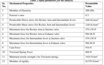
Table 2 Input parameters for the analysis Sr.
No.
Mechanical Properties Permissible
Value
1 Modulus of Elasticity 200 GPa 2 Poisson’s ratio 0.3
3 Permissible Direct stress (for Rocker Arm and Intermediate lever) 260 𝑁/𝑚𝑚2
4 Permissible Shear stress (for Rocker Arm and Intermediate lever) 130 𝑁/𝑚𝑚2
5 Maximum force for Rocker Arm at Suction valve 479.136 N 6 Maximum force for Rocker Arm at Exhaust valve 904.96 N 7 Maximum force for Intermediate lever at Suction valve 479.136 N 8 Maximum force for Intermediate lever at Exhaust valve 904.96 N
9 Cam Force 916 N
10 Torsional Spring Force 606 N 11 Minimum tensile strength ( for Torsional spring) 1610 N/mm2
12 Modulus of rigidity 81370 N/mm2
The critical components of the mechanism namely, Rocker arm, Intermediate lever and Torsion spring was designed on the strength basis, under the wide open throttle (WOT) and maximum speed condition.
[Mohite* 4(10): October, 2017] ISSN 2349-4506
Impact Factor: 2.785
G
lobal
J
ournal of
E
ngineering
S
cience and
R
esearch
M
anagement
The intermediate lever has a roller in the middle which is in direct contact with the cam. The upper end of the lever is in contact with the eccentric shaft while its lower end is in contact With the roller rocker arm, which eventually activates the valve motion.
A helical torsion spring is used to transmit the torque to a particular component of a mechanism. Table 2 gives the input parameters required for the analysis.
Analytical design of components [7]
As mentioned above, apart from standard component (Poppet valve and helical spring) remaining components were designed analytically on strength basis with the help of input parameters as shown in table 2. The results obtained in terms of stresses (compressive and/or bending stresses) are as shown beneath in table 3.
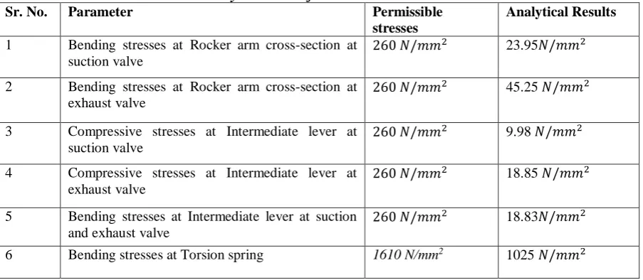
Table 3 Analytical results for suction and exhaust valve
Sr. No. Parameter Permissible
stresses
Analytical Results
1 Bending stresses at Rocker arm cross-section at suction valve
260 𝑁/𝑚𝑚2 23.95𝑁/𝑚𝑚2
2 Bending stresses at Rocker arm cross-section at exhaust valve
260 𝑁/𝑚𝑚2 45.25 𝑁/𝑚𝑚2
3 Compressive stresses at Intermediate lever at suction valve
260 𝑁/𝑚𝑚2 9.98 𝑁/𝑚𝑚2
4 Compressive stresses at Intermediate lever at exhaust valve
260 𝑁/𝑚𝑚2 18.85 𝑁/𝑚𝑚2
5 Bending stresses at Intermediate lever at suction and exhaust valve
260 𝑁/𝑚𝑚2 18.83𝑁/𝑚𝑚2
6 Bending stresses at Torsion spring 1610 N/mm2 1025 𝑁/𝑚𝑚2
NUMERICAL MODEL WITH ANSYS 14.5 SOFTWARE [8]
STATIC STRUCTURAL NON-LINEAR ANALYSIS IN ANSYS 14.5[8] Geometry Simplifications
To reduce the complexity of the finite element modeling we have neglected minute details like small fillets, details of rollers etc.
Meshing Strategy
Rocker Arm is having regular shaped geometry so by slicing the geometry into small parts; rocker arm can be meshed easily with lower order tetrahedral elements. Intermediate Lever is bit complex to mesh with so after simplifying the geometry, they are meshed with lower order tetrahedral elements .Finalization of element size is done on the basis of stress convergence.
In real life, the stress distribution over any component is uniform, and doesn’t always vary abruptly from one point to its subsequent point. In software, each node which is obtained by discretizing the model is having different stress value. The accuracy of this uniformity within the stress distribution depends upon the discretization quality and also the element size used to mesh the component.
[Mohite* 4(10): October, 2017] ISSN 2349-4506
Impact Factor: 2.785
G
lobal
J
ournal of
E
ngineering
S
cience and
R
esearch
M
anagement
We have to go with trial and error method to acquire such element sizes, so that the difference will be less than 10%between two consequent stress values.
After getting those two element sizes, the decision has to be taken according to the node count of the FEA model for respective mesh sizes that which mesh size should be taken for further analysis.
Loading and Boundary Conditions
Boundary conditions for Rocker arm are provided by applying all degrees of freedom zero at fulcrum pin. For Intermediate lever which is dynamically constrained component and eccentric shaft being fixed, the degrees of freedom at upper end of the intermediate lever is zero. For the Torsional spring, at one end all degrees of freedom is zero whereas force is applied at another end.
After meshing, boundary conditions and loads are applied on the nodes and then solver is set to obtain the solution. Further in Postprocessor results are analyzed. Von-Mises Stress plots are taken for visualization and interpretation of results. Maximum stresses are visualized at the sharp corners and thin sections. The same procedure is followed for the structural analysis of other components like Intermediate lever and Torsion spring.
Design of component 1) Rocker Arm
Simplified geometry Model and meshed component
Figure 4 Baseline model Figure 5 Meshed FEA model
Stresses at suction valve
[Mohite* 4(10): October, 2017] ISSN 2349-4506
Impact Factor: 2.785
G
lobal
J
ournal of
E
ngineering
S
cience and
R
esearch
M
anagement
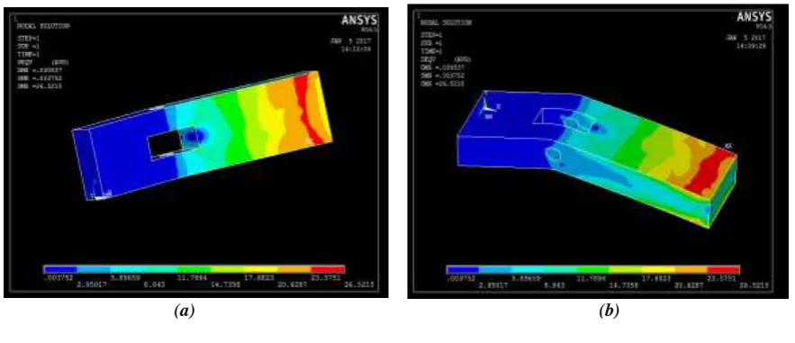
(c) (d)
Figure 6 Von-Mises stress plot at suction valve of Rocker arm
Stresses at exhaust valve
Figure 7 Von-Mises stress plot at exhaust valve of Rocker arm
Von Mises stresses of Rocker arm are 26.52N/mm2 at suction valve and 51.01 N/mm2 at exhaust valve. Maximum
stresses occur at the end of rocker cross section and at the corners roller slot due to sharp corners.
[Mohite* 4(10): October, 2017] ISSN 2349-4506
Impact Factor: 2.785
G
lobal
J
ournal of
E
ngineering
S
cience and
R
esearch
M
anagement
Intermediate Lever Simplified geometry Model and Meshed Component
Figure 9 Baseline model Figure 10 Meshed FEA model
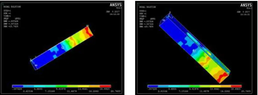
Stresses at suction valve
Figure 11 Von-Mises stress plot at suction valve of Intermediate lever
Stresses at exhaust valve
[Mohite* 4(10): October, 2017] ISSN 2349-4506
Impact Factor: 2.785
G
lobal
J
ournal of
E
ngineering
S
cience and
R
esearch
M
anagement
Von Mises stresses of Intermediate lever are 13.28 N/mm2 at suction valve and 20.76N/mm2 at exhaust valve.
Maximum stresses occur at the corners roller slot due to sharp corners which induces the stress concentration at corners and at the center of Intermediate lever due to thin section.
Torsion spring
Simplified geometry Model and Meshed Component
Figure 13 Baseline model Figure 14 Meshed FEA model
Stresses at torsion spring
Figure 15 Von-Mises stress plot for Torsion spring
Stress of Torsion spring obtained is 1120 N/mm2 which is within the permissible limit hence safe
RESULTS AND DISCUSSION
Comparison of FEA results with Analytical results
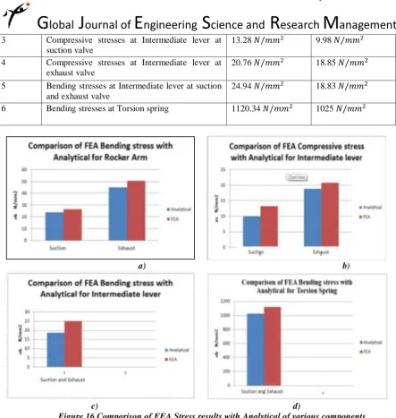
Table 4 Comparison of FEA Stress results with Analytical
Sr. No. Parameter FEA results Analytical Results
1 Bending stresses at Rocker arm cross-section at suction valve
26.52 𝑁/𝑚𝑚2 23.95𝑁/𝑚𝑚2
2 Bending stresses at Rocker arm cross-section at exhaust valve
[Mohite* 4(10): October, 2017] ISSN 2349-4506
Impact Factor: 2.785
G
lobal
J
ournal of
E
ngineering
S
cience and
R
esearch
M
anagement
3 Compressive stresses at Intermediate lever at suction valve
13.28 𝑁/𝑚𝑚2 9.98 𝑁/𝑚𝑚2
4 Compressive stresses at Intermediate lever at exhaust valve
20.76 𝑁/𝑚𝑚2 18.85 𝑁/𝑚𝑚2
5 Bending stresses at Intermediate lever at suction and exhaust valve
24.94 𝑁/𝑚𝑚2 18.83 𝑁/𝑚𝑚2
6 Bending stresses at Torsion spring 1120.34 𝑁/𝑚𝑚2 1025 𝑁/𝑚𝑚2
a) b)
c) d)
Figure 16 Comparison of FEA Stress results with Analytical of various components
Maximum stresses are in higher magnitude at Rocker arm, Intermediate lever and torsion spring in numerical analysis. A stress at exhaust valve is higher as compared to suction valve because of higher pressure, temperatures and forces.
CONCLUSIONS
This paper presents design ofcritical components of the mechanism namely, Rocker arm, Intermediate lever and Torsion spring on the strength basis, for the wide open throttle condition by analytical method and validated the same with the numerical results in ANSYS 14.5.
Conclusions drawn are as follows:
1. From the design point of view, on the strength basis all the critical components of CVVL mechanism with respective selected material are found to be safe with analytical and numerical simulation with ANSYS 14.5.
[Mohite* 4(10): October, 2017] ISSN 2349-4506
Impact Factor: 2.785
G
lobal
J
ournal of
E
ngineering
S
cience and
R
esearch
M
anagement
3. A stress at exhaust valve is higher in magnitude as compared to suction valve because of higher pressure, temperatures and forces.
4. Von Mises stresses of Intermediate lever are 13.28 N/mm2 at suction valve and 20.76N/mm2 at exhaust
valve.
5. Von Mises stresses of Rocker arm are 26.52N/mm2 at suction valve and 51.01 N/mm2 at exhaust valve.
Maximum stresses occur at the end of rocker cross section and at the corners roller slot due to sharp corners and at thin sections.
6. Numerical results were found to be in good agreement with analytical one for the given set of conditions.
REFERENCES
1. Santosh. B. Trimbake and Dr. D. N. Malkhede - “Strategies for HCCI/CAI Combustion Control using Residual Gas” SIAT, Technical Reference bulletin, Jauary 2015
2. Megha A. Mohite, Eknath N. Aitavade, “Novel Continuous Variable Valve Lift (CVVL) Mechanism for Throttle Free Load Control of SI Engine” International Engineering Research Journal, Volume 2, Issue 3, Page 989-997, ISSN 2395-1621, May 2016
3. Ludwig, B., “Less CO2 Thanks to the BMW 4-Cyl. Valvetronic Engine”, ATA International Conference on Spark Ignition Engine: The CO2 Challenge, Paper 02A5011, Venezia, Italy, November, 2002. 4. Stelian. Mihalcea.,“A kinematic analysis of the valve timing mechanism with three elements and
continuous valve lift”, ISSN 1453-7397, 2010.
5. Stelian Michalcea, N.D. Stanescu and Dinel Popa, "Synthesis and Kinematic and dynamic Analysis of a variable valve lift mechanism with General Curve Contact", Journal of multibody dynamics 2015, vol. 229(l) 65-83, Sage.
![Figure 1. Description of CVVL Mechanism [2]](https://thumb-us.123doks.com/thumbv2/123dok_us/8888385.1823749/2.595.76.520.268.406/figure-description-of-cvvl-mechanism.webp)