IJIRT 147292
INTERNATIONAL JO URNAL OF INNOVATIVE RESEARCH IN TECHNOLOGY388
Comparative Analysis of Performance of 16 Channels
WDM FSO in Terms of Maximum Acceptable Bit Rate
for Constant Q-Factor and BER
Ashish Sharma
1, Sandeep Kumar Toshniwal
2 1P. G. Scholar (Electronics & Comm.), Kautilya Institute of Technology & Engineering, Jaipur
2Associate Professor (Electronics & Comm.), Kautilya Institute of Technology & Engineering, Jaipur
Abstract- In this paper we have analyzed the 2x2 configuration of 16 channel WDM FS O system for different bit rate of communication under the influence of different atmospheric conditions like haze, moderate rain and fog. Link range, attenuation and pointing error are kept different in each case. From this analysis value of maximum acceptable bit rate is determined for which Q-factor and BER are considered as 6 and 10-9 respectively. Now this bit rate is compared with the previous result.
Index Terms- Pointing error, Attenuation, Bit rate, WDM, Free S pace Optical S ystem.
1. INTRODUCTION
Free-space optical (FSO) communication offers the potential to send large amounts of data securely through free space without the expense of laying fiber-optic cable. The primary limitation of FSO system is atmospheric attenuations that may lead to high bit error rate (BER) of the system and makes the communication link impractical. Commonly in optical access networks, multiple users’ information is transported together in a single physical medium such as a single mode fibre or a direct atmospheric link.
Free space optical (FSO) communication utilizes visible or infrared (IR) wavelengths to transmit high -speed data wirelessly along the atmospheric channel. The performance of FSO communications is primarily dependent on the unpredictable atmospheric conditions such as fog, smoke and temperature dependent turbulence. Although, as the real outdoor atmosphere (ROA) is time fluctuating and heterogeneous in nature as well as depends on the magnitude and intensity of different weather patterns, carrying out an appropriate link connection
under specific weather situations becomes a challenging task.
To meet the increasing demand of bandwidth and speed, Free Space Optics (FSO) has been emerged as a promising wireless communication technique leading behind the conventional copper wire and fiber optic communications. The capacity of this cost-effective and rapidly deployable FSO system can be increased using Wavelength Division Multiplexing (WDM) technique. Atmospheric turbulence and pointing error are two constant phenomena in FSO that affect transmitted signal strength.
A hybrid fibre and FSO (HFFSO) communication link offers several advantages to the optical access network compared to an all fibre link, including easier penetration (e.g. the FSO part of the link could be used for connections between buildings and to bypass difficult barriers), easier deployment (no trenching required for the FSO part of the link) and reduced deployment cost (as fewer fibre installations would be required). Compared to an FSO only link, a hybrid offers longer reach and thus the potential for greater centralization of the OLT. Both optical fibre and FSO systems are highly compatible, with very similar properties, and use similar device technologies. Therefore a hybrid fibre and FSO (HFFSO) optical access network would benefit immensely from the already mature optical fibre technology, and both systems could seamlessly combine to provide higher bandwidth to users in the optical access network, with excellent quality of service (QoS).
© November 2018 | IJIRT | Volume 5 Issue 6 | ISSN: 2349-6002
IJIRT 147292
INTERNATIONAL JO URNAL OF INNOVATIVE RESEARCH IN TECHNOLOGY389
The block diagram of WDM FSO communication system is shown in Fig. 3.6.
Fig. 1 Block diagram of WDM-FSO system This system can be in the form of 4 channel (4 transmitter and 4 receiver), 8 channel, 16 channel or 32 channel. In this system different patterns of data signal are transmitted on different channels (having different wavelengths). Each transmitter section contains pseudo random bit sequence generator which generates pattern of bit sequence, NRZ pulse generator which converts bit pattern to a pulse
waveform, Mach-Zehnder modulator which
modulates the pulse according to a laser signal. Now all the signals are passed into WDM multiplexer which generates any one signal and transmitted it into FSO channel.
At the receiver stage transmitted signal is received and amplified through EDFA and passed it into WDM demultiplexer. WDM demux generates signal for each wavelength. These signals are passed through receiver section which contains photodetector who is responsible for changing optical signal into electrical signal, low pass filter to eliminate the noise, 3R regenerator to reshape, retime and regenerate signals, BER analyzer to compute performance parameters like Q-factor, bit error rate, eye height etc. by analyzing eye diagram.
3. LITERATURE REVIEW
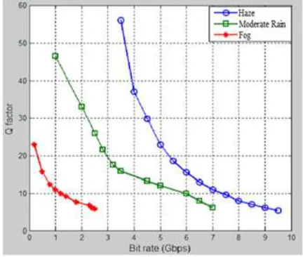
In 2017, Sujon Kumar Biswas, Pankaj Biswas, Jobaida Akhtar and Mohammad Istiaque Reja presented a paper entitled, “Estimation of Link Range and Bit Rate for 16 Channel WDM-FSO Considering Atmospheric Turbulence and Pointing Error Under Various Weather Conditions”, IEEE. In this paper
authors have analyzed WDM-FSO system in terms of bit rate. They have measured maximum acceptable bit rate maintaining the acceptable value of Bit Error Rate (BER) of 10-9 and Quality factor of 6 in an atmospheric turbulent channel with pointing error under various weather conditions like haze, moderate rain and foggy weather. It is found that using maximum allowable pointing error, the maximum attainable bit rate is 9 Gbps, 6.5 Gbps and 2.5 Gbps for haze, moderate rain and foggy weather respectively at a constant link range of 2.2 km for haze and moderate rain and 1.1 km for fog. Simulation results of this paper are as follows:
Fig-2: Literature result
4. PROPOSED WORK
IJIRT 144769
INTERNATIONAL JO URNAL OF INNOVATIVE RESEARCH IN TECHNOLOGY390
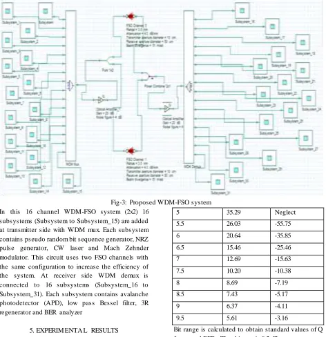
Fig-3: Proposed WDM-FSO system In this 16 channel WDM-FSO system (2x2) 16
subsystems (Subsystem to Subsystem_15) are added at transmitter side with WDM mux. Each subsystem contains pseudo random bit sequence generator, NRZ pulse generator, CW laser and Mach Zehnder modulator. This circuit uses two FSO channels with the same configuration to increase the efficiency of the system. At receiver side WDM demux is connected to 16 subsystems (Subsystem_16 to Subsystem_31). Each subsystem contains avalanche photodetector (APD), low pass Bessel filter, 3R regenerator and BER analyzer
5. EXPERIM ENTA L RESULTS
Proposed 16 channel WDM FSO system is simulated to determine the Q-factor and BER when link range is constant at different atmospheric conditions and different bit rate of communication.
Table 1 Simulation results for constant link range at haze climate
Link range = 2.2 Km, Attenuation = 4.3 dB/Km, Pointing error = 13 mrad
Bit rate (Gbps) Q-factor Log(BER)
4 71.69 Neglect
4.5 47.41 Neglect
5 35.29 Neglect
5.5 26.03 -55.75
6 20.64 -35.85
6.5 15.46 -25.46
7 12.69 -15.63
7.5 10.20 -10.38
8 8.69 -7.19
8.5 7.43 -5.17
9 6.37 -4.11
9.5 5.61 -3.16
Bit range is calculated to obtain standard values of Q factor and BER. That bit rate is 9.2 Gbps.
Table 2 Simulation results for constant link range at moderate rain climate
Link range = 2.2 Km, Attenuation = 9.64 dB/Km, Pointing error = 12.4 mrad
Bit rate (Gbps) Q-factor Log(BER)
2.5 44.67 Neglect
3 36.78 Neglect
3.5 33.45 -76.61
4 28.67 -67.33
© November 2018 | IJIRT | Volume 5 Issue 6 | ISSN: 2349-6002
IJIRT 147292
INTERNATIONAL JO URNAL OF INNOVATIVE RESEARCH IN TECHNOLOGY391
5 21.57 -43.71
5.5 18.35 -30.33
6 15.74 -18.79
6.5 13.52 -17.26
7 11.38 -10.89
7.5 9.43 -8.35
8 7.94 -6.27
8.5 6.75 -5.68
9 6.13 -4.19
9.5 5.72 -3.25
Bit range is calculated to obtain standard values of Q factor and BER. That bit rate is 9 Gbps.
Table 3 Simulation results for constant link range at fog climate
Link range = 1.1 Km, Attenuation = 43 dB/Km, Pointing error = 4 mrad
Bit rate (Gbps) Q-factor Log(BER)
1 17.36 -21.25
1.5 15.14 -18.47
2 12.59 -15.55
2.5 10.85 -15.06
3 9.87 -14.76
3.5 9.14 -12.85
4 8.76 -11.33
4.5 8.13 -10.28
5 7.81 -8.39
5.5 7.38 -6.94
6 6.82 -5.84
6.5 6.18 -4.76
7 5.69 -3.88
Bit range is calculated to obtain standard values of Q factor and BER. That bit rate is 6.6 Gbps.
Fig-4: Bit rate vs log (BER) for different climate conditions
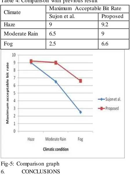
Table 4: Comparison with previous result
Climate Maximum Acceptable Bit Rate
Sujon et al. Proposed
Haze 9 9.2
Moderate Rain 6.5 9
Fog 2.5 6.6
Fig-5: Comparison graph
6. CONCLUSIONS
In this work three attenuation factors are considered such as 4.3 dB/Km for haze climate, 9.64 dB/Km for moderate rain climate and 43 dB/Km for fog climate. Proposed design of WDM FSO is simulated at all attenuation factors for different bit rate when link range is constant. The maximum attainable bit rate (at a link range of 2.2 km for haze and moderate rain and 1.1 km for fog) is 9.2 Gbps, 9 Gbps and 6.6 Gbps for the haze, moderate rain and foggy weather respectively.
REFERENCES
[1] Pei-Lin, C., Shenq-Tsong, C., Shuen-Te, J., Shu-Chuan, L., Han-Hsuan, L., Ho-Lin, T., Po-Hsuan, H., “Demonstration of 16 channels 10 Gb/s WDM free space transmission over 2.16 km”, Digest of the IEEE/LEOS Summer Topical Meetings 2008.
[2] Barry, J. R., “Wireless Infrared
IJIRT 147292
INTERNATIONAL JO URNAL OF INNOVATIVE RESEARCH IN TECHNOLOGY392
[3] Bloom, S., Korevaar, E., Schuster, J., Willebrand, H., “Understanding the performance of free-space optics”, J. Opt. Netw., 2003. [4] Richardson, D. J., Fini, J. M., Nelson, L. E.,
“Space-division multiplexing in optical fibres”, Nature Photonics, 2013.
[5] Rosas-Fernandez, J. B., Ingham, J. D., Penty, R. V., White, I. H., “18 Gchips/s electronic CDMA for low-cost optical access networks”, J. Lightwave Technol., 2009.
[6] Andrews, L. C., Phillips, R. L., “Laser Beam Propagation Through Random Media”, 2nd ed: SPIE Press, Bellingham, Washington; 2005. [7] Tyson, R. K., “Bit-error rate for free-space
adaptive optics laser communications”, J. Opt. Soc. of America 2002.
[8] Jin, X., Wang, X., Hsu, C. Y., “Design and implementation of mobile free space optical communication system”, IEEE Avionics, Fiber-Optics and Photonics Technol. Conf. 2008. [9] Doerr, C. R., Okamoto, K., “Advances in silica
planar lightwave circuits”, J. Lightw. Technol., 2006.
[10]Dutta, A. K., Dutta, N. K., Fujiwara, M., “WDM Technologies: Passive Optical Components: Passive Optical Components”, Academic press; 2003.
[11]Maru, K., Mizumoto, T., Uetsuka, H.,
“Demonstration of Flat-Passband
Multi/Demultiplexer Using Multi-Input Arrayed Waveguide Grating Combined With Cascaded Mach-Zehnder Interferometers”, J. Lightw. Technol., 2007.
[12]Banerjee, A., Park, Y., Clarke, F., Song, H., Yang, S., Kramer, G., Kim, K., “Wavelength-division-multiplexed passive optical network (WDM-PON) technologies for broadband access: a review”, J. Opt. Netw., 2005.
[13]Chang-Hee, L., Sorin, W. V., Byoung-Yoon, K., “Fiber to the Home Using a PON Infrastructure”, J. Lightw.Technol., 2006.
[14]Farhana Hossain, and ZeenatAfroze, “Eliminating the Effect of Fog Attenuation on FSO Link by Multiple TX/RX System with TravellingWave Semiconductor Optical Amplifier”, IEEE, 2013.
[15]JyotiSaxena, Neel Kamal and Nitin Thathai, “WDM based FSO System for Long Haul Communication”, International Journal of
Engineering Research and Technology (IJERT), 2015.
[16]Aditi and Preeti, “An Effort to Design a Power Efficient, Long Reach WDM-FSO System”, IEEE, 2014.
[17]Dhaval Shah and Dilip Kumar Kothari, “Optimization of 2.5 Gbps WDM-FSO link range under different rain conditions in Ahmedabad”, IEEE, 2014.
[18]Mazin Ali and A. Ali, “Performance analysis of terrestrial WDM-FSO Link under Different Weather Channel”, World Scientific News, 2016.
[19]Manpreet Kaur and Gurpreet Kaur, “Simulative Investigation of WDM-FSO Link under Different Atmospheric Conditions”, International Journal of Advanced Research in Computer Science, 2017.