Article
A Unified Reconfigurable CORDIC Processor for
Floating-Point Arithmetic
Linlin Fang 1, Bingyi Li 1, Yizhuang Xie 1,* and He Chen 1
1 Beijing Key Laboratory of Embedded Real-time Information Processing Technology, Beijing Institute of
Technology, Beijing 100081, China; [email protected] (L.F.); [email protected] (B.L.); [email protected] (Y.X.); [email protected] (H.C.)
* Correspondence: [email protected]; Tel.: +86-156-5279-7282
Abstract: This paper presents a unified reconfigurable coordinate rotation digital computer (CORDIC) processor for floating-point arithmetic. It can be configured to operate in multi-mode to achieve a variety of operations and replaces multiple single-mode CORDIC processors. A reconfigurable pipeline-parallel mixed architecture is proposed to adapt different operations, which maximizes the sharing of common hardware circuit and achieves the area-delay-efficiency. Compared with previous unified floating-point CORDIC processors, the consumption of hardware resources is greatly reduced. As a proof of concept, we apply it to 16384
16384 points target Synthetic Aperture Radar (SAR) imaging system, which is implemented on Xilinx XC7VX690T FPGA platform. The maximum relative error of each phase function between hardware and software computation and the corresponding SAR imaging result can meet the accuracy index requirements.Keywords: reconfigurable architecture; CORDIC; Field Programmable Gate Array(FPGA); SAR imaging
1. Introduction
The CORDIC algorithm involves a simple shift-and-add iterative procedure to perform several computing tasks. It can execute the rotation of a two-dimensional (2-D) vector in linear, circular, and hyperbolic coordinates systems [1]. Due to the simplicity of its hardware implementation, CORDIC has a wide range of applications in signal processing and image processing, such as QR decomposition [2], singular value decomposition [3], 3-D graphics [4] and robotics [5]. The hardware implementation of these applications requires more than one CORDIC processor operating in different modes and different trajectories.
Several unified CORDIC processors have been designed and implemented in previous research. However, previous researches mainly focus on performing fixed-point number arithmetic system based on circular and hyperbolic coordinate. None of the previous designs include linear coordinate system. Literature [6] adopts the traditional pipeline iteration, and just adds the selection signal for mode selection. A reconfigurable CORDIC processor based on scaling-free CORDIC algorithm is demonstrated in [7], which simplifies the iterative computation at the expense of low accuracy. A floating-point CORDIC co-processor is proposed in [8], but the hardware architecture of pre- and post- processing module is too complicated and consumes large resources.
In this paper, we propose a unified reconfigurable floating-point CORDIC processor, which can be operated in three coordinate systems using either rotation-mode or vectoring-mode to complete a variety of operations. The range of convergence (ROC) of algorithm is extended by domain conversion, and the software per-simulation method is used to optimal data width and iterative numbers. According to the dynamically configurable features of FPGA, we optimize the iterative module by designing a pipeline-parallel mixed architecture based on binary-to-bipolar recoding(BBR) [9] techniques, which maximizes the sharing of common hardware circuit in different
configurations. The proposed processor achieves high precision, less time latency as well as hardware-complexity of implementation.
To further validate the design, we establish the FPGA-based prototype and apply it to the calculation of three phase functions in chirp-scaling (CS) SAR imaging algorithm [10]. Compared with the simulation results of software, the relative error is less than 10-3. After imaging processing,
according to the quality assessment method as [11] described, the result is suitable for both vision and index requirements.
The rest of the article is organized as follows. In section 2, we review CORDIC algorithm. In Section 3, we deduce and simulate the ROC of the algorithm, and analysis the relationship of iterative numbers and data width. In section 4, we propose a unified reconfigurable CORDIC processor. Section 5 discusses the synthesis results of FPGA implementation and precision. Section 6 summarizes the main contributions of this work and concludes the paper.
2. Review of unified CORDIC algorithm
In 1971, Walther reformulated the CORDIC algorithm into a generalized and unified form which is suitable to perform rotations in circular, linear and hyperbolic coordinate systems [1]. It has laid a solid theoretical foundation for designing a unified CORDIC processor architecture. The generalized CORDIC is formulated as follows:
1
1
1
(Y 2 )
(X 2 ) , 0,1, 2,..., 1 i
i i i i
i
i i i i
i i i i
X X m
Y Y i N
Z Z
, (1)
For m=1,0 or -1, and tan 1
2i i ,2i ortanh1
2i , the algorithm given by (1) works in circular, linear or hyperbolic coordinate (CC, LC or HC) system, respectively. i
1,1 is the direction of micro-rotation. In the rotation mode (RM), coordinate Z is driven to zero, i sign Z
i ,and in the vectoring mode (VM), Y is driven to zero, i sign Y
i .The value of scaling factor is
1 21
2
0
1 2
N
i m
i
K m
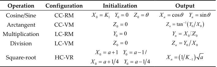
, (2)The proposed reconfigurable CORDIC processor in this paper is aimed at the calculation of phase functions in chirp-scaling algorithm. Table I shows these elementary functions and operations which can be implemented by CORDIC. The pre- and post-processing step are necessary to perform the operation.
Table 1. Computations using CORDIC algorithm in different configurations
Operation Configuration Initialization Output Cosine/Sine CC-RM X0K1 Y00 Z0 Xn cos Ynsin
Arctangent CC-VM Z00
1 0 0 tan n
Z Y X
Multiplication LC-RM Y0 0 YnX Z0 0
Division LC-VM Z00 ZnY X0 0
Square-root HC-VR X0 a 1 Y0 a 1/
0 1 4
X a Y0 a 1 4
1 1
n3. Software Pre-analysis of ROC and Iterative Numbers
3.1. Analysis of ROC
The ROC is an important aspect in the design of the CORDIC processor and determines the scope of the algorithm. We analyze the ROC based on theoretical deduction and verify it based on MATLAB simulation. The ROC of five types of floating-point operation is shown in Figure 1. Multiplication
According to the iterative formula of Z-path, after N iterations, the formula can be derived as follows:
1 2 3
1 1 12 22 32 2
N
N N
Z Z
, (3)
Since212223 2N 1 2N 1, initial value need to satisfy
1 1
Z to ensure that
1
N
Z converges to 0 after N iterations.
Division
According to iterative formula of Y-path, after N iterations, the formula can be derived as follows:
1 2 3
1 1 1 12 22 32 2
N
N N
Y Y X
, (4)
Hence, initial value need to satisfy Y X1 1 1 to ensure that YN1 converges to 0 after N
iterations.
Trigonometric functions
According to [12], the ROC of sine and cosine functions is Z 99.827 ,as well as
1
tan Y X 99.827for arctangent function, they can’t cover the entire cycle. Therefore, it is necessary to expand the range with some mathematical relationships.
Square-root
In this paper, we discuss two kinds of transformation solutions for the input coordinates of the initial vector:
1st solution:
0 1, Y0 1
X X X
2nd solution:
0 1 / 4, Y0 1/ 4
X X X
Where, X represents the operand.
Based on software simulation, the relative error graphs of five types operation are shown in Figure 1. The relative error Erelativecan be represented as:
r
E results arithmetic elative
arithmetic
R R
R
, (5)
Where, Rresultsis software(MATLAB) simulation results of CORDIC algorithm, Rarithmeticis the reference results provided by the MATLAB built-in arithmetic function in single float point precision.
For square-root, the ROC of 1st and 2nd solution is (0.12,9.36) and (0.03,2.34) respectively. For
fixed-point arithmetic, 1st solution is only operated in the integer part of the data, therefore, it will
produce less carry and make the operation simpler. Besides, compared to 2nd solution, the ROC is
0 0.2 0.4 0.6 0.8 1 1.2 1.4 1.6 1.8 2 10-10 10-8 10-6 10-4 10-2 100
The range of sampling points
R e la tiv e er ro r
0 0.2 0.4 0.6 0.8 1 1.2 1.4 1.6 1.8 2 10-10 10-8 10-6 10-4 10-2 100
The range of sampling points
R e la tiv e er ro r
(a) Multiplication (b) Division
-150 -100 -50 0 50 100 150
10-10 10-8 10-6 10-4 10-2 100
The range of sampling points
R e la tiv e er ro r
-150 -100 -50 0 50 100 150
10-10
10-5
100
105
The range of sampling points
R e la tiv e e rr o r
0 2 4 6 8 10
10-10 10-8 10-6 10-4 10-2 100
The range of sampling points
R e la tiv e er ro r 1st solution 2st solution
(c) Sine/Cosine (d) Arctangent (e) square-root
Figure 1. The ROC of different floating-point operation
3.2. Analysis of optimum iterative numbers and data width
There is a need for trade-off between hardware-cost, latency and numerical accuracy subject to the application. The accuracy of the CORDIC algorithm is related to the data bit width b and iterative numbers N. The total quantization error consists of two parts: approximate error and rounding error.
According to [13], the approximate error EA and rounding error ER can be described as:
1
2 N 0 A
E v , (6)
1 1 1 0.5 1 0 1 2 1 N Nj i j b R N i k i E k i
, (7)Where,
1 20
1 2
N
i i
k i m
. Thus, the total quantification error Etotal is:total A R
E E E , (8)
Based on the above theoretical derivation, we introduce the simulation-based method to confirm optimal number of iterations and data width, as shown in Figure 2. In order to satisfy
6 10 total
E , the number of iteration is set to 24, the data width b is set to 23, the word-length of the
3 of 12
14 16 18 20 22 24 26 28 10-8
10-7 10-6 10-5 10-4 10-3 10-2
data width b
qu
a
nt
ifi
ca
tio
n
er
ro
r
N=16 N=18 N=20 N=22 N=24 N=26
Figure 2. Relationship between iterative number N and data width b
4. Proposed reconfigurable CORDIC processor
The proposed reconfigurable floating-point CORDIC processor design is shown in Figure 3. By adding selectors, common circuits in different modes can be maximized for reuse. We set 2-bit signal T1&T0 valued as 00,01 or 10 to represent circular, linear or hyperbolic coordinate system respectively, and 1-bit signal P equals to 0 or 1 to represent rotation or vector mode respectively.
Pre-processing
Reconfigurable CORDIC Rotation Unit
Post-processing
Input data
T1&T0&P
X_Path_in
Y_Path_in Z_Path_in
X_Path_out
Y_Path_out Z_Path_out
Result
Figure 3. Proposed reconfigurable CORDIC processor
4.1. Pre-processing module
This module mainly completes the conversion from floating-point to fixed-point numbers and expands the ROC. In this paper, we adopt the IEEE-754 standard single precision floating-point data format [14]. The input data can be represented as:
1SX 2EXBias 1.M X
X
1SY 2EYBias 1.M
Y
Y
1SZ 2EZBias 1.M
Z
Z
Where, Bias127, the data consists of 1-bit for sign(S), 8-bit for exponent(E), and rest of 23-bit for mantissa(M) or fractional part. Figure 4 shows the hardware structure of pre-processing module. Depending on the operation selected by user, appropriate data path is picked up by signal T1&T0&P.
The outputs of the pre-processing module, i.e. X0, Y0, and Z0, in different data paths are shown in
Table 2.
Table 2. The selection of different data-path
T1&T0&P Operation X0 Y0 Z0 Exp
000 Sine/Cosine MX MY NZ /
001 Arctangent NX NY MZ /
010 Multiplication MX MY MZ EX+EZ-127
011 Division MX MY/2 MZ EY-EX+127
-EX
SX
Shifter MX
-EY
SY
Shifter MY
Code
+
DX DY
M
U
X
DX
-DX
DY
-DY
NX
NY
-EZ
Shifter MZ
SZ
MUX 4 3
4 3 4
4
Comparator
Code 02
MUX
+
+/-NZ
DZ
8'h7F 8'h7F 8'h7F
+ 24'h800000
->>1
MUX1 MUX2 MUX3 T1&T0&P
X0 Y0 Z0
MUX
+ +/-+
+/->>1
MUX 8'h7F
Exp
Figure 4. Hardware structure of pre-processing module
Trigonometric functions operation
The mantissa is shifted according to the result of E minus 127, and it is converted into fixed-point form of 1-bit sign, 1-bit integer and 23-bit decimal part. In this module, the fixed-point numbers are expressed as DX, DY and DZ. Then, we use the method of mathematical transformation
to map the data of entire circumference to the range of which can be covered by CORDIC algorithm. We divide the entire circumference into five intervals and encode it. Through the mapping relations in Table 3, the input phase or vector in interval B, C, D or E can be transformed into interval A. NX,
NY, NZ are the output values after operation.
Table 3. Mapping relations of different quadrants
Domain Range of the
target angle S2&S1&S0 Sine/Cosine(Z) Arctangent(X,Y)
A
4, 4
000 Z X'X Y, 'YB
4,3 4
001 Z 2 X' Y Y, 'XC
3 4,
010 Z X' X Y, ' YD
, 3 4
011 Z X' X Y, ' YE
3 4, 4
100 Z 2 X'Y Y, ' X Multiplication and division operation
The mantissa is expressed as fixed-point number which includes 1-bit sign, 1-bit integer and 23-bit decimal part as the input of CORDIC rotation unit. For multiplication, EY=EX+EZ-127. For
division, EZ=EY-EX+127, in order to ensure |Y/X|<1, we add a right shifter in Y data path.
Square-root operation
Determining the parity of exponent firstly, the exponent is divided by 2 directly, according to the exponent, the mantissa part is expressed as the corresponding fixed-point number format. The initial value of X- and Y-path is MX plus 1, MY minus 1 respectively, where, MX equal to MY.
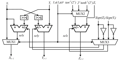
4.2. Design of reconfigurable CORDIC rotation module
4.2.1. Rotation unit A
5 of 12
>>i >>i
+ +/- +
MUX1
MUX2 Zi
tan-1(2-i
) 2-itanh-1(2-i)
Xi Yi
Xi+1 Yi+1 Zi+1
selx sely selz
T1&T0&P
+/- +/- +
MUX3 Sign(Zi) Sign(Yi)
Figure 5. Architecture of reconfigurable rotation unit A (single-layer)
Table 4. The selection of data path
T1&T0&P
MUX1 MUX2 MUX3
X-Path i selx sely selz
000 1
2
i
i i i
x x selx y
i tan1
2i
~sign Z i sign Z i ~sign Z i
001 xi1 xi selx y
i2i
i tan1
2i
sign Y i ~sign Y i sign Y i
010 xi1xi i 2i
/ sign Z i ~sign Z i
011 xi1xi i 2i
/ ~sign Y i sign Y i
101 1
2
i
i i i
x x selx y
i tanh1
2i
~sign Y i ~sign Y i sign Y i
4.2.2. Rotation unit B
Rotation unit B is used to implement parallel structure. Based on binary-to-bipolar recoding (BBR) technique, in rotation mode, rotation directions ican be predicted by the binary value of the initial input angle in parallel. Parallel processing method unfold the micro-rotation directly. Thus, the rotation of X- and Y-path can be executed concurrently. The iterations from the (N/2+1)th to the (N+1)th can be simplified as follows:
1 / 2 1 / 2 1 / 2 1
1 / 2 1 / 2 1 / 2 1
2
2 N
i
N N N i
i N N
i
N N N i
i N
X X Y
Y Y X
, (9)13
14 15 22 23 24
Figure 6. Architecture of reconfigurable rotation unit B
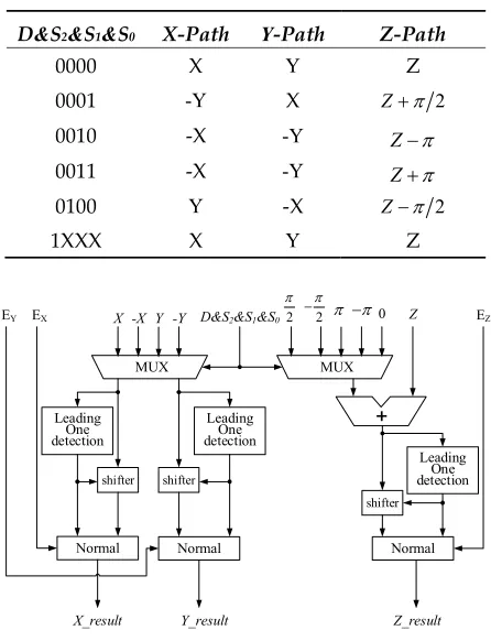
4.3. Post-processing module
This module implements the quadrant recovery of trigonometric functions and fixed-point to float-point conversion. We set 1-bit signalD T 1T0, D0represents trigonometric operation andD1 represents other three operations. The recovery of quadrant is accomplished according to code signal S2&S1&S0 acquired in pre-processing module. As shown in Table 5, proper data are
picked up in three paths. Then, according to leading ‘1’ location of fixed-point data except sign bit, the exponent part is normalized and mantissa part is determined, finally, they are spliced together as the outputs, the fixed-point number is converted into floating-point number. The final output results are represented as X_result, Y_result, Z_result, respectively. The hardware structure is shown in Figure 7.
Table 5. Data selection of different path
D&S2&S1&S0 X-Path Y-Path Z-Path
0000 X Y Z
0001 -Y X Z 2
0010 -X -Y Z
0011 -X -Y Z
0100 Y -X Z 2
1XXX X Y Z
MUX X -X Y -Y
MUX 0 D&S2&S1&S0
shifter
+ Z
shifter
shifter
Normal Normal Normal
Leading One detection
Leading One detection
Leading One detection EX
EY EZ
X_result Y_result Z_result
2
2
7 of 12 4.4. Proposed unified reconfigurable CORDIC architecture
In rotation module, according to the dynamically configurable features of FPGA, we propose a pipeline-parallel mixed architecture, 1st to 12th iterative units are same in different modes, where all of them adopt rotation unit A to implement in pipeline. The differences are mainly reflected in the 13th to 24th units, as shown in Table 6. Module II is used to complete the compensation of scaling factor K in square root operation. The unified reconfigurable architecture is shown in Figure 8.
Table 6. Module Selection
Operation Module Selection of 13-24 layers Result output
Cosine/Sine Module III X_result/Y_result
Arctangent Module I Z_result
Square Root Module II X_result
Multiplication Module III Y_result
Division Module I Z_result
Pre-process X_in Y_in Z_in
Rotation unit A(1-12)
Rotation
unit A(12-24) unit B(12-24)Rotation
Post-process Scaling Circuit X0 Y0 Z0
X12 Y12 Z12 X12 Y12 Z12
X12
Y12 Z12
X_out Y_out Z_out
X_result Y_result Z_result T1&T0&P
I
II
III
MUX
Figure 8. The unified reconfigurable CORDIC processor architecture
5. FPGA implementation results and comparison
5.1.Synthesis results
The reconfigurable CORDIC processor is coded in VHDL and synthesized using the Xilinx ISE 14.7 development tool. In order to achieve a fair comparison with other references, we choose
Virtex5 XC5VFX130T FPGA as platform for implementation. The input data of processor uses single precision floating-point numbers, the X, Y and Z path in CORDIC rotation unit use 25-bit fixed-point numbers. Table 7 shows the FPGA resource occupation and a comparison with several previous works. We use the average relative error(ARE) in different modes for accuracy analysis, the relative error is expressed by formula (5), where, Rresults is the hardware simulation results of our designed processor. We can see, in the condition of same ARE,the LUT and register consumption are less than that of the related design described in [15], [17] and [8]. Compared with references [16], the proposed design can achieve higher frequency.
route, the max working frequency is lower than literature [6], but it is higher than [7] due to a simple hardware architecture design. When the data format is 25-bit fixed point, the iterative number is 24, the resource consumption is slightly larger, however, it can achieve higher precision. Therefore, the proposed processor can make a good compromise in resources, accuracy and speed.
Table 7. Comparison of resources with previous floating-point CORDIC processor
Method Year LUTs Registers Frequency
(MHz) ARE
[15] 2015 4361 410 125.00
10-6
[16] 2011 2151 1535 133.80
[17] 2010 3538 / 85.9
[8] 2008 5412 5130 217.24
proposed 2018 3528 3286 238.65
Table 8. Resources comparison of rotation unit module
Data Format
(fixed-point) Method Year LUTs Registers
Frequency (MHz) ARE
16-bits [6] 2014 1460 898 323.76 10-4
[7] 2016 2161 369 142.14 10-3
16-bits proposed 2018 1458 932 245.35 10-4
25-bits proposed 2018 2169 1687 243.78 10-6
5.2. Precision analysis
To verify the precision of our design, we apply the proposed processor to SAR imaging system, test scenario is 16384
16384 points target scene, the SAR imaging system is implemented in Virtex7 XC7VX690T FPGA. Due to the large data granularity, we adopt region-constant phase multipliers [18], the phase functions in the chirp scaling imaging algorithm are extracted by 8:1, the number of each phase function is 2048. We compare the three phase functions’ hardware simulation resultsresults
R with the corresponding MATLAB simulation results Rarithmetic , on the basis of formula (5), calculating the maximum relative error for each factor line, as shown in Figure 9. We can see the value is between 10-3 and 10-5, which is acceptable in high-resolution imaging. Generally, the
precision of phase function mainly influences the imaging quality. Thus, we take advantage of the image quality assessment methodology described in [11] with integrity SAR imaging procedure to experiment the proposed phase function result.
500 1000 1500 2000 10-6
10-5 10-4 10-3 10-2
The numbers of 1st phase function
R
el
at
iv
e
er
ro
r
Relative error of 1st phase function
500 1000 1500 2000 10-6
10-5 10-4 10-3 10-2
The numbers of 2nd phase function
R
e
la
tiv
e
e
rr
or
Relative error of 2nd phase function
500 1000 1500 2000 10-6
10-5 10-4 10-3 10-2
The numbers of 3rd phase function
R
el
at
iv
e
er
ro
r
Relative error of 3rd phase function
(a) 1st phase function errors (b) 2nd phase function errors (c) 3rd phase function errors
Figure 9. The maximum relative errors of three phase functions
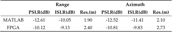
9 of 12 integrated side-lobe ratio (ISLR) and resolution(RES) are commonly adopted to evaluate the imaging quality [11]. We can see that the imaging quality is good, approximate 2-dB degrade of PSLR and ISLR meet the requirements of the engineering indicators.
(a) MATLAB imaging (b) FPGA imaging
Figure 10. Point target imaging result
Table 9. Point target evaluation result
Range Azimuth
PSLR(dB) ISLR(dB) Res.(m) PSLR(dB) ISLR(dB) Res.(m)
MATLAB -12.61 -10.05 1.90 -12.52 -11.41 2.10
FPGA -10.12 -9.13 2.40 -10.81 -9.83 2.73
6. Conclusions
In this paper, we design a unified reconfigurable floating-point CORDIC processor, which can be operated in different modes and calculate varieties of floating-point arithmetic. It replaces multiple single-mode processors and reduces the numbers of processors needed in the operation. Besides, the ROC is extended and multiple operations are integrated. A reconfigurable pipeline-parallel mixed architecture is proposed in rotation module to adapt different floating-point operations. Compared to traditional CORDIC processor, it greatly saves hardware resources and has high accuracy, with an acceptable maximum working frequency. Besides, the relative error of each phase function line between hardware and software computation is acceptable, and the corresponding SAR imaging result is good.
Funding: This work was supported by the National Natural Science Foundation of China under Grant 91438203, the Chang Jiang Scholars Program under Grant T2012122 and the Hundred Leading Talent Project of Beijing Science and Technology under Grant Z141101001514005.
Author Contributions: Linlin Fang and Bingyi Li conceived and developed the ideas behind the research. Linlin Fang performed the theoretical deviations, experiments, and simulations. Linlin Fang wrote the paper, Yizhuang Xie provided guidance and key suggestions. He Chen supervised the research, and revised the paper.
Conflicts of Interest: The authors declare no conflicts of interest.
References
1. Walther J S. A unified algorithm for elementary functions. Spring Joint Computer Conference. ACM, May
18-20, 1971,Vol.38, pp.379-385 (DOI: 10.1145/1478786.1478840).
2. Lightbody G, Woods R, Walke R. Design of a parameterizable silicon intellectual property core for
QR-based RLS filtering. Very Large Scale Integration Systems IEEE Transactions on, 2003, 11(4), pp.659-678
(DOI: 10.1109/TVLSI.2003.816142).
3. Cavallaro J R, Luk F T. CORDIC arithmetic for an SVD processor. Journal of Parallel & Distributed
Computing, 1988, 5(3), pp.113-120(DOI: 10.1109/ARITH.1987.6158686).
4. Lang T, Antelo E. High-Throughput CORDIC-Based Geometry Operations for 3D Computer Graphics.
IEEE Transactions on Computers, 2005, 54(3), pp.347-361(DOI: 10.1109/TC.2005.53).
5. Kameyama M, Amada T, Higuchi T. Highly parallel collision detection processor for intelligent robots.
6. Aggarwal S, Meher P K. Reconfigurable CORDIC architectures for multi-mode and multi-trajectory operations. IEEE International Symposium on Circuits and Systems. IEEE, 2014, pp.2490-2494(DOI: 10.1109/ISCAS.2014.6865678).
7. Aggarwal S, Meher P K, Khare K. Concept, Design, and Implementation of Reconfigurable CORDIC. IEEE
Transactions on Very Large Scale Integration Systems, 2016, 24(4), pp.1588-1592(DOI: 10.1109/TVLSI.2015.2445855).
8. Zhou J, Dong Y, Dou Y, et al. Dynamic Configurable Floating-Point FFT Pipelines and Hybrid-Mode
CORDIC on FPGA. 2008(DOI: 10.1109/ICESS.2008.95).
9. Juang T B, Hsiao S F, Tsai M Y. Para-CORDIC: parallel CORDIC rotation algorithm. Circuits & Systems I
Regular Papers IEEE Transactions on, 2004, 51(8), pp.1515-1524(DOI: 10.1109/TCSI.2004.832734).
10. Runge H, Bamler R. A Novel High Precision SAR Focussing Algorithm Based On Chirp Scaling.
Geoscience and Remote Sensing Symposium, IGARSS '92. International. IEEE, 1992, pp.372-375(DOI: 10.1109/IGARSS.1992.576715).
11. Zhang H, Li Y, Su Y. SAR image quality assessment using coherent correlation function. 2012(DOI:
10.1109/CISP.2012.6469650).
12. Meher P K, Valls J, Juang T B, et al. 50 Years of CORDIC: Algorithms, Architectures, and Applications.
IEEE Transactions on Circuits & Systems I Regular Papers, 2009, 56(9), pp.1893-1907(DOI: 10.1109/TCSI.2009.2025803).
13. Hu Y H. The quantization effects of the CORDIC algorithm. Signal Processing IEEE Transactions on, 1992,
40(4), pp.834-844(DOI: 10.1109/78.127956).
14. IEEE. “IEEE Standard for Floating-Point Arithmetic,” IEEE Std 754-2008, 2008, pp.1-82(DOI:
10.1109/IEEESTD.2008.4610935).
15. Mack J, Bellestri S, Llamocca D. Floating point CORDIC-based architecture for powering computation.
International Conference on Reconfigurable Computing and Fpgas. IEEE, 2015 (DOI: 10.1109/ReConFig.2015.7393311).
16. Surapong P, Glesner M. Pipelined Floating-Point Architecture for a Phase and Magnitude Detector Based
on CORDIC. International Conference on Field Programmable Logic and Applications. IEEE Computer Society, 2011, pp.382-384(DOI: 10.1109/FPL.2011.74).
17. Munoz D M, Sanchez D F, Llanos C H, et al. FPGA based floating-point library for CORDIC algorithms.
Programmable Logic Conference. IEEE, 2010, pp.55-60(DOI: 10.1109/SPL.2010.5483002).
18. Wen Y, He C, Xie Y Z, et al. A New Chirp Scaling Algorithm Using Region-Constant Phase Multipliers.