THERMAL PERFORMANCE OF A TWO
PHASE CLOSED THERMOSYPHON
USING AQUEOUS SOLUTION
M. KARTHIKEYAN1, S. VAIDYANATHAN2, B. SIVARAMAN3
1Lecturer (Senior Scale) in Mechanical Engineering, Annamalai University, Annamalai Nagar – 608002,
TamilNadu, India. Ph: +91 98653 26046
2Reader in Mechanical Engineering, Annamalai University, Annamalai Nagar – 608002, Tamil Nadu, India.
ABSTRACT
The thermal performance of an inclined two phase closed thermosyphon with different working fluid has been investigated experimentally in this paper. Distilled water and an aqueous solution that has a positive gradient of surface tension with temperature are used as the working fluid. A copper thermosyphon with a length of 1000 mm long, an inner diameter of 17 mm and an outer diameter of 19 mm was employed. Each thermosyphon was charged with 60% of the working fluid and was tested with an evaporator length of 400 mm and condenser length of 450 mm. The thermosyphon was tested for various inclinations of 45○, 60○ and 90○ to the horizontal. Flow rate of 0.08Kg/min, 0.1 Kg/min and 0.12 Kg/min and heat input of 40 W, 60 W and 80 W were taken as input parameters. The thermal performance of aqueous solution charged two phase closed thermosyphon was out performed the distilled water in both heat transfer and temperature distribution.
Keywords: Two phase closed thermosyphon, heat transfer coefficient, aqueous solution
1. INTRODUCTION
Two phase closed thermosyphon also known as wickless heat pipes is an effective heat transfer device. It is a vertically oriented wickless heat pipe with a liquid pool at the bottom. It consists of an evacuated closed pipe filled with a certain amount of suitable working fluid. The two phase closed thermosyphon is divided into three main sections namely the evaporator section, adiabatic section and condenser section. When heat is added on the evaporator section, the working fluid inside the pipe vapourize and carries heat from the heat source to the condenser section, where heat is transferred to the heat sink. The condensate working fluid returns to the evaporator section by gravity force only. Hence, the condenser section of the pipe must be located above the evaporator section.
Due to the large latent heat transfer associated with the phase change processes, a large quantity of heat can be transferred from the evaporator section to the condenser section with a relatively small temperature difference. The important advantage of a two phase closed thermosyphon is that its critical heat flux is 1.2 – 1.5 times greater than the heat pipe [6].
thermosyphons and concluded that the inclination angle of a thermosyphon has a notable influence on the condensation coefficient and the optimum inclination angle varies from 20o to 50o with filling ratio.
Zhang [13] promoted the use of working fluids for heat pipe systems like dilute alcohol solutions (range between 0.0005 and 0.008 moles per litre) which exhibit a non-linear dependence of the surface tension with temperature and a positive gradient with increasing temperature in a suitable range of temperatures and concentrations. At low concentration, the aqueous solutions behave like positive binary mixtures [1].
2. EXPERIMENTAL SETUP
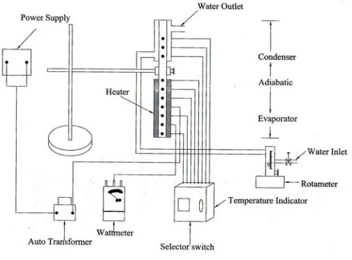
To study the thermal performance of a two phase closed thermosyphon, an experimental setup has been designed. The schematic of the experimental test is shown in the Figure 1. The parameters and the ranges of two phase closed thermosyphon and limitation of thermosyphon are tabulated in Table 1 and 2 respectively.
Figure 1. The experimental set up
The thermosyphon under the study has 1000 mm long of 19 mm outer diameter and 17 mm inner diameter made of copper tube. The length of the evaporator section is 400 mm, adiabatic section is 150 mm and condenser section is 450 mm. Distilled water and aqueous solution of n-Butanol (1x10⁻³ moles/litre) were used as the working fluid. Five thermocouples are provided in the thermosyphon to measure the vapour temperature, evaporator temperature, one thermocouple is provided to measure adiabatic temperature, three thermocouples are provided to measure condenser temperature and two thermocouples are provided to measure water inlet temperature and water outlet temperature. Copper constantan thermocouples (T Type) are used to measure the temperature. The flow rate of cooling water was regulated by a rotameter. Electric heater which supplies heat respect to the evaporator section was made of nickel-chrome wire with a power of 1000 W. Thermocouples were connected to the digital temperature indicator to measure the corresponding temperatures. Auto transformer was used to vary the heat input.
Before charging the pipe, it was cleaned thoroughly to remove the grease or oil from the inner surface. A vacuum pump was used to eliminate any non condensable gases from the thermosyphon. Finally, the pipe was charged with the working fluid to make it ready for the experiment. A series of experiments were performed for inclination angle of 45○, 60○ and 90○with flow rate of 0.08 Kg/min, 0.1 Kg/min and 0.12 Kg/min and heat input of
Table 1: Parameters and the ranges of thermosyphon
Parameters Range
Inner diameter of the pipe 17 mm
Outer diameter of the pipe 19 mm
Total length of the pipe 1000 mm
Length of evaporator section 400 mm
Length of adiabatic section 150 mm
Length of condenser section 450 mm
Working fluid Distilled water, aqueous solution
Inclination angle 45○, 60○, 90○
Charging ratio 60%
Heat input 40 W, 60 W, 80 W
Table 2: Limitation of thermosyphon
Sonic Limit 46773.68 W
Boiling Limit 13241.48 W
Counter – current flow Limit 2516.08 W
3. RESULTS AND DISCUSSION
3.1 Temperature distribution along the thermosyphon
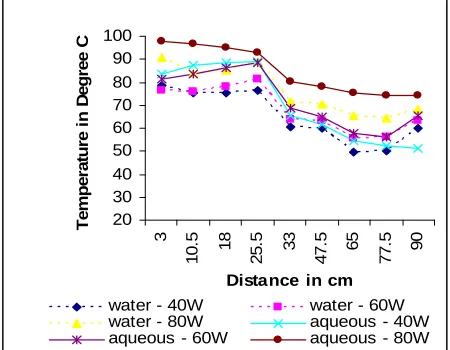
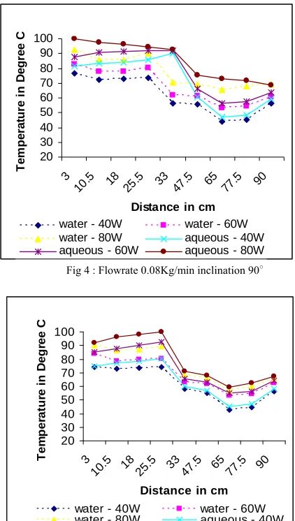
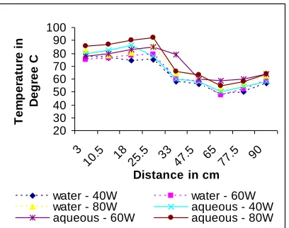
Fig. 2 to 10 shows distance Vs surface temperature along the thermosyphon. When heat input increases, the surface temperature of distilled water and aqueous solution used in the thermosyphon increases. The surface temperature of thermosyphon with aqueous solution is higher than the distilled water.
3.2 Effect of thermosyphon efficiency
Fig 11 to 13 shows the heat input Vs efficiency of thermosyphon for various heat input and flow rates for both distilled water and aqueous solution. The efficiency of thermosyphon gives better results for aqueous solution than the distilled water for all inclinations, heat input and flow rates. For vertical position of thermosyphon, the efficiency is higher than the other inclination. The lower inclination reduces the efficiency due to the obstruction of vapour with condensate return from the condenser. The efficiency is higher for 40 W heat input than the 60 W and 80 W heat inputs.
20 30 40 50 60 70 80 90 100 110
3
10.5 18 25.5 33 47.5 65 77.5 90
Distance in cm
T
em
p
er
atu
re i
n
D
eg
ree C
water - 40W water - 60W water - 80W aqueous - 40W aqueous - 60W aqueous - 80W
Fig 2 : Flowrate 0.08Kg/min inclination 45○
20 30 40 50 60 70 80 90 100
3
10
.5 18
25
.5 33
47
.5 65
77
.5 90
Distance in cm
T
em
p
er
at
u
re i
n
D
eg
ree
C
water - 40W water - 60W
water - 80W aqueous - 40W
aqueous - 60W aqueous - 80W
20 30 40 50 60 70 80 90 100 3
10.5 18 25.5 33 47.5 65 77.5 90
Distance in cm
T em p er atu re i n D eg ree C
water - 40W water - 60W
water - 80W aqueous - 40W
aqueous - 60W aqueous - 80W
Fig 4 : Flowrate 0.08Kg/min inclination 90○
20 30 40 50 60 70 80 90 100 3 10. 5 18
25.5 33 47.
5 65
77.5 90
Distance in cm
T em p er at u re in D eg ree C
water - 40W water - 60W
water - 80W aqueous - 40W
aqueous - 60W aqueous - 80W
Fig 5 : Flowrate 0.1Kg/min inclination 45○
20 30 40 50 60 70 80 90 100 3
10.5 18 25.5 33 47.5 6577.5 90
Distance in cm
T e m p er a tu re i n D eg ree C
water - 40W water - 60W
water - 80W aqueous - 40W
aqueous - 60W aqueous - 80W
Fig 6 : Flowrate 0.1Kg/min inclination 60○
20 30 40 50 60 70 80 90 100 3 10. 5 18 25. 5 33 47. 5 65 77. 5 90
Distance in cm
T e m p er at u re i n D eg re e C
water - 40W water - 60W
water - 80W aqueous - 40W
aqueous - 60W aqueous - 80W
Fig 7 : Flowrate 0.1Kg/min inclination 90○
20 30 40 50 60 70 80 90 100 3 10. 5 18 25. 5 33 47. 5 65 77. 5 90
Distance in cm
T em p er atu re i n D e g ree C
water - 40W water - 60W
water - 80W aqueous - 40W
aqueous - 60W aqueous - 80W
Fig 8 : Flowrate 0.12Kg/min inclination 45○
20 30 40 50 60 70 80 90 100 3 10. 5 18 25. 5 33 47. 5 65
77.5 90
Distance in cm
T e m p erat u re i n D eg ree C
water - 40W water - 60W
water - 80W aqueous - 40W
aqueous - 60W aqueous - 80W
20 30 40 50 60 70 80 90 100
3 10.
5 18
25.5 33 47.
5 65
77.5 90
Distance in cm
T
e
m
p
er
a
tu
re in
De
g
re
e
C
water - 40W water - 60W
water - 80W aqueous - 40W
aqueous - 60W aqueous - 80W
Fig 10 : Flowrate 0.12Kg/min inclination 90○
0 20 40 60 80 100
40 60 80
Heat input in Watt
E
ffi
ci
en
cy %
w ater 0.08Kg/min aqueous 0.08Kg/min w ater 0.1Kg/min aqueous 0.1Kg/min w ater 0.12Kg/min aqueous 0.12Kg/min
Fig11 : Efficiency for 45o inclination
0 20 40 60 80 100
40 60 80
Heat input in Watt
E
ff
ic
ien
cy %
water 0.08Kg/min aqueous 0.08Kg/min water 0.1Kg/min aqueous 0.1Kg/min water 0.12Kg/min aqueous 0.12Kg/min
Fig 12 : Efficiency for 60o inclination
0 20 40 60 80 100 120
40 60 80
Heat input in Watt
E
ffi
ci
en
cy
%
water 0.08Kg/min aqueous 0.08Kg/min
water 0.1Kg/min aqueous 0.1Kg/min
water 0.12Kg/min aqueous 0.12Kg/min
Fig 13 : Efficiency for 90o inclination
4. CONCLUSION
The effect of various flow rate, various heat input and inclination angle for both distilled water and aqueous solution on thermal performance of two phase closed thermosyphon has been investigated under normal operating conditions experimentally. Based on the results, the thermosyphon charged with aqueous solution has the maximum thermal performance than compared to thermosyphon charged with distilled water.
5. REFERENCES
1. Abe Y, “About self rewetting fluids – possibility as a new working fluid”, Thermal Science Engg 8(4), (2003).
2. Akbarzadeh A, Johnson P, Nguyen T, Mochizuki M, Mashiko M, Sauciuc I, Kusaba S and Suzuki H, “Formulation and Analysis of the heat pipe turbine for production of power from renewable sources”, Applied thermal Engineering, vo.21, pp. 1551-1563, (2001).
3. Amornkitbamrung M, Wangnippanto S and Kiatsirirote T, Performance studies on evaporation and condensation of a thermosyphon heat pipe, Proc 6th ASEAN Conference of Energy Technology, 28-29 August, Bangkok, Thailand, pp 27-34, (1995).
4. Dunn P D, Reay D A, “Heat pipes”, Fourth Edition, Pergamon Press, 1994 5. Faghri A, “Heat pipe science and Technology”, Taylor and Francis, London, 1995
6. Imura H., Sasaguchi K., and Kozai H., “Critical Heat flux in a closed two phase thermosyphon”, Int. J. of heat and Mass Transfer, vo.26, no.8, pp.1181-1188, (1983).
7. Negishi K and Sawada T, Heat transfer performance of an inclined two phase closed thermosyphon, Int. Journal of Heat and Mass Transfer, vol 26, no.8, pp. 1207-1213, (1983).
8. Payakaruk T, Terdtoon P and Ritthidech S, Correlations to predict heat transfer characteristics of an inclined closed thermosyphon at normal operating conditions, Applied Thermal Engineering, vol20, pp 781-790, (2000).
9. Peterson G P, “An Introduction to heat pipe”, Wiley and Sons, 1994
10. Terdtoon P, Ritthidech S and Shiraishi M, Effect of aspect ratio and bond number on an inclined closed two phase thermosyphon at normal operating condition, Proc 5th International Heat pipe symposium, 17-20 November, Melbourne, Australia, pp 261-266, (1996).