Method of Mesh Fabric Defect Inspection Based on
Machine Vision
Guodong Sun, PhD, Huan Li, Xin Dai, Daxing Zhao, PhD, Wei Feng
Hubei University of Technology, Wuhan, Hubei Province CHINA
Correspondence to:
Guodong Sun email: [email protected]
ABSTRACT
An appearance defect online inspection system of mesh fabric has been developed based on machine vision. The mean filter method is adopted to eliminate noise. An adaptive threshold method based on brightness is presented to eliminate the effects of uneven illumination and separate the foreground and background. By analyzing the texture characteristics and defect features of mesh fabric, the mesh fabric defect identification method based on texture features is proposed. The results have shown when the online inspection speed reaches 60m/min, the defect recognition rate can reach 95% or more and the online inspection system can meet the automation requirements of enterprises quite well.
Keywords: Machine vision, Mesh fabric, Defect inspection, Texture feature.
INTRODUCTION
Machine vision refers to using visual technology instead of the human eye to acquire information for computers, using software systems instead of the human brain to analyze and process the image information [1]. It is a cross-disciplinary technology which encompasses optical, statistics, computer graphics, pattern recognition, artificial intelligence and other fields [2]. Since the 1960s, people began to study machine vision and have acquired a series of achievements. Now machine vision is widely used in printing [3], electronics and semiconductor [4], medical [5], textile [6,7], agriculture [8] and other fields for its non-contact, high efficiency, stability, and real-time benefits. Especially in some dangerous work environments, machine vision inspection instead of manual can not only improve efficiency and automation, but also ensure the safety of staff.
The inspection of textile surface quality is one of the most important applications of machine vision. The surface quality which determines the grade and value of products is the lifeline of textile companies. With the enhancement of industry automaticity, and the improvement of people's living standard, the
demands for mesh fabric are growing. Particularly with the continuous improvement of mesh fabric quality, mesh fabrics are more and more popular in automotive, medical, sports and leisure, filtration and cleaning, security and other areas. As the public becomes more quality conscious, traditional manual inspection cannot satisfy the enterprises’ demands.
Due to the advantages of machine vision and the urgent needs of the textile industry, machine vision has been more deeply used than before. Many experts and scholars have devoted study to fabric surface defect inspection. Examples include Cyclops fabric inspection system of Belgium, BARCO Company, I-TEX fabric inspection system of Israel, EVS Company, FABRISCAN fabric inspection system of Switzerland, Uster Company, Velcro inspection system of Japanese DAC Company, and Velcro surface defect inspection system of Hubei University of Technology in China. Although many companies have obtained some success in inspection of textile products, mesh fabric defect inspection is difficult to apply to due to the differences in fabric texture. Research on mesh fabric defect inspection is almost a blank in China.
The main defect of mesh fabric is an unexpected hole. Based on the analysis of the mesh fabric texture characteristics and the defects features, a real-time inspection method of high accuracy is proposed. It can quickly identify the unexpected hole of mesh fabric and determine the quality grade according to broken degree.
IMAGEPROCESSINGPROCEDURE
segmentation is necessary. For identifying the defects precisely, the methods of feature extraction and recognition must be studied. The image processing procedure is shown in Figure 1.
FIGURE 1. Image processing procedure.
IMAGEPREPROCESSING
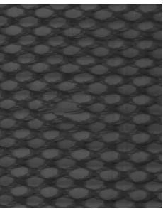
The noise is inevitably generated in the processes of image acquisition and transmission, which affects image input, collection, processing and even output. Therefore, it is necessary to suppress noise. In order to suppress noise and improve image quality, the smoothing preprocessing is adopted to eliminate the impact of noise. Citing mosquito nets as an example, acquired image with size of 280 by 340 pixels is shown in Figure 2.
FIGURE 2. Defect image of mosquito nets.
The methods of image smoothing can fall broadly into two categories. One is global processing, the other is local processing. Since local processing has high speed and computational efficiency which are critical in real-time processing, it was adopted in this paper. Local processing corrects the image by a local operator. Median filter and mean filter are two typical local operators.
Median filter means that the pixel grey value with coordinate (i, j) in the source image would be replaced by the value calculated on all the neighborhood pixels according to the following Eq. (1).
niseven
x x
odd is n x
mid j i f
n n n
n
], [
2 1
,
) x ... x , x , x ( ) , (
1 2 2 2
3 2 1
(1)
Where x is in the neighborhood of pixel (i, j) and arranged in order of grey value,n is the size of the neighborhood.
Mean filter means that the pixel grey value with coordinate (i, j) in source image would be replaced by the mean value calculated on all the neighborhood pixels by Eq. (2).
n
i i x n j i f
1
1 ) , (
(2)
In order to select the appropriate smoothing method, a comparative analysis is made between mean filter and median filter. On one hand, the main noise is Gaussian noise in the image acquisition, while median filter is not effective to Gaussian noise. On the other hand, as shown in Table Ⅰ, it is concluded that the larger template, the more time required; and mean filter consumes more little time than median filter. Considering these aspects, mean filter is obviously superior to median filter in this system.
TABLE I. Time consumption comparison between the mean filter and median filter (time unit: ms).
Image Acquisition
Image Preprocessing
Image Segmentation
Morphological Operation
Feature Extraction and Defects Identification
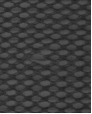
Therefore, a 3×3 mean template is selected to eliminate the noise. The effect processed by mean filter is shown in Figure 3.
FIGURE 3. Effect processed by mean filter.
ADAPTIVE THRESHOLD SEGMENTATION
BASEDONBRIGHTNESS
As shown in Figure 2, the texture of mesh fabric is obvious, and the gray values of foreground and background are different, so the image segmentation should be adopted.
Image segmentation is a method by which the image is divided into several areas with specific properties, in which the interested targets can be acquired. The segmentation quality will affect the defect extraction directly. The common image segmentation methods are based on the threshold, the region, and the edge. Currently, segmentation quality which has no uniform standards is assessed depending on the application and the effect. As the online inspection system has a higher requirement of real-time, the segmentation method based on threshold is selected. In addition, due to the fact that there is inconsistency in the brightness of the image, the adaptive threshold segmentation method based on the brightness is proposed.
The steps of adaptive threshold segmentation based on the brightness are as follows: (1) According to the brightness, the image is divided into several regions to be segmented; (2) the appropriate threshold Tk for each region is selected; (3) the image is segmented according to the selected threshold Tkand Eq. (3).
k k T j i f
T j i f j
i g
) , ( 0
) , ( 255 ) ,
( (3)
Where i, j are respectively the row and column numbers of pixel, f (i, j) is the gray value of (i, j), and
g (i, j) is the gray value of (i, j) after segmentation.
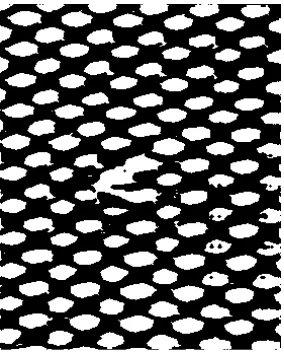
As the linear CCD camera is used for image capture, the images have the same brightness from top to down, but the brightness changes from left to right. Hence, each image is divided into three regions from left to right based on the brightness. Since the gray values in each region are basically the same, the average value of each region is selected as the threshold Tk, and then the image is segmented according to Eq. (3). As shown in Figure 4, the segmentation effect is remarkable.
FIGURE 4. Effect of adaptive threshold segmentation based on the brightness.
FEATUREEXTRACTION
Morphological Operation
In this paper, the grid size of mesh fabric is selected as the defect feature, while due to the production process and the texture characteristics, there are some normal small holes in the image (as shown in Figure 4), which have an impact on the inspection speed. So we should eliminate the small holes. The dilation operator in morphology can eliminate this effect.
The function of the dilation operator is to bridge the adjacent target, which has good performance in eliminating the holes. With the image X and structural element S, XS is defined that X isdilated by S, as shown in Eq. (4):
} ]
[ |
{
S x S x x
X (4)
Where x is the element of the image X, is a null set. The structural element S is:
0 1 0
1 1 1
0 1 0
After dilated by the structure element S, the small holes in Figure 4 are eliminated basically, as shown in Figure 5.
FIGURE 5. Effect processed by dilation operator.
Mesh Fabric Defects Identification Based On Texture Features
According to the selected features and texture characteristics, a defect recognition algorithm can be designed. The process steps are as follows:
(1) Start scanning from the first line of the image, and find the first white point (gray value 255) as the seed point.
(2) Make the region growing by the seed point. If there is white point around the seed point, push it into the stack and set the seed point black (gray value 0).
(3) Pop the top point in the stack in turn, then judge whether there is white point around the point. If there is, push it into the stack; otherwise set it black. The step will be over until stack is null.
(4) Record the number of white points (that indicates the hole size), minimum and maximum of row and column numbers in the process of region growing.
(5) After having finished the first line, repeat the above steps until all hole sizes are marked up according to the maximum row number.
(6) Mark the defect regions according to the set threshold and assess the quality of products according to these holes’ sizes.
A proposed defect recognition algorithm has been designed, debugged, and optimized according to the above process. The implementation result of the algorithm is shown in Figure 6, where the x-axis indicates the column number of the meshes, and the y-axis indicates the area of the meshes in the corresponding rows.
FIGURE 6. Implementation result of proposed algorithm.
IMPLEMENTATIONANDRESULTS
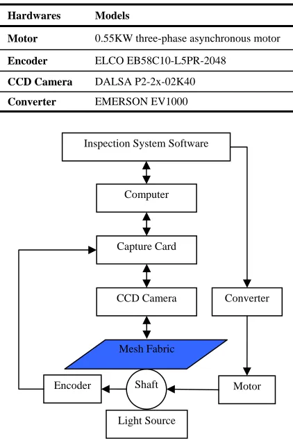
The online defect inspection system of mesh fabric was established by integrating the motor, encoder, linear CCD camera, capture card, industrial computer, converter, light source, and inspection system software. The main hardware models are shown in
Table Ⅱ, and the working principle is shown in
TABLE II. Main hardware models.
Hardwares Models
Motor 0.55KW three-phase asynchronous motor
Encoder ELCO EB58C10-L5PR-2048
CCD Camera DALSA P2-2x-02K40
Converter EMERSON EV1000
FIGURE 7. Working principle of inspection system.
At first, the processing procedure including the morphological operation was implemented and its time consumption is shown in Table Ⅲ marked by previous procedure. The dilation operator in morphological operation took 156ms and the subsequent defect identification took 15ms, while defect identification alone took 16ms. In addition, dilation operator had little effect on accuracy. Hence considering the real-time and the inspection speed, morphological operation was abandoned.
The final procedure and its time consumption are shown in Table Ⅲ. Firstly, the preprocessing method (mean filter) was adopted to eliminate the noise, which took about 31ms. Secondly, according to the brightness of the image, the adaptive threshold segmentation based on the brightness was proposed to eliminate the impact of the uneven illumination and effectively separate the background and foreground. Finally, the defect identification method based on texture features, which took about 16ms, was presented to detect the defects. The whole processing procedure that just took about 48ms had high real-time performance.
TABLE III. Time consumption comparison between previous and final processing procedures (time unit: ms).
Processing Methods Previous Procedure
Final Procedure Preprocessing 31 31
Image Segmentation 1 1
Morphological
Operation 156 0 Feature Extraction and
Defect Identification 15 16
Total 203 48
Online inspection system software of mesh fabric has been developed based on above methods. Inspection results are shown in Figure 8.
FIGURE 8. Inspection results. Inspection System Software
Computer
Shaft Encoder
Capture Card
CCD Camera
Motor Converter
Mesh Fabric
CONCLUSIONS
The appearance defect online inspection system of mesh fabric based on machine vision has been developed. According to the main noise type of the images, the preprocessing method of mean filter is selected to eliminate the noise. Based on the brightness of the image, the adaptive threshold segmentation method is proposed to eliminate the impact of the uneven illumination and effectively separate the background and foreground. By analyzing the mesh fabric texture characteristics and defect features, the mesh fabric defect identification method based on texture features has been presented. The inspection results have shown when the online inspection speed reaches 60m/min, the defect recognition rate can reach 95% or more and the online inspection system can meet the automation requirements of enterprises well.
ACKNOWLEDGEMENTS
This research was funded in part through a grant by the National Natural Science Foundation of China (51075130, 51205115), Natural Science Foundation of Hubei Province (2009CDA151, 2010CDB03102), Academic Leaders of Wuhan (201051730552) and Science Research Program of Hubei Provincial Department of Education (Q20121408).
REFERENCES
[1] Golnabi, H.; Asadpour, A.; Design and application of industrial machine vision systems; Robotics and Computer-Integrated Manufacturing 2007, 23, 6, 630-637.
[2] Colet, P.; Machine vision aids quality inspection; Quality 2006, 45, 10, 22-23. [3] Li R. et al; FPGA-based multi-sensor real time
machine vision for banknote printing; In IS and T Electronic Imaging - Image Processing: Machine Vision Applications II; SPIE: USA, 2009; Vol. 7251.
[4] Dar, I.M.; Automated vision based quality control for electro-optical module
manufacturing; In Machine Vision
Applications, Architecture, and Systems Integration VI; SPIE: USA, 1997; Vol. 3205, pp. 236-245.
[5] Karathanassi, V.; Lossifidis, Chr.; Rokos, D.; Application of machine vision techniques in the quality control of pharmaceutical solutions; Computers in Industry 1996, 32, 2, 169-179.
[6] Adel, G.; Faten, F.; Radhia, A.; Assessing cotton fiber maturity and fineness by image analysis; Journal of Engineered Fibers and Fabrics 2011, 6, 2, 50-60.
[7] Sun, G.D.; Zhao, D.X.; Lin, Q.; Online defects inspection method for velcro based on image processing; In 2010 2nd International Workshop on Intelligent Systems and Applications; IEEE: USA, 2010; pp. 1118-1121.
[8] Wu, L.L. et al; Identification of weed/corn using BP network based on wavelet features and fractal dimension; Scientific Research and Essay 2009, 4, 11, 1194-1200.
[9] Medvedeva, E.V.; Kurbatova, E.E.; A two-stage image preprocessing algorithm; Pattern Recognition and Image Analysis 2011, 21, 2, 304-308.
[10] Wan, Y.; Yao, L.; Xu, B.; Automatic segmentation of fiber cross sections by dual thresholding; Journal of Engineered Fibers and Fabrics 2012, 7, 1, 114-120.
[11] Ma, J.; Theiler, J.; Perkins, S.; Two realizations of a general feature extraction framework;
Pattern Recognition 2004, 37, 5, 875-887.
AUTHORS’ ADDRESSES Guodong Sun, PhD Huan Li
Xin Dai
Daxing Zhao, PhD Wei Feng
School of Mechanical Engineering Hubei University of Technology 1 Lijiadun Road