(UDC: 62-592.11)
Thermomechanical stress analysis of vehicles gray cast brake
A. Belhocine1*, M. Bouchetara1
1
Department of Mechanical Engineering, USTO Oran University L.P 1505 El -MNAOUER, USTO 31000 Oran (Algeria)
*Corresponding author
Abstract
The main purpose of this study is to analyse the thermo-mechanical behavior of the dry contact between the brake disc and pads during the braking phase. The simulation strategy is based on computer code ANSYS11. The modeling of transient temperature in the disk is actually used to identify the factor of geometric design of the disk to install the ventilation system in vehicles. The thermal-structural analysis is then used coupling to determine the deformation established and the Von Mises stresses in the disk, the contact pressure distribution in pads. The results are satisfactory when compared to those found in the literature.
Keywords: Brake discs, heat flux, heat transfer coefficient, von mises stress, contact pressure
1. Introduction
The braking system represents one of the most fundamental safety-critical components in modern passenger cars. Therefore, the braking system of a vehicle is undeniably important, especially in slowing or stopping the rotation of a wheel by pressing brake pads against rotating wheel discs (Valvano and Lee 2000). The investigation of the localized thermal phenomena such as hot spotting and hot banding (Anderson and Knapp 1990; Lee and Dinwiddie 1998) requires a fully coupled thermo-elastic analysis and thus, it is beyond the scope of the current study. This separate work is underway to include the localized thermal effects in the proposed design process and will be reported in the future.
Braking performance of a vehicle can significantly be affected by the temperature rise in the brake components. The frictional heat generated at the interface of the disc and the pads can cause a high temperature. Particularly, the temperature may exceed the critical value for a given material, which leads to undesirable effects, such as brake fade, local scoring, thermo elastic instability, premature wear, brake fluid vaporization, bearing failure, thermal cracks, and thermally excited vibration (Abu Bakar et al. 2010).
(Ouyang et al. 2009) in their recent work found that temperature could also affect the vibration level in a disc brake assembly. In a recent work, (Ouyang et al. 2009; Hassan et al. 2009) employed finite element approach to investigate thermal effects on disc brake squeal using dynamic transient and complex eigenvalue analysis, respectively. Braking system is the single most important safety feature of every vehicle on the road. The ability of the braking system to bring a vehicle to safe controlled stop is absolutely essential in preventing accidental vehicle damage and personal injury. The braking system is composed of many parts, including friction pads on each wheel, a master cylinder, wheel cylinders, and a hydraulic control system (Sivarao et al. 2000). Disc brake consists of cast-iron disc which rotates with the wheel, caliper fixed to the steering knuckle and friction material (brake pads). When the braking process occurs, the hydraulic pressure forces the piston and therefore pads and disc brake are in sliding contact. Set up force resists the movement and the vehicle slows down or eventually stops. Friction between disc and pads always opposes motion and the heat is generated due to conversion of the kinetic energy (Kuciej and Grzes 2011). The three-dimensional simulation of thermo-mechanical interactions on the automotive brake, showing the transient thermo-elastic instability phenomenon, is presented for the first time in this academic community (Cho and Ahn 2001).
In this work, we will make a model of the thermo-mechanical behavior of the dry contact between the disc of brake pads at the time of braking phase, the strategy of calculation is based on the software Ansys 11 (Zhang. et al. 2009). This last is elaborate mainly for the resolution of the complex physical problems. The numerical simulation of the coupled transient thermal field and stress field is carried out by sequentially thermal-structurally coupled method based on Ansys.
2. Heat flux entering the disc
In a braking system, the mechanical energy is transformed into a calorific energy. This energy is characterized by a total heating of the disc and pads during the braking phase. The energy dissipated in the form of heat can generate temperature rise ranging from 300°C to 800°C. Generally, the thermal conductivity of the material of the brake pads is lower than on the disc (kp kd).We consider that the heat quantity produced will be completely absorbed by the brake disc. The heat flux evacuated of this surface is equal to the friction power. The initial heat flux
0
q entering the disc is calculated by the following formula (Reimpel 1998):
0 0
1
2 2 d p
mgv z q
A
(1)
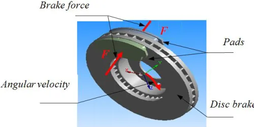
Fig. 1 shows the ventilated disc – pads and the applied forces.
The loading corresponds to the heat flux on the disc surface. The dimensions and the parameters used in the thermal calculation are recapitulated in Table 1.
Item Values
Inner disc diameter, mm 66
Outer disc diameter, mm 262
Disc thickness (TH) ,mm 29
Disc height (H) ,mm 51
Vehicle mass m, kg 1385
Initial speed v0, v0km/h 28
Deceleration a, m/s2tstop 8
Effective rotor radius Rrotor ,mm 100.5
Rate distribution of the braking forces , % 20
Factor of charge distribution on the disc
p 0.5
Surface disc swept by the pad Ad,mm2 35993
Table 1. Geometrical dimensions and application parameters of automotive braking.
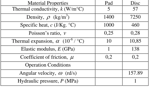
The disc material is gray cast iron (GFC) with high carbon content (Gotowicki, et al. 2005), with good thermo-physical characteristics and the brake pad has an isotropic elastic behavior whose thermo- mechanical characteristics adopted in this simulation in the transient analysis of the two parts are recapitulated in Table 2.
Material Properties Pad Disc
Thermal conductivity, k (W/m°C) 5 57
Density, (kg/m3) 1400 7250
Specific heat, c (J/Kg. °C) 1000 460
Poisson‟s ratio, v 0,25 0,28
Thermal expansion, (10-6 / °C) 10 10,85
Elastic modulus, E (GPa) 1 138
Coefficient of friction, 0,2 0,2
Operation Conditions
Angular velocity, (rd/s) 157.89
Hydraulic pressure, P (MPa) 1
Table 2. Thermo-elastic properties used in simulation.
3. Modeling in Ansys CFX
The air flow characteristics around the brake components are highly complex and they can vary significantly with the underbody structure as well as the component shapes. Instead of using empirical equations, which are commonly used in the thermal analysis (Dittrich and Lang 1984; (Fukano and Matsui 1986), the average heat transfer coefficients are calculated from the measured cooling coefficients by an iteration algorithm. Since the cooling coefficients account for all three modes of heat transfer, the estimated heat transfer coefficients include the equivalent radiation heat transfer coefficient.
order to facilitate the mesh on which that one will export the results towards CFX using the command "Output to cfx" (Ansys 1996). After obtaining the model on CFX Pre and specifying the boundary conditions, we must define these physical values comинг into play on CFX to start calculating.
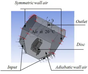
The disc is related to four adiabatic surfaces and two surfaces of symmetry in the fluid domain whose ambient temperature of the air is taken equal at 20 °C (Carlos and Galindo 2001). In order not to weigh down calculation, an irregular mesh is used in which the meshes are broader where the gradients are weaker (non-uniform mesh).
Fig. 2 shows the elaborate CFD model which will be used in ANSYS CFX Pre.
Fig. 2. Brake disc CFD model.
In this step, one declares all of the physical characteristics of the fluid and the solid. We introduce into the library the physical properties of used materials. In this study we selected a gray cast iron material (FG 15) with its thermal conductivity (57 W/m °C). Since the aim of this study is to determine the temperature field in a disc brake during the braking phase of a vehicle of average class, we take the following temporal conditions:
Braking time= 3.5 [s]
Increment time = 0.01 [s]
Initial time = 0 [s]
Before starting the calculation and the analysis with ANSYS CFX PRE, it is ensured that the model does not contain any error.
Fig. 3. Distribution of heat transfer coefficient on a ventilated disc in the stationary case (FG 15).
4. Meshing of the disc
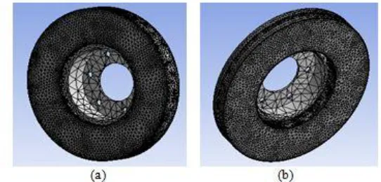
The elements used for the meshing of the full and ventilated disc are tetrahedral three-dimensional elements with 10 nodes (isoparametric) (Fig.4). In this simulation, the meshing was refined in the contact zone (disc-pad).This is important because in this zone the temperature varies significantly. Indeed, in this strongly deformed zone, the thermomechanical gradients are very high. This is why the correction taking into account of the contact conditions involves the use of a refined mesh.
Fig. 4. Meshing of the disc (a) full disc (172103 nodes -114421 elements)
(b) ventilated disc (154679 nodes - 94117 elements).
5. Loading and boundary conditions
The thermal loading is characterized by the heat flux entering the disc through the real contact area (two sides of the disc). The initial and boundary conditions are introduced into module ANSYS Workbench. The thermal calculation will be carried out by choosing the transient state and by introducing physical properties of the materials. The selected data for the numerical application are summarized as follows:
Total time of simulation = 45 [s]
Increment of initial time = 0.25 [s]
Increment of maximal initial time = 0.5 [s]
Initial Temperature of the disc = 60 [°C]
Material: Gray Cast iron (FG 15).
6. Results and discussions
The modeling of temperature in the disc brake will be carried out by taking account of the variation of a certain number of parameters such as the type of braking, the cooling mode of the disc and the choice of disc material. The brake discs are made of cast iron with high carbon content; the contact surface of the disc receives an entering heat flux calculated from the equation (1).
6.1 Influence of construction of the disc
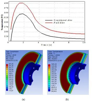
Fig. 5. Temperature distribution of a full (a) and ventilated disc (b) of cast iron (FG 15).
surface disc-pads. The strong rise in temperature is due to the short duration of the braking phase and to the speed of the physical phenomenon. Of the two types of discs, one notices that starting from the first step of time one has a fast rise in the temperature of the disc followed by a fall of the temperature after a certain time of braking.
We quickly notice that for a ventilated disc out of cast iron FG15 the temperature increases until Tmax = 345°C at the moment t = 1.85s, then it decreases rapidly in the course of time. The
variation in temperature between a full and ventilated disc having same material is about 60°C at the moment t = 1.88s. We can conclude that the geometric design of the disc is an essential factor in the improvement of the cooling process of the discs.
7. Coupled thermo-mechanical analysis
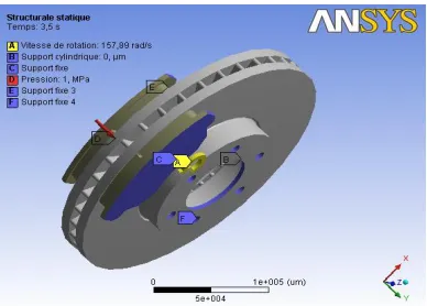
The purpose of the analysis is to predict the temperatures and corresponding thermal stresses in the brake disc when the vehicle is subjected to sudden high speed stops as can occur under autobahn driving conditions (Koetniyom et al. 2002). A commercial front disc brake system consists of a rotor that rotates about the axis of a wheel, a caliper-piston assembly where the piston slides inside the caliper, which is mounted to the vehicle suspension system, and a pair of brake pads. When hydraulic pressure is applied, the piston is pushed forward to press the inner pad against the disc and simultaneously the outer pad is pressed by the caliper against the disc (Nouby and Srinivasan 2009). In a real car disc brake system, the brake pad surface is not smooth at all. (Abu Bakar and Ouyang 2008) adjusted the surface profiles using measured data of the surface height and produced a more realistic model for brake pads. Fig. 6 shows the finite element model and boundary conditions embedded configurations of the model composed of a disc and two pads. The initial temperature of the disc and pads is 20°C, and the surface convection condition is applied to all surfaces of the disc and the convection coefficient (h) of
2
5 / o
W m C is applied at the surface of the two pads. The FE mesh is generated using three-dimensional tetrahedral element with 10 nodes (solid 187) for the disc and pads. There are about 185901 nodes and 113367 elements are used (Fig. 7).
In this work, a transient thermal analysis will be carried out to investigate the temperature variation across the disc using Ansys software. Further structural analysis will also be carried out by coupling thermal analysis.
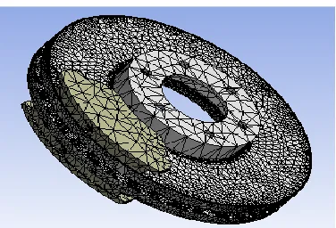
Fig. 7. Refined mesh of the model.
7.1 Thermal deformation
Fig. 8 gives the distribution of the total distortion in the whole (disc-pads) for various moments of simulation. For this figure, the scale of values of the deformation varies from 0 µm with 284
µm. The value of the maximum displacement recorded during this simulation is at the moment t=3,5 s which corresponds to the time of braking. One observes a strong distribution which increases with time on the friction tracks and the external crown and the cooling fins of the disc. Indeed, during a braking, the maximum temperature depends almost entirely on the heat storage capacity of disc (on particular tracks of friction) this deformation will generate a dissymmetry of the disc following the rise of temperature which will cause a deformation in the shape of an umbrella.
Fig. 8. Total distortion distribution.
7.2 Von Mises stress distribution
Fig. 9. Von Mises stress distribution.
7.3 Contact pressure
Due to thermal deformation, contact area and pressure distribution also change. Thermal and mechanical deformations affect each other strongly and simultaneously. As pressure distribution is another important aspect concerned with this research, it will be studied in the context of uneven temperature distributions. Contact analysis of the interfacial pressure in a disc brake without considering thermal effects was carried out in the past, for example, in (Tirovic and Day 1991). Brake squeal analysis in recent years always includes a static contact analysis as the first part of the complex eigenvalue analysis (Tirovic and Day 1991; Valvano and Lee 2000; Ouyang et al. 2003; Lee et al. 2003).
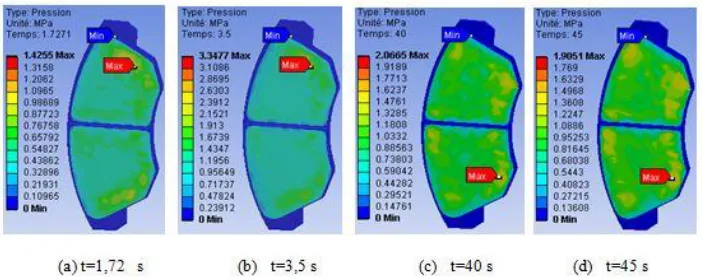
Fig. 10 shows the contact pressure distribution in the friction interface of the inner pad taken for at various times of simulation.For this distribution the scale varies from 0 MPa to 3,3477 MPa and reached a value of pressure at the moment t=3,5 s which corresponds to the null rotational speed. It is also noticed that the maximum contact pressure is located on the edges of the pad of the entry and goes down towards the exit from the area from friction. This pressure distribution is almost symmetrical compared to the groove and it has the same tendency as that of the distribution of the temperature because the highest area of the pressure is located in the same sectors. Indeed, at the time of the thermo-mechanical coupling 3d, the pressure carries out to lead to the not-axisymmetric field of the temperature. This last affects thermal dilation and leads to a variation of the contact pressure distribution.
8. Conclusion
In this publication, we presented the analysis of the thermo-mechanical behavior of the dry contact between the brake disc and pads during the braking process; the modeling is based on the ANSYS 11.0. We have shown that the ventilation system plays an important role in cooling disks and provides a good high temperature resistance. The results of the analysis showed that temperature field and stress field in the process of braking phase were fully coupled. The temperature, Von Mises stress and the total deformations of the disc and contact pressures of the pads increase as the thermal stresses are added to mechanical stress which causes the crack propagation and fracture of the bowl and wear of the disc and pads. Regarding the calculation results, we can say that they are satisfactory in comparison with those commonly found in the literature investigations. It would be interesting to solve the problem of thermo-mechanical disc brakes with an experimental study to validate the numerical results, for example on test benches, in order to show a good match between the model and reality.
Извод
Термомеханичка анализа притиска код возила са кочницама од сивог
лима
Ali Belhocine1*, Mostefa Bouchetara1
1
Department of Mechanical Engineering, USTO Oran University L.P 1505 El -MNAOUER, USTO 31000 Oran (Algeria)
*Corresponding author
Резиме
Основни циљ овог рада је да се анализирају термо-механичке особине сувог контакта између кочионог диска и кочионе плочице у фази кочења. Стратегија симулација заснива се на компјутерском коду ANSYS11. Моделирање тренутне температуре у диску заправо се користи за идентификацију фактора геометријског дизајна диска како би се уградио вентилациони систем у возилима. Термо-структурна анализа се, затим, користи за утврђивање настале деформације, Фон Мизеовог притиска у диску и дистрибуцију притиска у контакту са кочионим плочицама. Резултати су задовољавајући у односу на оне који се могу наћи у литератури.
Кључне речи: Кочиони дискови, топлотни флукс, коефицијент преноса топлоте, Фон Мизеов притисак, контактни притисак
References
Abu Bakar A. R. and Ouyang H., (2008). Wear prediction of friction material and brake squeal using the finite element method, Wear, 264(11-12), 1069-1076.
Abu Bakar. A. R, H. Ouyang, L. C. Khai and M.S. Abdullah, (2010). Thermal Analysis of a Disc Brake Model Considering a Real Brake Pad Surface and Wear, Int. J. Vehicle Structures & Systems, 2(1), 20-27.
ANSYS v.11, (1996). Ansys user manual. ANSYS, Inc., Houston, USA.
Carlos. H and Galindo. L, (2001). Evaluating new ways of conducting convective heat dissipation experiments with ventilated brake discs "Cranfield University, Bedfordshire, MK43 OAL.
Cho.C and Ahn S., (2001). Thermo-elastic analysis for chattering phenomenon of automotive disk brake KSME International Journal, Volume 15, Issue 5, pp. 569-579.
Dittrich. H and Lang, R., (1984). Finite-Element Analysis of the Thermal Loads Acting on a Passenger Car Brake Disk, Automobiltechnische Zeitschrift, Vol. 86, No. 6, pp. 265-269. Fukano. A and Matsui. H., (1986). Development of Disc-Brake Design Method Using Computer
Simulation of Heat Phenomena, SAE 860634.
Gao C.H. and Lin X.Z., (2002). Transient temperature field analysis of a brake in a non- axisymmetric threedimensional model, J. Materials Processing Technology, 129, 513-517. Hassan M.Z., Brooks P.C., and Barton. D.C., (2009). A predictive tool to evaluate disk brake
squeal using a fully coupled thermo-mechanical finite element model, Int. J.Vehicle Design, 51(1/2), 124-142.
Koetniyom S., Brooks P. C. and Barton D. C., (2002). The development of a material model for cast iron that can be used for brake system analysis Proceedingsof the Institution of Mechanical Engineers, Part D:Journal of Automobile Engineering 216: 349.
Kuciej.M, Grzes.P., (2011). The comparable analysis of temperature distributions assessment in disc brake obtained using analytical method and fe model, journal of kones powertrain and transport, vol. 18, no. 2.
Lee .K and Dinwiddie .R. B., (1998). Conditions of Frictional Contact in Disk Brakes and Their Effects on Brake Judder,” SAE 980598.
Lee, S. and Yeo, T., (2000). Temperature and coning analysis of brake rotor using an axisymmetric finite element technique, Proc. 4th Korea-Russia Int. Symp. On Science & Technology, 3, 17-22.
Lee, Y. S., Brooks, P. C., Barton, D. C., and Crolla, D. A., (2003). A predictive tool to evaluate disc brake squeal propensity Part 1: The model philosophy and the contact problem. International Journal of Vehicle Design 31: 289-308.
Nouby M. and Srinivasan K., (2009). Parametric Studies of Disc Brake Squeal using Finite Element Approach” Anna University Chennai-600025 India.Jurnal Mekanikal. December, No. 29, 52-66.
Numerical and experimental analysis of a pegs-wing ventilated disk brake rotor, with pads and cylinders, 10th EAE Eur.Automot. Cong – Paper EAEC05YUAS04– P 5, June 2005. Ouyang, H., AbuBakar A.R., and Li L., (2009). A combined analysis of heat conduction, contact
pressure and transient vibration of a disc brake, Int. J. Vehicle Design, 51(1/2), 190-206. Ouyang, H., Cao, Q., Mottershead, J. E., and Treyde, T., (2003). Vibration and squeal of a disc
brake: modelling and experimental results. IMechE Journal of Automotive Engineering 217: 867-875.
Reimpel J., (1998). Braking technology. Vogel Verlag, Würzburg.
Sivarao, Amarnath M., Rizal M.S., Kamely A., (2000). An Investigation Toward Development Of Economical Brake Lining Wear Alert System. International Journal of Engineering & Technology IJET Vol: 9 No: 9 pp251-256.
Tirovic M., and Day A. J., (1991). Disc brake interface pressure distribution. IMechE Journal of Automobile Engineering 205: 137-146.
Valvano T. and Lee K., (2000). An Analytical Method to Predict Thermal Distortion of a Brake Rotor, SAE 2000-01-0445.