International Journal of Advanced Technology in Engineering and Science www.ijates.com
Volume No.02, Issue No. 07, July 2014 ISSN (online): 2348 – 7550
CFD ANALYSIS ON A SIMPLE CARBURETOR FOR
DIFFERENT POSITIONS OF THROTTLE VALVE
AND FUEL NOZZLE VALVE
Rangu P
1, Ganesha T
2, M. C. Math
3 1M.Tech student, Department of Thermal Power Engineering, VTU, PG-Center, Mysore(India)
2Assistant Professor, Department of Thermal Power Engineering, VTU, PG-Center, Mysore( India)
3Associate Professor, Department of Thermal Power Engineering, VTU, PG-Center, Mysore(India)
ABSTRACT
Carburetor plays a crucialrole in SI engine performance which supplies correct mixture of fuel airat the right time. One of the important factors that affect the fuel consumption is the design of the carburetor. The throat of the carburetor provides required pressure drop in the venturi tube of the carburetor device. Currently, alternative fuels like LPG, CNG, etc. are gaining attention all over the world because of their ecofriendly nature. So the design of the carburetor is important. To get a better economy and uniform distribution of fuel air mixture, it required to design the carburetor with an effective analytical tool or software. In this work,CFD (FLUENT 14) analysis was carried out on a simple carburetor to find pressure drop and velocity profile for different throttle valve angle (300,400,500,600,700,800and 900) and fuel discharge nozzle angle(330,360 and 390). The results obtained from the analysisare analyzed for optimum design of a carburetor. Maximum pressure drop was observed at the throttle angle of 900. Pressure distribution was observed more uniform atfuel discharge nozzle angle of 330.
Keywords
- Carburetor, Throttle valve, Nozzle angle, Pressure Drop, and Velocity distributionI. INTRODUCTION
SI engines generally use volatile liquids. The preparation of the air fuel mixture is done outside the engine cylinder. The fuel droplets that remain in suspension also continue to evaporate and mix with air during suction and compression processes also. So carburetion is required to provide a combustible mixture of fuel and air in required quantity and quality[1]. The process of forming a combustible fuel air mixture by mixing the right amount of fuel with air before admission to the cylinder of the engine is called carburetion and the device is known as a carburetor. The flow through these internal passages may be quite complexand passages is short length[2].
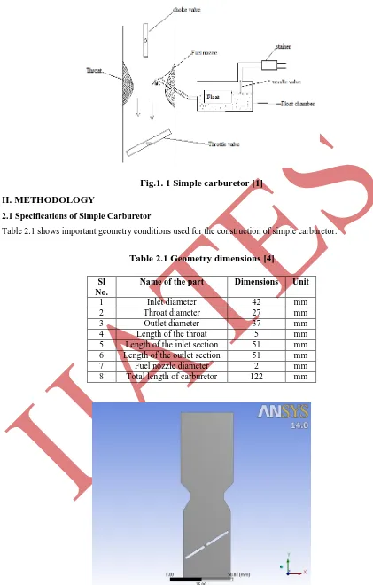
1.1 Working principal of simple carburetor
Fig.1. 1 Simple carburetor [1]
II. METHODOLOGY
2.1 Specifications of Simple Carburetor
Table 2.1 shows important geometry conditions used for the construction of simple carburetor.
Table 2.1 Geometry dimensions [4]
Sl No.
Name of the part Dimensions Unit
1 Inlet diameter 42 mm
2 Throat diameter 27 mm
3 Outlet diameter 37 mm
4 Length of the throat 5 mm
5 Length of the inlet section 51 mm
6 Length of the outlet section 51 mm
7 Fuel nozzle diameter 2 mm
International Journal of Advanced Technology in Engineering and Science www.ijates.com
Volume No.02, Issue No. 07, July 2014 ISSN (online): 2348 – 7550
2.2 Creation of 2D model and Procedure
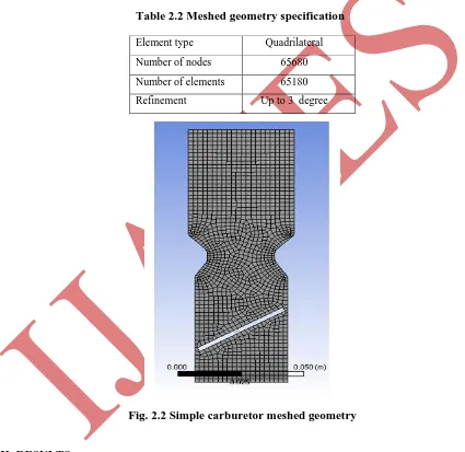
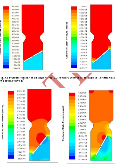
Fig. 2.1 shows a simple carburetor model generated by usingANSYS-14 workbench software.Meshing of the model was carried out inANSYS 14 software. Table 2.2 shows specifications of meshed model. Fig. 2.2 shows the meshed model of a simple carburetor. In order to carry the analysis, the meshed model is introduced to the CFD tool (ANSYS FLUENT 14). Proper boundary conditions were applied to the model. In this case, the effect of the variation of throttle valve and fuel discharge nozzle angle on the flow across the carburetor is studied. The analysis were carried out for various nozzle anglesi.e., θ =33º, 36º and 390 where θ is the angle between fuel discharge nozzle and the vertical axis of the carburetor. An attempt has also made to study the effect of different orientation of the throttle valve i.e., ϕ = 30º, 40º, 50º, 60º, 70º, 80º, and 90º.
Table 2.2 Meshed geometry specification
Element type Quadrilateral
Number of nodes 65680
Number of elements 65180
Refinement Up to 3 degree
Fig. 2.2 Simple carburetor meshed geometry
III. RESULTS
3.1 Effect of throttle valve position on air pressure at the throat section
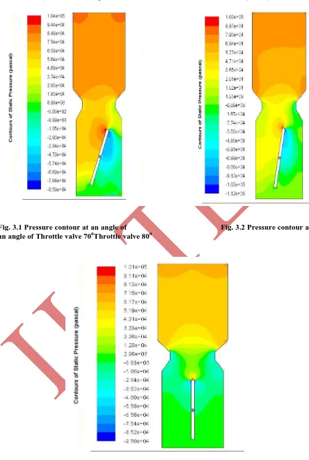
Fig. 3.1 Pressure contour at an angle of Fig. 3.2 Pressure contour at an angle of Throttle valve
30
0Throttle valve 40
0International Journal of Advanced Technology in Engineering and Science www.ijates.com
Volume No.02, Issue No. 07, July 2014 ISSN (online): 2348 – 7550
Fig. 3.1 Pressure contour at an angle of Fig. 3.2 Pressure contour at
an angle of Throttle valve 70
0Throttle valve 80
0Fig. 3.1 to 3.7 indicatesthe pressure at the throat of the venturi when the throttle valve is30º, 40º, 50º, 60º, 70º, 80º and 90º respectively. It is seen from Fig. 3.1 to 3.7 shows that the pressure at the throat section has decreased gradually with the increase in the throttle valve angle. It is minimum (32.3kPa) at 90º and maximum (101.1kPa) at 30º throttle valve position. With the increase in the throttle valve angle from 30º to 90º, the air velocity has increased, consequently the pressure at the throat section has decreased. This has a greater effect on the mixture strength. With the increase in pressure drop at the throat section, amount fuel entering into the throat section increases and makes the mixture progressively rich. This happens when load increases from zero to 100%. But, this phenomena is undesirable for practical SI engine when it is fitted with a simple carburetor. To avoid this problem, simple carburetor is needed extra attachments such as mixture enrichment circuit, idling circuits.
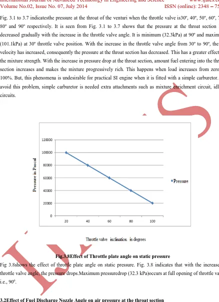
Fig.3.8Effect of Throttle plate angle on static pressure
Fig 3.8shows the effect of throttle plate angle on static pressure. Fig. 3.8 indicates that with the increase in throttle valve angle, the pressure drops.Maximum pressuredrop (32.3 kPa)occurs at full opening of throttle valve i.e., 900.
3.2Effect of Fuel Discharge Nozzle Angle on air pressure at the throat section
International Journal of Advanced Technology in Engineering and Science www.ijates.com
Volume No.02, Issue No. 07, July 2014 ISSN (online): 2348 – 7550
Fig.3.9Pressure contour at an nozzle angle of 33
0Fig.3.10Velocity contour at an nozzle
of angle
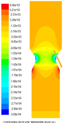
330Fig. 3.9 shows the static pressure contour and Fig. 3.10 shows the velocity contour for fuel discharge nozzle angle of 330. Fig. 3.9to 3.14 shows pressure and velocity distribution of air when it is flowing through the venturi tube for the nozzle angle of 330 , 360,and 390. Fig.3.9 shows the pressure distribution for nozzle angle of
330 . From Fig.3.9, it is clear that the pressure distribuation is uniform throughout the venturi section. Fig.3.10 shows that velocity is distributed uniformly from the inlet of the carburetor towards the throat. Fuel will be atomized and vaporised easily due to uniform distribution of pressure and velocity throught the venturi section.
Fig.3.11 Pressure contour at an nozzle angle of 36
0Fig.3.12 Velocity contour at an
nozzle
of angle 36
0the body of the carburetorand the velocity distribution is also not uniform. It may lead to improper atomization and vaporization of fuel inside the body of the simple carburetor at nozzle of 360.
Fig.3.13 Pressure contour at an nozzle angle of 39
0Fig.3.14 Velocity contour at an nozzle
of angle 39
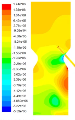
0Fig. 3.13 and 3.14 show the static pressure and velocity contour for fuel discharge nozzle angle of 390. It is clear from Fig. 3.13 and 3.14, the velocity is maximum whereas the pressure is the minimum at the throat section of the venturi of the carburetor. Pressure contour shows that the pressure is not distributed uniformly throughout the body of the carburetorand the velocity distribution is also not uniform. It may lead to improper atomization and vaporization of fuel inside the body of the simple carburetor at nozzle of 390.
IV. CONCLUSION
Following conclusions are obtained by CFD analysison simple carburetor for different throttle plate valve angle and fuel nozzle angle.
1. For various throttle plate valve angles such as 300,400,500,600,700,800 and 900, it was found that the pressure at the throat of the venturi has decreased with the increase in the throttle plate angle. It is due to the fact that with the increase in throttle angle, the air velocity increases with the drop in air pressure at the throat section. The amount of air flowing through the throat section remains same but, more amount of fuel will be sucked into the throat section due to increase in pressure drop.
2. With the increase in nozzle angles from 330to 360, and from 360 to 390, it was observed that the pressure and velocity distribution became more non-uniform. At fuel discharge nozzle angle of 330, it is observed that the pressure and velocity distribution is uniform which leads to a better atomization and vaporization of the fuel inside the body of the carburetor. So, it can be concluded that optimum fuel discharge nozzle angle must be kept at 330.
International Journal of Advanced Technology in Engineering and Science www.ijates.com
Volume No.02, Issue No. 07, July 2014 ISSN (online): 2348 – 7550
[1] Ganeshan V, Internal Combustion Engines, Edition 2 New Delhi TMH 2009.
[2] Diego A. Arias, Timothy, A. Shedd, Numerical and experimental study of air and fuel flow in small engine carburetors, 2005, University of Wisconsin Madison.
[3] Shivkumar, biradar Ebinezar, Raj Reddy,Validation of producer gas carburetor using CFD. International Journal of Latest Research in Science and Technology, 2 (6), 2013, PP 90-94.