Design, Analysis & Material Optimization of
Submersible Pump Impeller by FEA &
Experimentation
Mr. Mahesh C. Dhere Dr. A. M. Badadhe
PG Scholar Professor
Department of Mechanical Engineering Department of Mechanical Engineering RSSOER, Pune, Maharashtra, India RSCOE, Pune, Maharashtra, India
Prof. A. S. Patil Prof. M. B. Bankar
Assistant Professor Assistant Professor
Department of Mechanical Engineering Department of Mechanical Engineering RSSOER, Pune, Maharashtra, India SCSCOE, Pune, Maharashtra, India
Prof. A. K. Tarange
Assistant Professor
Department of Mechanical Engineering SCSP, Pune, Maharashtra, India
Abstract
Static analysis and Experimentation of submersible pump impeller using composite materials are used in naval applications now a day. Considering structural strength of impeller of submersible pump, weight to the strength ratio is important for this work. So, weight reduction of submersible pump is most important for optimization. Impeller weight and structure are responsible for mechanical loss that reduces the power transferred from the motor shaft to the pump impeller. The composite material made it possible to reduce the weight of mechanical component without any reduction of its capacity. The present work aims at observing the choice of E-Glass as an alternative to metal for better material optimization. In this paper a Kirloskar KS6D submersible pump impeller has been taken for design & optimization by using experimental and FEA in ANSYS 16 software. FEA approach is validated by experimental method.
Keywords: Pump Impeller, Glass Fiber, FE Analysis, Material Optimization
________________________________________________________________________________________________________
I. INTRODUCTION
Submersible pumps are very common equipment used in residence, agriculture and industrial applications. It is essential for a pump to be manufactured at low cost and consuming less power with high efficiency. A submersible pump is a kinetic device. Liquid entering the pump receives kinetic energy from the rotating impeller. Due to the centrifugal force phenomenon the impeller accelerates the fluid to a high velocity, transferring rotational energy to the liquid. That kinetic energy is available to the fluid to complete the work. The impeller is a component of a pump, usually made of material likes steel, cast iron, bronze, brass, aluminium or plastic, which transfers energy from the motor that drives the pump to the fluid being pumped by accelerating the fluid outwards from the center of rotation of the impeller. The velocity of the fluid is achieved by the impeller transfers into pressure when the outward movement of the fluid is confined by the pump casing. Impellers are usually short cylinders with an open inlet to accept incoming liquid, vanes to push the liquid radially outward, and a splined, keyed or threaded bore to accept a drive-shaft. The modeling of the impeller is done by using CATIA V5. The meshing and boundary condition application will be carried using Hypermesh. ANSYS is used for determining the variation of stresses, strains and deformation across profile of the impeller of pump.
II.PROBLEM DEFINITION
Heavy rotating weight of impeller plays a huge part in reducing mechanical efficiency of pump. Due to following conditions deformations and high stress concentration occurs in impeller
Non optimized Wall thickness and weight
Impeller axial forces acting on side walls and internal blades High torque on impeller hub
III. OBJECTIVES
The main objective of this work is to weight optimize the impeller. This can be done by replacing conventionally used MS material with the glass fiber composite material. For this following objectives needs to be achieved:
To study the existing model.
Calculate forces and boundary conditions. Carryout meshing and analysis
To carryout material optimization Testing on the fabricated model.
IV. LITERATURE REVIEW
Mr. M. Sampathkumar et. Al. [1], has carried out his work on Static and model analysis of centrifugal blowers using composite materials. He observed the choice of E-Glass as an alternative to metal for better vibration control. E-Glass, known for their superior damping characteristics are more promising in vibration reduction compared to metals. The modeling of the blower was done by solid works 2014 and proposed to design blower with Epoxy glass, analyze its strength and deformation using FEM technique. In order to evaluate the effectiveness of E-Glass and metal blower using FEA packaged (ANSYS). Mohit Patil et.al. [2], in this paper a low cost, light weight and high performance novel filament wound axial impeller of a multistage counter rotating axial compressor for compressing refrigerant as water vapor (R718) is investigated structurally. Three different fiber types were chosen as suitable materials for this study (Kevlar-49, S-Glass & Carbon fiber) with a standard epoxy resin for the composite matrix. Through means of FEA (Finite Element Analysis) method; stress, displacement and vibration analysis procedure is developed to assess the maximum stress, change in dimensions and natural frequencies of these impellers under constant operating conditions. There is scope to reduce the unsprung weight. K.Uday Kumar et.al. [3], worked in Design and Simulation of Centrifugal Pump Using Composite Materials. He proposed to design a centrifugal pump using Computer Aided Design (CAD) software with various metal alloys and Non- Metallic composite materials, analyze its strength and deformation using simulation software. In order to evaluate the effectiveness of Metal Alloys and Non- Metallic composites. Also, Analysis to find the best material to decrease the weight and increase its efficiency by using the software SOLID WORKS. Sai Raghu Vemuri et.al. [4], worked in Design and Simulation of Centrifugal Pump Composite Materials. The Contemporary blades in Centrifugal Blower used in naval applications are made up of Aluminium or Steel. He proposed to design a blower using Computer Aided Design (CAD) software with various metal alloys and Non-Metallic composite materials, analyze its strength and deformation using simulation software and evaluate the effectiveness of Metal Alloys and Non-Metallic composites. Qubo Li et.al. [8], studied Aerodynamic forces are also imparted on an impeller blade, which varies with time and position. These two forces play different roles during compressor events. Damage accumulated from these events results in the fatigue failure of impeller material and structure. Therefore, it is important to design an impeller against dynamic and fatigue failure. The finite element method has been used in the study of impeller fracture mechanics and is regarded as an important tool in the design and analysis of material and structures. Santosh Shukla et.al. [6], worked on 3D model of mixed flow pump impeller blade was developed using CATIA and with four different materials (Copper alloy, Bronze, Stainless steel and Titanium alloy) analysis was done in ANSYS 11.0 with similar loading and support conditions.
V.NUMERICAL ANALYSIS OF IMPELLER
The FEM method is used to analyze the stress state of an elastic body with a given geometry, such as Impeller. In this paper the analysis of Kirloskar KS6D submersible pump impeller is intended for study using FEM software using ANSYS.
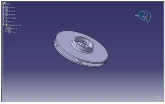
Cad Model
In this present work used the model of impellers which is made from the following dimensions. Fig 1 shows CAD model of impeller in CATIA V5.
We are using
No. of Stages 2 nos. Total Head H = 21m Head per stage 10.5 ~ 11 mtr.
Q Discharge = 120 LPM or 0.000017 x 120 m3/sec = 0.00204 m3/sec 3 HP motor 2800 rpm Dimensions of a pump impeller are:
Douter = 97mm Dshaft = 8mm Dhub = 10mm Deye = 32 mm Width = 7.25 ~ 8mm
No. of blade = 5 no.s Radius of the blade = 141.6 Width of blade = 8 mm β1= 85
Torque = 7.5 Nm
Fig. 1: CAD Model of Impeller
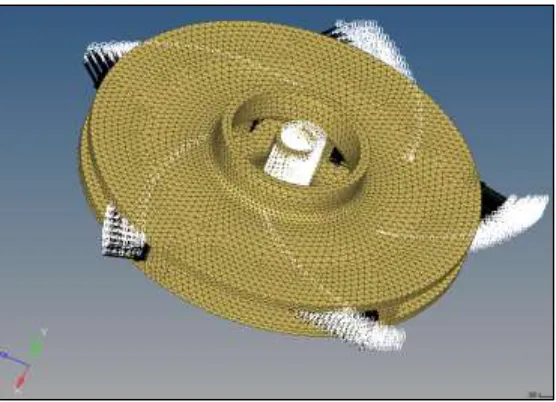
Meshing
To do the meshing of impeller Hypermesh 16 software was used. Tetra-hedral meshing type of meshing is used. Fig. 2 shows meshed model of impeller.
Number of nodes: 14041 Number of elements: 45439 Element size = 4 mm
Fig. 2: Tetra-Hedral Meshing of Pump Impeller
Boundary Condition Application on Submersible Pump Impeller
Boundary Condition Calculation: P = g h
Where,
P = Pressure of water, N/m2
= mass of density of fluid = 103 Kg/m3 H = height of fluid = 21 m
g = 9.81 m/s2
P = 206010 N/m2 = 0.21 Mpa
Fig. 3: Loading and boundary condition
Results
The results are obtained using two different material like steel which is existing material and glas fibre which is composite material used for material optimization.
Existing Material (Mild Steel)
Following table 1 shows properties of mild steel
Table - 1 Properties of Mild Steel Youngs modulas 2× 10⁵𝑀𝑝𝑎
Poissons ratio 0.3
Density 7.85× 10⁻⁶𝑘𝑔/𝑚𝑚3
Thermal expansion 1.2× 10⁻⁵/0 𝐶
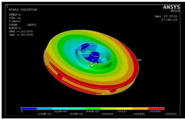
Tensile yield strength 250Mpa Compressive yield strength 250Mpa Tensile ultimate strength 460Mpa The plots obtained are as follows:
Fig. 4: Deformation Plot for Steel Impeller
Fig. 5: Stress Distribution when Load on All Blade
The von mises stress obtained are 14.30 Mpa which means the design is safe. As the design is safe, means the stresses are well within the yield stress 250 MPa, and deformation is much less there is a scope for optimization. Finite Element Analysis considering load on Single Blade of 0.21 N/mm2
Fig. 6: Applied Loads and Boundary Conditions
Fig. 7: Deformation Plot for Single Blade of Impeller
Fig. 8: Stress distribution for Single Blade
Stress value for single blade of pump impeller is 3.12 N/mm2.
Composite Material Glass Fiber
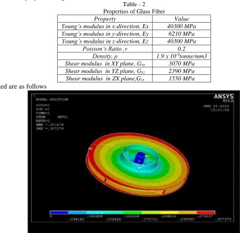
Following table 2 shows properties of glass fiber
Table - 2 Properties of Glass Fiber
Property Value
Young’s modulus in x-direction, Ex 40300 MPa Young’s modulus in y-direction, Ey 6210 MPa Young’s modulus in z-direction, Ez 40300 MPa
Poisson’s Ratio ,ν 0.2
Density, ρ 1.9 x 10⁻⁹tonne/mm3 Shear modulus in XY plane, Gxy 3070 MPa Shear modulus in YZ plane, Gyz 2390 MPa Shear modulus in ZX plane,Gzx 1550 MPa The plots obtained are as follows
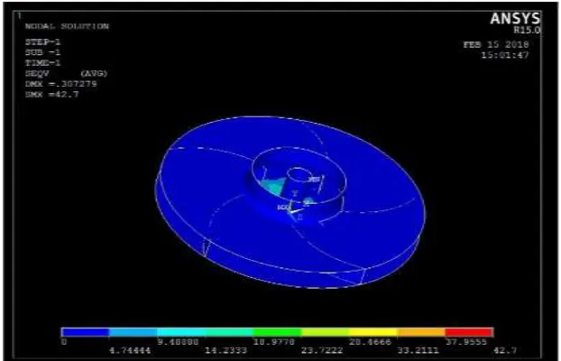
Fig. 9: Deformation Plot for Glass Fiber Impeller when Load on all Blade Deformation Produced is 0.307 mm Which Very Less
Fig. 10: Stress Plot for Glass Fiber when Load on All Blade
Fig 10 shows stress distribution plot for composite glass fiber impeller. Finite Element Analysis considering load on Single Blade of 0.21 N/mm2
Fig. 11: Deformation when Load on Single Blade
From Fig. 11. Deformation for pump impeller is 0.099 mm. and from Fig.12 Stress value for pump impeller is 15.523 N/mm2
VI. FABRICATION & TESTING
Fabrication
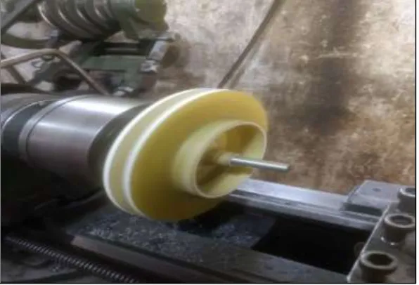
The fabrication of test model was done at K. K. engineering works, Narhe, Pune. To do glass fiber pump impeller glass fiber sheets are cut in proper shapes then fixed to the respective parts with the help of epoxy resin as an adhesive with the added cobalt 10% cobalt and hardener 10% to increase the rate of drying process as shown in figure below. Once after the reinforcement process is completed the assembly is allowed to dry for nearly 48 hours. Resin removed with vacuum sucking process after drying. And after that turning of impeller in required dimensions is takes place on lathe machine.
Fig. 13: Turning of Impeller on Lathe Machine
Experimental Set Up
Fig. 14 shows actual experimental set up for taking deformation test of composite glass fiber material with proper fixture. The pressure applied for test is same which is applied when carried out FEA that is 206010N/m2. To apply the force it is essential to convert pressure into force using area that is force equal to pressure × area (0.00073 m2).The force is 150.38 N.
Test Result
Fig. 15: Graph of Load Vs Deformation
From the graph the deformation at the force 150.38N is 0.105mm.
VII. RESULT & DISCUSSION
Comparison of FEA results for pressure of 0.21 N/mm2 on single blade of steel and glass fiber impeller. Table 3 shows the stresses developed when pressure applied on single blade of pump impeller of steel and glass fiber. The deformation of glass fiber blade is 0.099 which is validating with the actual experimental value.
Table - 3
FEA Results For Steel And Glass Fiber S. No. Material Max. Stress Max. Deformation
Steel 3.12 MPa 0.001905 mm Glass Fiber 15.523 MPa 0.099 mm
Comparison of Experimental and FEA results for pressure of 0.21N/mm2 on single blade for Glass Fiber specimen
Table - 4
Experimental and FEA Result for Glass Fiber Sr. No. Type of Analysis Max. Deformation % Error
FEA 0.099 mm
6.06 % Experimental 0.105mm
Weight Reduction:
Table - 5
Weight Comparison for Steel and Glass Fiber Sr. No. Material Weight(Kg)
Steel 0.775 Kg Glass Fiber 0.186 Kg Percentage Reduction in weight is 76%.
VIII.CONCLUSION
Weight reduction 76% is obtained without compromising the strength of the pump impeller. Critical yield strength of the material is 250MPa, from the result table it concluded that pump impeller with different iterations are below critical limit and hence they are safe in design. The iterations are carried out through the material optimization process and the glass fiber pump impeller is chosen for fabrication and testing purpose. The FEA results are compared with the experimental results with a percentage error of approximately 6.06 %. This shows a closure convergence towards the results is achieved.
REFERENCES
[2] Mohit Patil, Norbert Müller, “Structural analysis ofcontinuous fiber wound composite impellersof a multistage high-speed counter rotating axial compressor for compressing water vapor (R-718) as refrigerant using Finite Element Analysis", Elsevier Ltd.,(2013)683-693.
[3] K.Uday Kumar, N.Venkatramana Reddy, M.Ramanarasimha Reddy, “Design and Simulation of Centrifugal Pump Using Composite Materials”, International journal and magazine of engineering technology, management and research, Volume 3 (2016).
[4] Sai Raghu Vemuri, P.V Viswanath, “Design and Simulation of Centrifugal Pump Composite Materials”.
[5] Sunilkumar Raghu T,"Modeling and Analysis, Life Evaluation of Impeller of Submersible Pump to Improve Efficiency", IJSRD - International Journal for Scientific Research & Development| Vol. 4, Issue 04, 2016 |.
[6] Santosh shukla, Apurba Kumar Roy and Kaushik Kumar, “Material selection for blade of mixed flow pump impeller using ANSYS", 4th international conference on material processing and characterization (2015 Elsevier lmt (2015) (2022 – 2029).
[7] Shi Wu, Lin Yang, Xianli Liu, Minli Zheng, RongyiLi,"Study on Performance of Integral Impeller Stiffness Based on Five-axis Machining System", Procedia CIRP 56 (2016) 485 – 490
[8] Qubo li, januszPiechna, Norbert Mueller, “Simulation of Fatigue Failure in composite axial compressor blade”, Elsevier lmt (2011) (2058 – 2065). [9] Y Srinath, K.Monhar Reddy, “Modeling& Analysis of Centrifugal Blower using Composite Material”, IOSR Journal of Mechanical and Civil Engineering
(IOSR-JMCE) e-ISSN: 2278-1684,p-ISSN: 2320-334X, Volume 9, Issue 6 (Nov. - Dec. 2013), PP 17-25.