ISSN (e): 2250-3021, ISSN (p): 2278-8719
Vol. 08, Issue 5 (May. 2018), ||VII|| PP 80-91
Study of Fluid Flow and Heat Transfer in Different
Micro-channels- Computational Fluid Dynamics
Mohd. Ghufran Ali Siddiqui
1, Sandeep Saxena
2and Arun Prakash Singh
3 1Department of Physics, IFTM University Moradabad, UP, India.2Department of Physics, Bareilly College, Bareilly, UP, India. 3Dept. of Physics Hindu College Moradabad, UP, India.
Corresponding author: Mohd. Ghufran Ali Siddiqui,
Abstract:
A hypothetical investigation of single stage micro channel warm exchanger has been done. The computational fluid dynamics (CFD) display conditions are fathomed to foresee the hydrodynamic and warm conduct of the exchanger. The geometry of the issue and cross section of it have been made in ANSYS Workbench. The models have been settled by ANSYS Fluent 12.0 solver.DI water, Methanol, Nano are use as the working fluid and flow through micro-channels with different hydraulic diameters ranging from 57−267 μm in the experiments we examined the experimental results of flow characteristics & check behavior of the laminar regime when Re = 50−850.
Literature shows that the micro-channels and micro-channels heat sinks were studied extensively, but there is limited research related to the performance study of micro-channel heat exchangers using CFD models. Following from the experimental investigation of Lee and Mudawar, this work studies the CFD simulation of micro channel flow and conjugates heat transfer, which couples fluid convection in a rectangular micro-channel and heat conduction in the solids.
Key Words: Microchannels, heat exchangers, nanoparticles, nanofluids, Fluent, CFD, heat transfer coefficient, pressure drop, friction factor
--- --- Date of Submission: 05-05-2018 Date of acceptance: 21-05-2018 --- ---
I.
INTRODUCTION
In this paper we discussed the all numerical methods are extensively used to analyze the performance of the behavior for computational flow and also to design the two phase micro-channels heat exchanger. Computational Fluid Dynamics (CFD) is a computer-based numerical tool used to study the fluid flow and in this we can transfer the flow dynamically, heat transfer behavior and also its associated phenomena such as chemical reaction. A set of mathematical model equations are first developed following conservation laws. These equations are then solved using a computer programmed in order to obtain the flow variables throughout the computational domain. A theoretical study of single phase micro channel heat exchanger has been carried out. Hence, the study of fluid flow and heat transfer in micro channels which are two essential parts of such devices, have attracted more attentions with broad applications in both engineering and medical problems [20, 21]. Here two phase micro channel heat sinks constitute an innovative cooling technology for the removal of a large amount of heat through a small area and it is transfer the heat dynamically using the computational flow. It is one of the potential alternatives for replacing conventional finned tube heat exchangers, mainly used in industries such as automobiles, air conditioning and refrigeration at present. A large percentage of the active research in micro channel heat transfer involves two-phase flows. Two-phase heat transfer does indeed
dissipate large heat fluxes on the order of tens of MW/m2. However, the two-phase flow system comes with a
few more complications versus a comparable single-phase flow system. The two-phase pressure Drop will be much higher than the single-phase. In addition, the two-phase flow system would also require a condensation step in the closed loop system. Micro channel condensation is also a developing technology that requires further work to understand all of the physics involved. [1]
Over the last decade, micromachining technology has been increasingly used for the development of highly efficient cooling devices called heat sink because of its undeniable advantages such as less coolant demands and small dimensions. One of the most important micro-machining technologies is micro channels. Hence, the study of fluid flow and heat transfer in micro channels which are two essential parts of such devices, have attracted more attentions with broad applications in both engineering and medical problems. [2]
future microprocessors. The transition at hand for this industry is from advanced air-cooling to the next cooling medium. The authors believe that there is tremendous benefit to transition into single-phase micro channel heat transfer prior to implementing two-phase micro channel heat transfer. [1]
[3] Had investigated experimentally the single-phase forced convective heat transfer characteristics of water/methanol flowing through micro-channels with rectangular cross section of five different combinations, maximum and minimum channel. Size varying from (0.6 × 0.7 mm2) to (0.2 × 0.7 mm2). The results provide significant data and considerable insight into the behavior of the forced-flow convection in micro-channels [4] had also investigated experimentally the single-phase forced convective heat transfer micro channel structures with small rectangular channels having hydraulic diameters of 0.133–0.367 mm and distinct geometric configurations. The results indicate that geometric configuration had a significant effect on single-phase convective heat transfer and flow characteristics. In this paper we will expand the continuum momentum and energy equations for laminar forced convection in two-dimensional V-Shaped micro-channels and nano-channels under hydro dynamically and thermally fully developed conditions with the first-order velocity slip and temperature jump boundary conditions at the channel walls. Closed form solutions are obtained for the fluid friction and Nusselt numbers in the slip-flow regime. [3]
II.
COMPUTATIONAL FLUID DYNAMICS (CFD) FOR HEAT TRANSFER
Computational fluid dynamics is a software key tool using in the pharmaceutical industry and many industry. This technology allows engineers to visualize and predict manufacturing processes, device performance and the effectiveness of drug delivery systems. Numerical methods are extensively used to analyze the performance of the behavior and also to design the micro channels heat exchanger. Computational Fluid Dynamics (CFD) is a computer-based numerical tool used to study the fluid flow, heat transfer behavior and also its associated phenomena such as chemical reaction. [9]
Figure 1: Computational fluid by google 2.1 Effect of geometric parameters in CFD
It is known that the height-to-width ratio has great effect on the flow friction and heat transfer in the rectangular micro channels [6,7]. For the trapezoidal micro channel, its cross-sectional shape is determined by two aspect ratios, the height-to-top width ratio H=W and the bottom-to-top width ratio W b=W. Therefore, there are three geometric parameters including W t,H=Wt and length-to-diameter ratio L=D, which affect the friction and heat transfer in the trapezoidal micro channels. These micro channels were etched under the same conditions in the same silicon wafer, they have approximately the same order of surface roughness (9:85 x10 -5– 4:30 x 10_5) and same surface hydrophilic property.[5]
2.3 Experimental Uncertainties in two phase Micro channels
The experimental uncertainties can become quite large for a two phase micro channel heat exchanger. Some of the challenges include the physical size of the system being measured and the magnitudes of the measurements. The heat transfer occurring in micro channels is very efficient. Therefore, the temperature differences between the liquid and the walls can be very small. [10]
III.
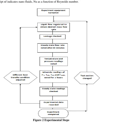
METHODOLOGY AND EXPERIMENTAL MEASUREMENT
The present work is undertaken to study the following aspects of• To ascertain the effectiveness of the Computational Fluid Dynamics analysis.
• Sensitivity study of micro-channel
• Computational Fluid Dynamics modeling and simulation of single phase micro-channel heat exchanger to
understand its hydrodynamic and thermal behaviour.
• Computational Fluid Dynamics models by comparing the present simulated results with the data available
in the open literature.
Hypothesis Formulation
The following assumptions are made to model the heat transfer in the consider channel: (1) Steady state
(2) Incompressible fluid (3) Laminar flow
(4) Constant fluid properties
(5) Negligible axial conduction and viscous dissipation, and negligible radioactive and natural convective heat transfer from the micro-channel heat sink.
The heat flux is commonly stated as
q
''rIV
LW
Here, V and I denote the voltage and current delivered fromthe power supply, respectively and, L and W present the overall channel length and channel width, respectively.
The heat transfer coefficient is calculated from the following equations nf nf
,
nfnf w f
h D
q
Nu
h
k
T
T
.Where subscript nf indicates nano fluids, Nu as a function of Reynolds number.
3.1 Heat Sink Model
A typical parallel plate heat sink considered in this present work is shown in Fig.3. The important geometric variables considered are fin height , fin thickness , base height and fin pitch.
Fig.3: A typical heat sink
A typical computational model of the parallel plate heat sink created in Gambit is shown in Fig. 4.
Fig.4: Computational model Governing Equations of Fluid Flow:
The most general form of fluid flow and heat transfer equations of compressible Newtonian fluid with time dependency used in solver execution is given as follows: Mass :
X – momentum :
Y – momentum :
Z – momentum :
Energy :
Equation of state:
where ρ is the density, u,v and w are velocity components, V is the velocity vector, p is the pressure, S terms are the source terms and τ terms are the viscous stress components which are defined for a Newtonian fluid as.
Here,μ is the dynamic viscosity, Ф is the viscous dissipation term and λ is the second viscosity and a good approximation for gases
λ = - 2 μ 3
This dissipation term is usually very small except for high Mach number flows. Here,
h is the total enthalpy, which is defined as where he is the enthalpy defined as
where he is the enthalpy defined as he =TTREF CP dT
i is the internal thermal energy, E is the total energy of the fluid which is the sum of internal thermal energy and kinetic energy.
The range of geometric parameters of the chosen heat sink for the present study is given in Table 1. Considering the various geometric variables present, 81 models are created in gambit and simulation are carried out using Fluent to determine the output parameters like base temperature, pressure drop.
Table 1. Range of geometric parameter
i is the internal thermal energy, E is the total energy of the fluid which is the sum of internal thermal energy and kinetic energy.
3.2 CFD Simulations
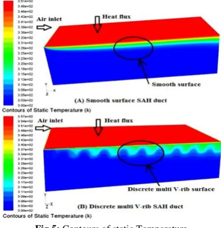
In the modeling and simulation, three levels in these input geometric parameters are chosen such that the differences are large enough to measure changes in the responses. If the levels are too close to each other, the change might not be large enough to detect and the opportunity for optimization could be lost. If the levels are too far apart, the design space of interest may not be able to be optimized due to non-linear or discontinuous response between the values. The simulations are carried out using fluent software with air flow at 25 CFM and a heat input of 100 W at the heat sink base. A typical temperature distribution in heat sink simulated using Fluent is shown in Fig. 4
Fig.5: Contours of static Temperature Parameter
Minimum value
Maximum value
Increment value Fin Height
(H) 14mm 48 mm 16
FIN THICKNESS
( T ) 0.8 mm 1.6 mm 0.4
Base Height
( BH) 4 mm 12 mm 4
FIN PITCH
3.3 Heat sink model Validation
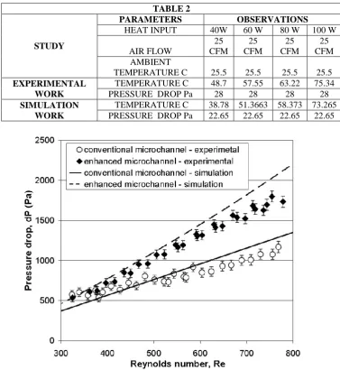
Experimental studies have been carried out with a parallel plate heat sink. These results obtained are compared with the simulation results. The experimental and simulation results are given in table 2 and are found identical in nature within acceptable limit of deviations
Figure 6:. Comparison between Pressure drop dp and Re
Figure 7:. Comparison between Nu and. Re among empirical correlation and experimental data. TABLE 2
STUDY
PARAMETERS OBSERVATIONS
HEAT INPUT 40W 60 W 80 W 100 W
AIR FLOW
25 CFM
25 CFM
25 CFM
25 CFM AMBIENT
TEMPERATURE C 25.5 25.5 25.5 25.5
EXPERIMENTAL WORK
TEMPERATURE C 48.7 57.55 63.22 75.34
PRESSURE DROP Pa 28 28 28 28
SIMULATION WORK
TEMPERATURE C 38.78 51.3663 58.373 73.265
Table 3
Nu SAMPLE1 1 SAMPLE2 2 SAMPLE3 3 SAMPLE4
10 0.2 0.4 0.3 0.45
20 0.4 0.6 0.8 0.9
30 0.6 1 1.3 1.4
40 0.8 1.4 1.5 1.6
50 1 1.5 1.6 1.8
60 1.2 1.6 1.7 1.9
70 1.4 1.7 1.8 2.2
It is also noted that high temperature gradients at the inlet and exit were observed from the temperature distributions of micro channels for all sets of the test specimens. In addition, the Nusselt numbers increase as the Reynolds number increases, as shown in Fig.9. For the range of the Reynolds number being tested (Re > 50), the average discrepancy of the values calculated from the correlation of Nu obtained in [13] and those obtained from the experimental data is within 19%; the difference is judged to be in fair agreement.
IV.
RESULTS AND DISCUSSION
In this exploration work, ideal plan of the warmth sink have been completed on a parallel plate warm sink considering the geometric parameters, for example, balance tallness , balance thickness , base stature and blade pitch with a consistent length and width of a warmth sink utilizing computational fluid dynamics think about. The reproduction is completed with the Commercial programming gave by familiar Inc. Trial contemplates have been done with a parallel plate warm sink to approve the warmth sink display. The outcomes acquired in the trial contemplates have been contrasted and the recreation results and observed to be in great understanding.
These results and conclusions drawn in this present work are found to be in good agreement with conclusions drawn by Lee (1995), and C.W. Leung and S.D. Probert (1988). This study will benefit the design engineers involved in electronic cooling. Using the approach presented in this research work, the design engineers can carry out optimization of parametric CAD models, for the selection or design of heat sink for effective thermal management in their electronic assemblies.
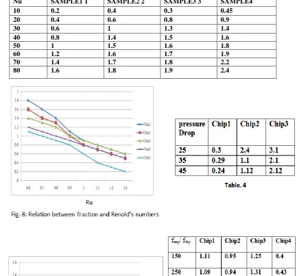
To analyze the friction factor, the specifications of the sink are listed in Table 4. Chip 1−4 are prepared for fluid flow experiment. Figure 8 shows the relations between the friction factor and the Reynolds number. This denotes to be the laminar flow and the friction factor is decreasing with the power of Reynolds number. The computed value of fexp/fthy ranged from 0.8 to 1.4 is shown in Figure 9, which matches the range of
1.0−1.6 byMohiuddin-Mala [14].
Table1 shows the different microchannel geometries are selected for the heat transfer experiment. The results are shown in Figure 6 and 7. In Figure 6, it is observed that the phenomenon of decreasing wall temperature during phase change is the same as Peng and Wang [18].
Figure 6 & 10, shows the relation between the inlet/outlet pressure drop and the wall temperature. It is observed to have two sections, the two phase section and the phase transformation section. In the single-phase section, the pressure drop between the inlet and outlet is obviously reduced with the wall temperature rises as the hydraulic diameter gets smaller. This is because of the viscosity coefficient of working fluid decreases with the temperature.
When the channel wall temperature reaches the critical point for phase change, the fluid rapidly absorbs the accumulated energy on the channel for the violent nucleate boiling. Therefore, the tiny bubbles are formulated to sharply increase the pressure drop. After the severe nucleate boiling, the wall temperature greatly decreases and boiling phenomenon decelerates and the inlet/outlet pressure drop diminishes. Finally, the wall temperature grows again and much severe nucleate boiling follows to continuously boost the pressure drop.
It is also observed with flow visualization that there exists the nucleate boiling at the channel inlet. This retards the fluid flow and the pressure drop is thus suddenly enlarged. From Figure 10, it is noted that the result for Chip 3 is different from others. The channel temperature hardly decreased from the phase change, the heat transfer coefficient barely reduced from the high channel wall temperature, and the inlet/outlet pressure drop did not rapidly diminish from the severe nucleate boiling.
Therefore, it is found that the nucleate boiling occurs between Chip1 and Chip3. With this viewpoint, the critical bubble size of methanol is recognized to be in between 56−85 μm.
V.
CONCLUSIONS AND FUTURE WORK
Experimental tests and theoretical analyses are conduct to investigate the characteristics of fluid flow and heat transfer in micro-channel heat sink in this work. Methanol are use as the working fluid and flow through micro-channels with different hydraulic diameters ranging from 57−267 μm in the experiments we examined the experimental results of flow characteristics & check behavior of the laminar regime when Re = 50−850, the phenomena of transition exist or not.
This work is the experimentally studies the characteristics on both fluid flow and heat transfer of methanol in the (100) silicon micro-channel heat sink. This study would surely contribute a valuable approach to the micro cooling technology for solving the heat dissipation of precision and compact electronic components. The potential of developing combined V- shaped wavy lower plate with methanol as cooling using various particle volume fractions and base fluids in enhancing the heat transfer, the following finding scan be drawn: 1. The computational result successfully validated the test data in terms of wall temperature distributions,
pressure drop of the channel and friction factor.
2. Pressure drop increases as Reynolds no. increases. Increasing nanoparticle concentration increases two- phase pressure drop compared to pure fluids at the same Reynolds number
3. Greater heat transfer coefficient is obtained at micro channel entrance 4. Wall temperature increases from entry region of micro channel to exit region.
5. Micro channel heat sinks dissipate large amounts of heat with relatively little surface temperature rise. 6. As Reynolds number increases; the heat transfer coefficient, pressure drop and pumping power increases
while thermal resistance and friction factor decreases.
7. To enhance the heat transfer in micro channel heat sink, it is necessary to study simultaneous effects of various parameters like size of channel, shape of channel, fluid properties, Reynolds number, friction factor, pressure drop, pumping power etc.
8. In the micro channel, the local heat flux q’’ varies with the channel size, cross section of channel, shape of channel, fluid properties and the fluid flow arrangement.
9. It is found that the experimentally determined Nusselt number in micro channels is lower than that predicted by the theoretical analysis.
ACKNOWLEDGEMENT
The researcher would like to thank the honourable Vice chancellor of IFTM University, Moradabad for providing the necessary facilities and permission to carry out this research work. The authors also wish to acknowledge the research group of Physics Lab, School of Sciences, IFTM University for their constant help to complete this work.
NOMENCLATURE L: overall channel length (m) W: channel width (m)
Dh: hydraulic diameter of the microchannel (m) ΔP: pressure drop between inlet and outlet (pa) ρf: density of working fluid (kg/m3)
Vf: velocity of working fluid (m/s)
ΔPloss: pressure loss between inlet and outlet (pa) fthy: theoretical friction factor
fexp: experimental friction factor
I: current delivered from the power supply (Amp) V: voltage delivered from the power supply (volt) gc: unit change factor (1.0 kg m/N s2)
K: pressure loss coefficient q″: heat flux (W/m2) γ: mended factor Nu: Nusselt number Re: Reynolds number Pr : Prandtl number
Wb : Bottom width of trapezoidal microchannels Wt :Top width of trapezoidal microchannels H : Microchannel height, m
Surface roughness, m
KL: Friction factor for minor loss
: Density, kg m-3
REFERENCES
[1]. Mark E. Steinke, Satish G. Kandlikar, Single-Phase Liquid Heat Transfer In Plain And Enhanced Microchannels, Proceedings of ICNMM2006 Fourth International Conference on Nanochannels, Microchannels and Minichannels June 19-21, 2006, Limerick, Ireland.
[2]. Bianco, V., Chiacchio, F., Manca, O. and Nardini, S. 2009. Numerical investigation of nanofluids forced
convection in circular tubes. Applied Thermal Engineering, 29 (17-18), 3632–3642.
[3]. Peng, X. F., Wang, B. X., Peterson, G. P., and Ma, H. B. 1995. Experimental investigation of heat transfer in flat plates with rectangular micro channels. International Journal of Heat and Mass Transfer. 38,127-137.
[4]. Peng, X.F. and Peterson, G.P., 1996. Convective heat transfer and flow friction for water flow in micro
channel structures. Int. J. Heat Mass Transfer. 39 12, 2599–2608.
[5]. H.Y. Wu, P. Cheng, An experimental study of convective heat transfer in silicon microchannels with different surface conditions, International Journal of Heat and Mass Transfer 46 (2003) 2547–2556. [6]. H.Y. Wu, P. Cheng, Friction factors in smooth trapezoidal silicon microchannels with different aspect
ratio, Int. J. Heat Mass Transfer.
[7]. X.F. Peng, G.P. Peterson, Convective heat transfer and flow friction for water flow in microchannel structures, Int. J. Heat Mass Transfer 39 (12) (1996) 2599–2608.
[8]. Fedorov, A. G. and Raymond, V. 2000. Three-dimensional conjugate heat transfer in the micro channel
heat sink for electronic packaging. International Journal of Heat and Mass Transfer. 43 399-415.
[9]. Flockhart, S. M., and Dhariwal, R. S., 1998, “Experimental and Numerical Investigation into the Flow Characteristics of Channels Etched in _100_ Silicon,” ASME J. Fluids Eng., 120, pp. 291–295.
[10]. Kawano, K., Minakami, K., Iwasaki, H. and Ishizuka, M. 1998. Micro channel heat exchangerfor cooling
electrical equipment. Appl. Heat Transfer Equip., Syst. Educ. ASME HTD-361-3/PID-3, 173-180. [11]. Tuckerman, D.B. and Pease, R.F. 1981. High-performance heat sinking for VLSI. IEEE Electronic
Devices Letters. EDL-2, 5, 126-129.
[12]. Yu-Tang Chen1,2, Shung-Wen Kang1, Wen-Chian Tuh1 and Tsung-Hsin Hsiao1Tamkang Journal of
[13]. Yang, W. J. and Zhang, N. L., “Micro- and Nano-scale Heat Transfer Phenomena Research Trends,” Transport Science and Technology, pp. 1−15 (1992).
[14]. Mala, G. M. and Li, D., “Flow Characteristics of Water in Micro Tubes,” Int. J. Heat and Fluid Flow, Vol. 20, pp. 142−148 (1999).
[15]. Jiang, L., Wong, M. and Zohar, Y., “Phase Change in Microchannel Heat Sinks with Integrated Temperature Sensors,” J. of Microelectromechanical System, Vol. 8, pp. 358−365 (1999).
[16]. Naphon P, Kornkumjayrit K. Numerical analysis on the fluid flow and heat transfer in the channel with
V-shaped wavy lower plate. Intl Commun Heat Mass Transf (2008) ;35:839–43.
[17]. Singh , A.P. Siddiqui, Mohd. Ghufran Ali , An Experimental and Numerical Investigation of Fluid Flow
and Heat Transfer in Different Micro-channels, IJSRSET, Vol. 4 (4), p-1274-1283, (2018).
[18]. Peng, X. F., Peterson, G. P. and Wang, B. X., “Heat Transfer Characteristics of Water Flowing through
Microchannels,” Experimental Heat Transfer, Vol. 7, pp. 265−283 (1994).
[19]. Copeland, D. (2000). “Optimization of parallel plate heat sinks for forced convection”,IEEE Semiconductor thermal measurement and management symposium, San Jose, USA, March, pp266-272.
[20]. Park, Park-Kyoun Oh, Hyo-Jae Lim (2006), “The application of the CFD and Kriging method to
an optimization of heat sink”, International Journal of Heat and Mass Transfer 49 3439–3447
[21]. Culhamand J. R and Muzychka Y. S (2001), “Optimization of Plate Fin Heat SinksUsing Entropy
Generation Minimization”, IEEE transactions on components and packaging techno- logies, vol. 24,
no. 2, June PP 159 –165