Sharif University of Technology
Scientia IranicaTransactions B: Mechanical Engineering http://scientiairanica.sharif.edu
Dynamic adaptive mesh renement of uid-structure
interaction using immersed boundary method with
two-stage corrections
M.S. Aldlemy
a,b;, M.R. Rasani
a, T.M.Y.S. Tuan
c, and A.K. Arin
aa. Department of Mechanical and Materials Engineering, Faculty of Engineering and Built Environment, Universiti Kebangsaan Malaysia, 43600 Bangi, Selangor, Malaysia.
b. Department of Mechanical Engineering, Collage of Mechanical Engineering Technology, Benghazi-Libya.
c. Department of Mechanical Engineering, Faculty of Engineering, Universiti Teknologi Petronas, 31750 Tronoh, Perak, Malaysia. Received 26 January 2018; received in revised form 6 April 2018; accepted 7 July 2018
KEYWORDS Two-stage correction; Fluid-structure interaction;
Immersed boundary method;
adaptive mesh renement.
Abstract. The application of the Immersed Boundary Method (IBM) coupled with Adaptive Mesh Renement (AMR) is considered to be one of the powerful tools for solving complex viscous incompressible ow problems. In this paper, the Kajishima-cut-cell IBM is combined with AMR to solve the ow of complex incompressible, viscous uid, and rigid body problems. In the IBM, the solid and uid motions at the interface are controlled by a body force that can be calculated with a fraction of solid volume. The objective is to develop an automatic adaptive mesh renement strategy to enhance the solution in proximity to the uid-structure interface. This is necessary as the ow eld might be signicantly aected by the structure boundaries; therefore, it is essential to capture the boundary layers precisely. The capability of this method can be demonstrated through computational results to improve the ow resolution near the uid structure. The proposed approach is validated using a 2D laminar ow numerical example. The approach is validated in terms of accuracy and performance. The combined IBM-Adaptive mesh renement approach showed a promising outcome for the investigated problem. The result of the implemented method achieved an acceptable error performance within a reasonably low computation time.
© 2019 Sharif University of Technology. All rights reserved.
1. Introduction
In multi-physics, the Fluid-Structure Interaction (FSI) is a vital, yet challenging, phenomenon that plays a signicant path in several engineering and scientic studies. The interaction between a ow eld and a deformable or moveable structure is considered in this regard [1]. It is an essential aspect in several
engineer-*. Corresponding author. Tel.: +601114298808 E-mail addresses: [email protected] and [email protected] (M.S. Aldlemy)
doi: 10.24200/sci.2018.50347.1650
ing applications such as bridges, aircraft wings, airbags, turbine blades, and tent roofs. It is also applicable to biological systems such as blood circulation through the vascular system, the movement of air through the pulmonary system, cellular immersion, and the movement of some sh in water [2,3]. It is usually a tough task to develop analytical solutions for modeling FSI problems due to their complex nature. It is also not always easy to conduct experiments on specic problems due to the high cost and the scarcity of the required facilities. Numerical simulations are often considered as a solution to complex problems when investigating the basic phenomenon involved in uid-structure interactions [4,5]. Numerical simulations are
usually supported by experimental results in many sci-entic and engineering elds, thereby eliminating or re-ducing the need to carry out several experiments. The development of ecient numerical methods and their application for solving complicated FSI problems have attracted much research attention over the years [6,7]. FSI problems can be modeled using a structural mesh, which shares the same attributes with the uid mesh, or they can be modeled using a structural mesh that bears no structural resemblance to the uid mesh [2,8,9]. The domain and boundaries in the structural mesh approach often change because they follow the path of the interface structure deformation. This requires the use of an Arbitrary Lagrangian-Eulerian (ALE) approach to FSI. Total remeshing or mesh deformation for the whole uid domain is needed, which requires a reasonable computational eort [10].
In a case where the structural mesh does not conform to the uid mesh, the Eulerian approach is applied to formulate the xed uid grid [7]. This approach is advantageous in that it does not need to continuously update the mesh for the domain. Within this scheme, many approaches have been developed such as the eXtended Finite Element Method (XFEM), which enforces uid-structure interactions using La-grangian multipliers [11], a ctitious domain/mortar element method [12], the Immersed Boundary Method (IBM), which interpolates the variables between the uid and structure using smoothed Dirac-delta func-tion domains [13-15], and the Immersed Finite Element Method (IFEM), which, unlike the IBM method, inter-polates the interfacing velocities and body forces using a reproducible kernel particle method [16].
The concept of the IBM was rst put forward by [17], in which the impacts of moving boundaries were considered as an external force in the formulation of uid motion. This was used to satisfy the case of no-slips on the solid boundaries. In another study, the same author and his collaborators developed a deformable thin object that was incorporated into the IBM approach [18,19]. IBMs are categorized according to the method of imposing the boundary conditions on the interface. The continuous forcing approach in IBM is normally used for ows that possess immersed elastic boundaries [20]. However, applying this approach to ows with rigid bodies can generate few diculties. The cut-cell approach in IBM suers from uctuations in the calculated value of the pressure.
The uid structure interaction force in Ka-jishima's method is modeled using the relative veloci-ties of the phases and a fraction of the solid volume [21]. In this method, there is no loss of momentum because the solid and the uid share the rectilinear Eulerian grid, thereby ruling out the possibility of interpolation. The variation in the velocity eld because of the average volume of the local solid and uid velocity
aects the continuity. The uid structure interaction in Kajishima's method is coupled with the body force. The inaccurate resolution of the ow near the moving structures is a major disadvantage of the xed grid approach [22].
The AMR algorithm has been predominantly utilized in the eld of uid-structure engineering as it is procient in solving nite element linear and non-linear formulations [23-26]. Based on the AMR concept, a rectangular space was developed by properly nesting grid patches to account for those regions that have steep gradients in the solution, while preserving an acceptable level of error with minimum consumption of time. The adaptive mesh renement method con-centrates on rening certain mesh zones based on the dynamic characteristics of the ow to achieve a suitable grid resolution for any part of the domain [27,28]. This method is benecial because it is an automatic and dynamic mesh adaptation system that solves ow issues accurately [20]. The xed mesh construction needs the establishment of the maximum grid resolution in zones that may not be needed for simulation right from the start of the simulation. Most recently, several scholars have established a number of ndings in this eld. A parallel scheme of an adaptive renement mesh was investigated for the AMSS-NCKU problem [29]. A stabilized IBM approach, developed for compressible Navier-Stokes equations, was studied by [30]. Another study by [31] was based on GPU-accelerated AMR for the IBM. However, to overcome existing drawbacks, the study is still in the process of developing new methods such as a simple computational process or accurate numerical outcomes.
The interpolation function determines the inter-action between the structure and uid and, also, shapes the space between the structure and uid interface within the width of the mesh of the uid grids. It is, however, dicult to capture the resolutions of the boundary layer near the structural surface without using structural body-aligned boundary layer meshes. The disadvantages explained above inspired the de-velopment of a numerical technique depending on the integration of adaptive mesh renement with IBM in a monolithic FSI method, which can solve the interaction problem between a viscous uid and a rigid body.
In this research, the Fractional Step Method (FSM) can be used to solve the pressure eld problem for the thin uid-solid-interface boundary layers. The equations of motion are implemented in an AMR scheme to achieve a solution that can eciently capture the structure of ows from such interfaces. This is necessary due to the possibility that the structure can aect the ow eld signicantly; therefore, it becomes necessary to detect and capture the boundary layers accurately. The applicability of the approach was tested by applying it to 2D ow elds with a rigid
body. A benchmark two-dimensional computational problem has validated the eectiveness of the developed formulation.
2. Governing equation and numerical methods 2.1. Basic governing equations
The Navier-Stokes (N-S) equations are the governing equations and can be described as given below:
r:uf = 0; (1)
uf
t +uf:r:uf= 1
frp + vfr:
ruf+(ruf)T; (2)
where uf represents the velocity of uid, p reects
the pressure, f is the uid density, and vf is the
uid kinematic viscosity. The Eulerian variables were arranged by the Cartesian grid. Eqs. (1) and (2) were determined via a second-order nite dierence method in space and time. Regarding the cells that were partly occupied by the solid structure, the exchange of momentum at their uid-structure boundary was proposed to be solved by the IBM method. A brief discussion of this method is presented in the next section.
2.2. Fluid-solid interaction model and numerical implementation
The IBM method was successfully used to solve the exchange in momentum at the uid-solid interface for cells partially occupied by intruders [21]. Briey, for this method, a velocity eld was introduced at the solid-uid interfaces, where the cells were partially lled with solid particles and solved using the IBM. The velocity eld was introduced by averaging the volume of the local, uf, and solid up velocities in each cell.
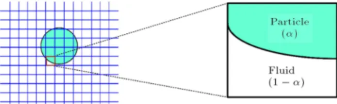
u = (1 )uf+ vp; (3)
where (0 1) represents a fraction of the cell solid volume, as presented in Figure 1. The particle velocity, up, can be separated into rotating and
translating components as up = vt+ r !p. The vt
is the objects' translating velocity, !p is the objects'
angular velocity, and r is the relative position of the object from the centre of gravity to a point within the integral region. The volume fraction is evaluated using the following hyperbolic tangent function:
= 1 2
1 tanh
s
; (4)
= jnxj + jnyj; (5)
= 0:05(1 2) + 0:3; (6)
Figure 1. Fluid-solid volumetric fraction for uniform Cartesian cells.
where n = (nx; ny) is the normal outward unit vector of
the surface element, while s is the distance from the
elements' central surface. The indicated formulation, called the surface digitizer, was proposed by [32]. Here, the uid and object interaction could be determined at the interface in the case where the velocity eld is in adherence to N-S equations:
@u @t =
1
frp + Hu+ fp; (7) Hu= u:ru + vfr:ru + (ru)T: (8)
The following scheme is presented for time advance-ment for u:
un+1= u
I tf1 rp + tfp; (9)
uI = un+ t
3
2Hun 12Hun 1
; (10)
fp= (uptuI); (11)
where t is an increase in time, while fpis the intruder
eect on the uid inside the object at the interface. It is worth noting that at = 0 with zero interaction force, fp= 0 is implemented.
On top of that, a second order in accordance with the method presented by Adam Bashforth pertaining to single-phase uid is employed to dene time ad-vancement. The same force, as in Eq. (11), with a reversal sign is applied to the particle fraction in the cell. The body force replaces the hydrodynamic tension at the interface, while the particle phase advancement is completed through the integrated force over the particle volume. Since pressure has been applied to couple the uid-structure interaction, the numerical schemes are modied. The body force, fp, is eliminated
from Eq. (7). The following equation reects the eld of velocity in adherence to N-S equations:
@uf
@t = 1
frp + Hu; (12) Hu= uf:ruf+ vfr:ruf+ (ruf)T: (13)
The following portrays the scheme for time advance-ment uf:
uI = unf+ t
3 2Hun
1 2Hun 1
; (14)
1
fr2pn+1= r:uI
t ; (15)
un+1
f = uI tf1 rpn+1; (16)
where u represents the time, uI denes the
interme-diate velocity, and t exhibits the increment of the time. Here, the Adam-Bashforth approach is used to determine the time advancement.
2.3. Two-stage correction of velocity and pressure
The main idea explained in Eq. (3) involves the solid object being subject to interaction enforcement. There-after, the pressure changes were derived. Owing to the fact that the results of the rst-order derivation are not corrected with the interaction force enforcement, a second derivation was performed at the aected cells. A small area near the object was selected to correct u in Eq. (3), as denoted by un+1
2 . In addition, the Simplied
Marker and Cell (SMAC) approach was applied to determine the scalar value for the correction of pressure and velocity so as to gain un+1
3 , and pn+12 . In this case,
the method of projection was employed to rectify the pressure close to the object surface [33]:
1
fr2n+1=
r:un+1 2
t ; (17)
un+1
3 = un+12 tf1 rn+1; (18)
pn+1
2 = pn+11 + n+1; (19)
where un+1
3 and pn+12 are velocity and pressure, which
satisfy the equation of continuity for the following time step.
3. Adaptive mesh renement
In recent times, most algorithms used for integrating hyperbolic equations are equipped with mesh rene-ment in several ways. The presence of small-scale features and discontinuities in the hyperbolic equations has demanded the application of numerical algorithms to ne meshes with, ideally, smaller scales, compared to those to be solved. On the contrary, an increase in the demand for the computational uid dynamic capabilities has necessitated the development of algo-rithms on ne meshes with high-order methods. The
computational cost of such issues, including parallel computers, is a major drawback of these methods.
Adaptive mesh renement based on the grid adap-tation technique was rst introduced by [28]. The AMR algorithm does not require a considerable decrease in the number of grid cells, but a decrease in the entire number of integrations in the algorithm. Accordingly, this algorithm takes much operational time, partic-ularly for those high-resolution and shock-capturing schemes. AMR can be dened as a combined adaptive method and is two-fold in that an arbitrary grid reso-lution is allowed by dening a set of overlapping grids through multiple resolutions. For each resolution, the grid hierarchy level is dened only for such a resolution in the part of the foreseen domain. The manner of grid overlapping allows for time renement, such that, in each grid, there is a temporary step appropriate for its spatial size. To maintain the accuracy and stability of the grids, the time allocated to the grids corresponds to the actual size of their smallest cells. If grids with mixed cell sizes are considered in isolation, coarser cells with bigger time steps could be evolved; however, since, at every iteration, each cell associated with the grid needs to be equally evolved simultaneously, the time step is xed in the grid for each cell [34]. In the AMR algorithm, ne cells are allowed to evolve with shorter time steps when compared with coarse cells. They are grouped into independent grids, where each group of cells has the same size.
3.1. Zonal grid renement and hierarchical renement
The use of adaptive schemes has been the rst idea for improving the solution near uid-structure interfaces. This is important because the ow eld may be aected by the structure, and it is also necessary to capture the boundary layers accurately. The computations in this paper have been conducted based on the concept of adaptive mesh renement, which involves the interpo-lation of nodes into smaller versions. This approach has been developed by computing the stationary ow around a cylinder with a very thin mesh renement layer. Nodes at intervals of X = 0:1 are used to build the initial uid mesh; the nest nal mesh is 80 80(6400) with x = 0:00125 of uid nodes mesh. The renement level in each step along the implicit interface was increased by one. In summary, a generally applicable method for improving the accuracy of xed grid methods is possible with the nest adap-tive mesh renement surrounding the cylinder. The application of an automatic renement supports xed grid methods, which do not support many structural movement predictions. Meanwhile, mesh updates could be frequently conducted in accordance with the implicit interface for transient issues associated with large structural surface movements. It would be benecial
Figure 2. AMR for 2D. Renement is achieved by creating rectangular grid patches with renement. A ner resolution mesh is applied each time.
in such cases to have a small uid element layer along the surface of the structure to always keep an optimal boundary layer mesh.
Furthermore, the time variable is considered in accordance with the level of renement. Mathemati-cally, the time step integration can be expressed in the following term Lev;k k = 1; :::; pLev, in which pLev
represents the total number of patches that correlate with the cell size. A synchronization procedure is developed for time step integration among the solution levels. In Figure 2, the grid patches are adjusted in accordance with coarser grid lines or with the rectangular domain boundaries.
There is always a transfer of Eulerian quantities taken to the new hierarchy from the old grid hierarchy; a grid hierarchy is interpolated each time. The rene-ment formula is x = X
2N , where x is the grid size of
the new node, X is the grid size of the old node, and N is the discretizing step. The force densities can also be transported to a new hierarchy from the old one using conservative interpolation and coarsening operators. The uid pressure is linearly interpolated without any restrictions.
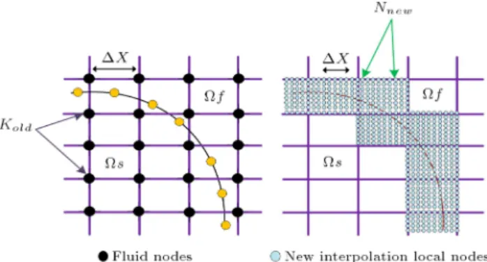
3.2. Interpolation on the adapted mesh
The interpolation of all variables at the node level from the old mesh is necessary since it is subject to time variability [35]. This very simple procedure involves the use of a linear interpolation approach, as shown in Figure 3. During the rst stage, an initial node, Kold,
is located \in the rectangular grid of Cartesian" and, then, the new node, Nnew, is generated for the new
mesh. The quantity Nnew is obtained here through the
local representation regarding Kold. Thus, the level set
function is anticipated in the continuous space as an advanced step to the interpolation procedure. Kold is
located by a particular procedure. The primary node, N1new, is located through a one-dimensional search in
Figure 3. Eulerian and Lagrangian meshes: (left) Fluid-solid interface and (right) computation of interpolation coecients from locally renes mesh.
accordance with the K1old node, in which the search
direction is attained through a steep descent algorithm. This is followed by the interpolation of the second node, N1new, which boards onto the node, N1new.
On the other hand, in searching for the consequent K2old initiated from K1old, this process is performed
repeatedly untill the entire new nodes are positioned onto the old mesh. The features of the computational cost regarding search algorithm scales are linear, with N representing the new mesh's nodal number.
A well-known feature of IBM is that the grid lines are not aligned with the surface of the object [13]. Hence, the goal of the immersed boundary method is to estimate the space by assuming that the incompressible solid surface has elastic or visco-elastic properties, as shown in Figure 3. This gure shows that the developed mesh renement procedure is mostly similar to the generated software modeling, except that the proposed method is simpler and more exible [36,37]. 3.3. Grid coupling of AMR algorithm and
IBM
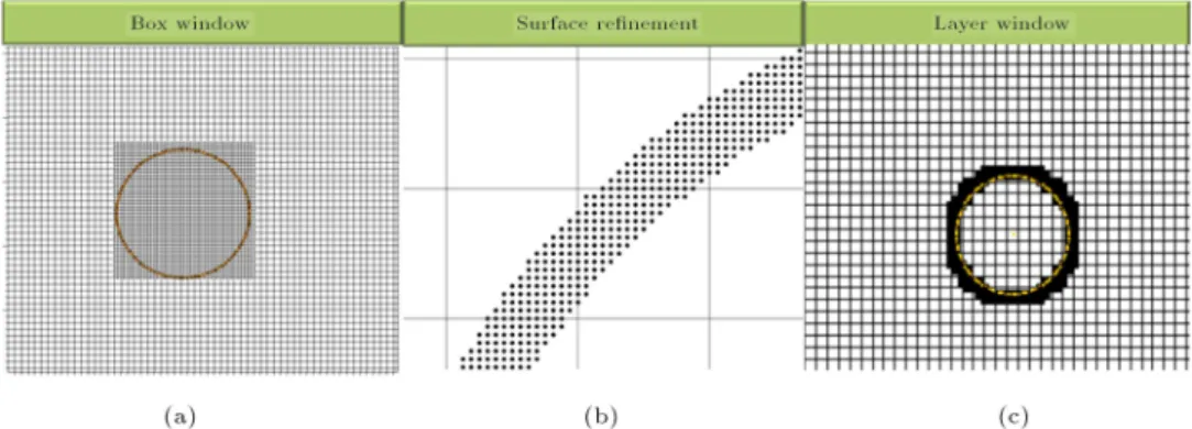
Figure 4. Examples of user-input keywords for local mesh renement.
Algorithm 1. Monolithic AMR and IBM rened approach within a one-time step.
to control the local resolution in order to generate meshes. Examples of this study are presented in Figure 4. Figure 4(a) shows a box window that enforces the prescribed mesh resolutions inside a box, while Figure 4(b) shows the surface renement that enforces the prescribed mesh resolution along the surface of the solid body. Figure 4(c) indicates the layer window that enforces a prescribed mesh resolution away from the solid body. To achieve a desired mesh resolution near a solid in IBM, there must be surface renement. A smooth mesh transition from the boundary to the far eld can be achieved with a layer window. The method was developed in open-source software, written in FORTRAN language, and developed based on the Ubuntu 16.04 LTS operating system. The algorithm
can be visualized in greater detail (Algorithm 1). There is a need for optimized sequential, or even parallel, post-processors to manage large datasets that are generated in transient computations to visualize complex ows. One example of such a program is the VisIt 2.12.3 open-source code, which was employed in this work for the visualization of most of the 2D simulation results. This is a distributed, graphical analysis of and a parallel visualization tool for 2D dened meshes.
The locally rened mesh surrounding the solid is described in Figure 5. The main feature of this locally rened mesh surrounding the object is its dynamic movement, which does not require much computation since the determination is limited and does not include
Figure 5. Locally renes mesh for the cylinder. Table 1. Computational setup for cylinder benchmark. Parameters Initial mesh (A) Fine mesh (B) Number of grid point 220 41 80 80
Reynolds number UD= 100 100
Time increment, T 0.0005 0.000125
Grid size, x; y 0.01 0.0025
the entire domain space. The number of mesh points around the circular cylinder is approximately 6400 nodes with t = 0:000125 s.
4. Simulation setup
A two-dimensional cylinder benchmark background uid was used as the channel with a width of 2:2 m 0:41 m and a cylinder radius of 0.05, located at (0.2, 0.2). Moreover, prescribed to the channel is a parabolic inow with U = 1:5 m/s and `no-slip' boundary conditions pertaining to the lower and upper maximum velocities of U max x walls. The density for the kinematic viscosity was set at f = 1:0 kg/m3. The
Reynolds number obtained was 100 according to the benchmark. For the rened mesh zone, 0:2 m 0:2 m is used, the time increment is 0.000125, and grid size is x; y = 0:0025. Table 1 displays all details of the simulation setup.
Benchmark code validation
The benchmark research by [38] is recalled here in order to validate the functionality of the developed approach. The numerical value of the laminar ow over a cylinder is equal to 100. The value of the stationary ow in a two-dimensional case with a diameter D and at dierent Reynolds numbers has been calculated via Re = UD=. For this type of computational modeling, the drag coecient, Cdrag, and lift coecient, Clift,
form the interaction simulation. The mathematical formula can be expressed in the following two forms: Cdrag = U2F2D
mD and Clift =
2FL
U2
mD. Both coecients
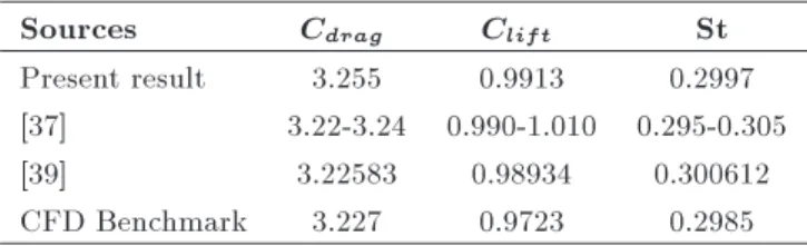
were determined through the integration of the IB force with respect to the Lagrangian space. In addition, the Strouhal number St = Df= U was also computed to validate the cylinder-uid interaction simulation. The pressure was sourced from the uid node nearest to the cylinder surface using the described method by employing pressure retrieval. Table 2 shows the result of the lift coecient and pressure drag coe-cient against Re = 100. Two batches of results are achieved through the IBM using the rigid cylinder and OpenFOAM-5.0 software. The drag coecient (Cdrag), lift coecient Clift, and St from the IBM are
shown to be in agreement with the results obtained by the OpenFOAM-5.0 software and with the referenced results.
Table 2. Flow around stationary circular cylinder: CD, CL, and St for Re = 100.
Sources Cdrag Clift St
Present result 3.255 0.9913 0.2997 [37] 3.22-3.24 0.990-1.010 0.295-0.305
[39] 3.22583 0.98934 0.300612
5. Numerical results and discussion
The aim of this work is to develop a mesh rene-ment technique that is suitable for the interaction of deformable, compressible or incompressible struc-tures with incompressible ows subjected to severe deformations in order to solve FSI problems. The proposed FSI method enjoys two main features: rst, it can handle complex and unlimited structural de-formations and, second, a proper mesh resolution is preserved around the surface structure that is initially constructed throughout the simulation. These features characterize the proposed method best, making it a proper approach for solving real-world FSI problems. This is further strengthened by the fact that where boundary layers usually exist, there is a layer of meshes where there can be ow separation and re-attachment as the prerequisites for achieving reliable results in the case of complex FSI problems.
In this section, the case of a uid moving over a solid cylinder using the proposed formulation is discussed. The examined example is a case proposed by [39]. The initial dimensional information provided is that of a rectangular uid domain with 2:2 m 0:41 m characterized by a cylindrical diameter of 0.1 m and positioned at (xc(t = 0); 0:22). The solid
cylinder surrounded by a ne layer of mesh is shown in Figure 6. The conguration of the developed model for the mesh renement has been compared with the benchmark model using OpenFOAM-5.0 software. The visualizations of the two graphs demonstrate that the mesh renements are similar. The evolution of the lift coecient and drag coecient at Re = 100 is demon-strated in Figure 7. The gure indicates noticeable agreement between the developed IBM-AMR algorithm and the comparable benchmark model for the lift and drag coecient over the time-history of the simulation. The implementation of the developed technique exhibits a very reliable and steady solution for both the pressure and velocity over time. The modeling also demonstrates a very satisfactory level of applicability for the value of the Reynolds number. The left, bottom, and top of the background uid subdomain boundary are set up at zero velocity. Hence, the
Figure 6. Final meshes used for comparison.
Figure 7. Time-histories of lift and drag coecients at Re = 100.
ow is xed and bound to the movement of the solid cylinder. The features of the uid include the viscosity of = 0:001 m2/s, Reynolds number equal
to 100, and a density of 1.0 kg/m3. Figure 8 shows
that the adaptive renement mesh for the stationary ow surrounding the cylindrical object is displayed in close visualization for the velocity and pressure indicators. Based on the graphical presentation of these two indicator components, the values are much similar to those determined through modeling using the commercial software, except that the employed algorithm (i.e., monolithic IBM renement approach with time step) is much simpler, does not require any high-level computations, and is not a time-consuming process. Based on the obtained results, a highly remarkable credit can be given to this algorithm for its wide ranging applications in the case of real-world FSI problems and their analyses such as compressive water ow in or out of pipes and air ow around aeroplane wings causing wing deformation.
The running time for the developed simulation is ve seconds with step sizes of one second. The results of the two-dimensional cylinder in terms of velocity and pressure were studied. Figures 9 and 10, respectively, illustrate the velocity and pressure elds in the x-direction. The main knowledge and advantage of the current research are that the mesh renement follows the movement of the object in the uid space dynamically, which is in contrast to state-of-the-art research [22]. Numerically, the inspected problem is validated with respect to the lift and drag coecient values, as well as the Strouhal number. Table 2 shows the obtained numerical values and compares them with those of the most reliable studies [38,40] and with the benchmark model.
The calculated computational time for the full renement mesh simulation is equal to 12531 seconds, although the computational time for the AMR simula-tion is equal to 1726 seconds, which represents less than 14% of the full computational time. The results show a very optimistic outcome in comparison to the
state-Figure 8. Visualizations of velocity and pressure adaptive renement for stationary ow around a cylinder. The renement IBM mesh is displayed in the close-up view: (a) Velocity and (b) pressure elds.
Figure 9. Moving cylinder with renement dynamic mesh: velocity (m/s) eld in x, y directions at dierent time steps.
of-the-art study and the benchmark model. However, the advantages of the present research are very simple in that it is less time-consuming and aordable.
6. Conclusions and remarks
The simulation of incompressible ows at moving boundaries in a very complex conguration was achieved through the integration of the IBM and AMR. In this paper, a new approach was developed to enhance the solution in proximity to the uid-solid
Figure 10. Moving cylinder with renement dynamic mesh: pressure eld at dierent time steps.
interface for two-dimensional problems. To this end, adaptive mesh renement was employed in simulation studies to increase the resolution as close as possible towards the solid interface. The time for the integra-tion of the governing equaintegra-tions was accelerated using a relatively coarse mesh with uniform background, which was deployed distant from the uid-solid interface. Due to the deformability of solid, it has become more desirable to use the AMR algorithm rather than a static body-tted meshing algorithm. The outcome of the current research exhibited a remarkable performance in comparison to the literature studies. The modeling
distinguished itself by its simplicity and shorter oper-ation time, compared to soft computing modeling. An extension can be made to new areas that require more resolutions or depend on the properties of the solver. For instance, a thin object analysis can be conducted, as stated in [40].
Acknowledgements
The authors would like to acknowledge the nan-cial support provided by Ministry of Higher Educa-tion (project grant code: FRGS/2/2013/TK01/UKM/ 02/2) and the assistance of resources provided at the facility in Faculty of Engineering and Built Environ-ment, Universiti Kebangsaan Malaysia.
References
1. Zhang, Q. and Hisada, T. \Analysis of uid-structure interaction problems with structural buckling and large domain changes by ALE nite element method", Comput. Methods Appl. Mech. Eng., 190, pp. 6341-6357 (2001).
2. Bungartz, H.J. and Schafer, M.Ed., Fluid-Structure-Interaction: Modelling, Simulation, Optimization, Springer Science & Business Media, 53 (2006).
3. Tezduyar, T.E., Sathe, S., Schwaab, M., and Con-klin, B.S. \Arterial uid mechanics modeling with the stabilized space{time uid{structure interaction technique", Int. J. Numer. Methods Fluids, 57(5) pp. 601-629 (2008).
4. Gebreslassie, M.G., Tabor, G.R., and Belmont, M.R. \Numerical simulation of a new type of cross ow tidal turbine using OpenFOAM - Part II: Investigation of turbine-to-turbine interaction", Renew. Energy, 50, pp. 1005-1013 (2013).
5. Zhong, J. and Xu, Z. \A reduced mesh movement method based on pseudo elastic solid for uid-structure interaction", Proceedings of the Institution of Me-chanical Engineers Part C: Journal of MeMe-chanical Engineering Science, 232(6), pp. 973-986 (2018).
6. Costarelli, S.D., Garelli, L., Cruchaga, M.A., Storti, M.A., Ausensi, R., and Idelsohn, S.R. \An embedded strategy for the analysis of uid structure interaction problems", Comput. Methods Appl. Mech. Eng., 300, pp. 106-128 (2016).
7. Farhat, C. and Lakshminarayan, V.K. \An ALE for-mulation of embedded boundary methods for tracking boundary layers in turbulent uid-structure interac-tion problems", J. Comput. Phys., 263, pp. 53-70 (2014).
8. Tezduyar, T.E., Sathe, S., Cragin, T., Nanna, B., Conklin, B.S., Pausewang, J., and Schwaab, M. \Mod-elling of uid-structure interactions with the space-time nite elements: Arterial uid mechanics", Int. J. Numer. Methods Fluids, 54, pp. 901-922 (2007).
9. Tezduyar, T.E. and Sathe, S. \Modelling of uid-structure interactions with the space-time nite ele-ments: Solution techniques", Int. J. Numer. Methods Fluids, 54, pp. 855-900 (2007).
10. Anahid, M. and Khoei, A. \Modeling of moving boundaries in large plasticity deformations via an enriched arbitrary Lagrangian-Eulerian FE method", Sci. Iran. Trans. A., J. Civ. Eng., 17, pp. 141-160 (2010).
11. Chessa, J., Smolinski, P., and Belytschko, T. \The extended nite element method (XFEM) for solidi-cation problems", Int. J. Numer. Methods Eng., 53, pp. 1959-1977 (2002).
12. Baaijens, F.P.T. \A ctitious domain mortar element method for uid-structure interaction", Int. J. Numer. Methods Fluids, 35, pp. 743-761 (2001).
13. Mittal, R. and Iaccarino, G. \Immersed boundary methods", Annu. Rev. Fluid Mech., 37, pp. 239-261 (2005).
14. Kim, J., Kim, D., and Choi, H. \An immersed-boundary nite-volume method for simulations of ow in complex geometries", J. Comput. Phys., 171, pp. 132-150 (2001).
15. Zhang, L., Gerstenberger, A., Wang, X., and Liu, W.K. \Immersed nite element method", Comput. Methods Appl., Mech. Eng., 193, pp. 2051-2067 (2004).
16. Peskin, C.S. \Flow patterns around heart valves: A numerical method", J. Comput. Phys., 10, pp. 252-271 (1972).
17. Zhu, L. and Peskin, C.S. \Simulation of a apping exible lament in a owing soap lm by the immersed boundary method", J. Comput. Phys., 179, pp. 452-468 (2002).
18. Zhu, L. and Peskin, C.S. \Drag of a exible ber in a 2D moving viscous uid", Comput. Fluids, 36, pp. 398-406 (2007).
19. Vanella, M., Posa, A., and Balaras, E. \Adaptive mesh renement for immersed boundary methods", J. Fluids Eng., 136, p. 40901 (2014).
20. Kajishima, T., Takiguchi, S., Hamasaki, H., and Miyake, Y. \Turbulence structure of particle-laden ow in a vertical plane channel due to vortex shed-ding", JSME Int. J. Ser. B., 44, pp. 526-535 (2001).
21. Wall, W., Gerstenberger, A., and Mayer, U. \Advances in xed-grid uid structure interaction", In: ECCO-MAS Multidisciplinary Jubilee Symposium, Springer, pp. 235-249 (2009).
22. Vanella, M., Rabenold, P., and Balaras, E. \A direct-forcing embedded-boundary method with adaptive mesh renement for uid-structure interaction prob-lems", J. Comput. Phys., 229, pp. 6427-6449 (2010).
23. Li, S. and Hyman, J.M. \Adaptive mesh renement for nite dierence WENO schemes", Los Alamos Rep, LA-UR- 03-8927 (2003).
24. Berger, M.J. and Leveque, R.J. \Adaptive mesh re-nement using wave-propagation algorithms for hyper-bolic systems", SIAM J. Numer. Anal., 35, pp. 2298-2316 (1998).
25. Li, S. \Comparison of renement criteria for structured adaptive mesh renement", J. Comput. Appl. Math., 233, pp. 3139-3147 (2010).
26. Berger, M.J. and Colella, P. \Local adaptive mesh renement for shock hydrodynamics", J. Comput. Phys., 82, pp. 64-84 (1989).
27. Berger, M.J. and Oliger, J. \Adaptive mesh renement for hyperbolic partial dierential equations", J. Com-put. Phys., 53, pp. 484-512 (1984).
28. Loer, F., Cao, Z., Brandt, S.R., and Du, Z. \A new parallelization scheme for adaptive mesh renement", J. Comput. Sci., 16, pp. 79-88 (2016).
29. Brehm, C., Hader, C., and Fasel, H.F. \A locally stabi-lized immersed boundary method for the compressible Navier-Stokes equations", J. Comput. Phys., 295, pp. 475-504 (2015).
30. Ji, H., Lien, F.S., and Zhang, F. \A GPU-accelerated adaptive mesh renement for immersed boundary methods", Comput. Fluids, 118, pp. 131-147 (2015).
31. Yuki, Y., Takeuchi, S., and Kajishima, T. \Ecient immersed boundary method for strong interaction problem of arbitrary shape object with the self-induced ow", J. Fluid Sci. Technol., 2, pp. 1-11 (2007).
32. Ya, T., Shah, T.M.Y., Takeuchi, S., and Kajishima, T. \Immersed boundary and nite element methods approach for interaction of an elastic body and uid by two-stage correction of velocity and pressure", In ASME/JSME 2007 5th Joint Fluids Engineering Conference, pp. 75-81 (2009).
33. Baeza, A., Martnez-Gavara, A., and Mulet, P. \Adap-tation based on interpolation errors for high order mesh renement methods applied to conservation laws", Appl. Numer. Math., 62, pp. 278-296 (2012).
34. Zheng, X., Lowengrub, J., Anderson, A., and Cristini, V. \Adaptive unstructured volume remeshing -II: Application to two- and three-dimensional level-set simulations of multiphase ow", J. Comput. Phys., 208, pp. 626-650 (2005).
35. Vanella, M. and Balaras, E. \A moving-least-squares reconstruction for embedded-boundary formulations", J. Comput. Phys., 228, pp. 6617-6628 (2009).
36. Kempe, T. and Frohlich, J. \An improved immersed boundary method with direct forcing for the simulation of particle laden ows", J. Comput. Phys., 231, pp. 3663-3684 (2012).
37. Schafer, M., Turek, S., Durst, F., Krause, E., and Rannacher, R. \Benchmark computations of laminar ow around a cylinder", In Flow Simulation with High-Performance Computers II, pp. 547-566 (1996).
38. Codina, R., Houzeaux, G., Coppola-Owen, H., and Baiges, J. \The xed-mesh ALE approach for the numerical approximation of ows in moving domains", J. Comput. Phys., 228, pp. 1591-1611 (2009).
39. Verkaik, A.C., Hulsen, M.A., Bogaerds, A.C.B., and van de Vosse, F.N. \An overlapping domain technique coupling spectral and nite elements for uid ow", Comput. Fluids., 100, pp. 336-346 (2014).
40. Chen, X. and Yang, V. \Thickness-based adaptive mesh renement methods for multi-phase ow simu-lations with thin regions", J. Comput. Phys., 269, pp. 22-39 (2014).
Biographies
Mohammed Suleiman Aldlemy is currently a PhD Candidate at Universiti Kebangsaan Malaysia and an Assistant Lecturer at the Mechanical Engineering Department, Technical College of Mechanical Engi-neering, Benghazi, Libya. He graduated with a BS in Mechanical Engineering from Higher Institute of Re-frigeration and Air-Conditioning Technology, Sukana, Libya and MS in Computational Engineering 2005 from the Department of Mechanical and Materials Engineering, Universiti Kebangsaan Malaysia. His elds of research specialization include computational mechanics, uid structure interaction, and material engineering.
Mohammad Rasidi Rasani is a Senior Lecturer at the Department of Mechanical and Material Engineer-ing, Faculty of Engineering and Built Environment at the National University of Malaysia. He received his BS degree (in Mechanical Engineering) from the University of New South Wales, Australia in 1996 and an MS degree of science in the same eld of study from the National University of Malaysia in 2002. He received his PhD study in 2012 from RMIT University, Australia. His research interests include uid-structure interactions, computational uid dynamics, nite ele-ment analysis, and ow-induced energy harvesting. Tuan Mohammad Yuso Shah bin Tuan Ya grad-uated with a BS degree in Engineering in Aeronautical Engineering from University of Salford, UK in 1998. He then joined University Malaya as a tutor and, then, continued his Master in 2000 to pursue Computational Engineering in University of New South Wales, Aus-tralia. In 2004, he went to Osaka University, Japan to further his study in PhD. His current researches mainly focus on computational uid dynamics, nite element analysis, uid structure interaction, articial intelligence in uid dynamics, and multiphase ow. Ahmad Kamal Arin Bin Mohd Ihsan is a Professor at the Department of Mechanical and Ma-terials Engineering, UKM. He graduated with a BS in Mechanical Engineering from UKM in 1990. He then worked as an engineer before joining the Department of Mechanical and Materials Engineering, UKM and
continued his studies in 1992. End of 1995, he received his PhD from University of Wales Swansea at the Me-chanical Engineering Department and Institute of Nu-merical Methods in Engineering. Dr. Ahmad Kamal Arin teaches mechanics of materials, computational methods in engineering and nite element methods. His specialty lies in the computational method in
engi-neering under the area of powder mechanics, fracture mechanics, friction, corrosion, nite element/discrete element, and parallels computations. He is a Fellow at the Institute of Materials Malaysia, founder of Malaysian Association of Computational Mechanics, and also a member of International Association of Computational Mechanics (IACM).