Multi-Link Iridium Satellite Data Communication
System
by
Mohammad Abdul Jabbar
Bachelor of Engineering, Electrical Engineering Osmania University, Hyderabad, India, 2001
Submitted to the Department of Electrical Engineering and Computer Science and the Faculty of the Graduate School of the University of Kansas in partial fulfillment of the requirements for the degree of Master of Science.
Thesis Committee
Chairperson: Dr. Victor S. Frost
Dr. Glenn Prescott
Dr. Christopher Allen
© Copyright 2004 by Mohammad Abdul Jabbar. All rights reserved.
To my caring parents who are my inspiration To my graduate advisor who is a remarkable mentor
Acknowledgements
I would like to extend my sincere and utmost gratitude to Dr. Victor Frost, my advisor and committee chair for his invaluable guidance and inspiration throughout my research. I would like to thank him for giving me the opportunity to work on this project, which is his brainchild. I would also like to thank Dr. Glenn Prescott and Dr. Chris Allen for being on my committee and helping me solve some of the technical problems faced during my research.
I would like to take this opportunity to thank Tory Akins and the entire Greenland field team for their support during the field experiments, without which this work would not have been possible. Thanks are due to Dennis Sundermeyer who helped me with the packaging of the system and carrying out field experiments. I would like to thank Brett Becker for his help with the network design and his support throughout my research. Thanks are also due to Dan Depardo, who helped me with the setup in the wireless lab and provided valuable suggestions.
I extend a special note of thanks to my friends, Nandish Chalishazar and Radha Krishna Mukkai for providing the much needed help during the Greenland experiments. I would like to express my gratitude to all my friends at KU for their moral support.
Abstract
Data and Internet access are integral for the success of any field research. The current state-of-the-art communication facilities, besides their wide penetration are still not available in many geographically remote regions including the Arctic and Antarctic regions. Research in the Polar Region involving data collection and telemetry has grown significantly over past few years. The commercial broadband satellite systems do not provide coverage at higher latitudes. The current geo-synchronous NASA satellites providing broadband access to Polar research have a limited visibility window at poles and need extremely large field equipment. Hence the need for a reliable, portable and easily available data/Internet access system is clearly evident.
In this thesis, we present an Iridium based data communication system that can provide round the clock coverage from pole-to-pole. Since the Iridium satellite system provides a low bandwidth that is not sufficient to support most of the data applications, inverse multiplexing technique is used to combine multiple satellite links into a single logical channel of aggregate bandwidth. Multi-link point-to-point protocol is used to implement packet level inverse multiplexing. This technique effectively increases the available bandwidth per application to useable limits. Field experiments conducted at NGRIP, Greenland showed that the system is highly efficient and reliable. TCP performance analysis showed that the system has high throughput efficiency and high round trip time. An analysis of the observed TCP
Table of Contents
1. INTRODUCTION……….………....1
1.1.Motivation………...……..…2
1.2.Satellite data communication………..………...4
1.2.1. Commercial satellite systems………...4
1.2.2. Special purpose satellite systems..……….7
1.2.3. Iridium satellite system……….………...8
1.3.Project goals……….………...10
1.4.Accomplishments………..……….10
1.5.Thesis organization………...…..11
2. BACKGROUND………..………13
2.1.Iridium Satellite System………...13
2.1.1. Architecture………..………14 2.1.2. Constellation design……….16 2.1.3. Multi-access scheme………....19 2.1.4. System capacity………..….22 2.1.5. Network performance………..…23 2.1.6. Hardware………..………26
2.1.7. Types of data services………..27
2.1.8. Summary of Iridium……….29
2.2.Supporting Technologies…………...……….30
2.2.1. Inverse Multiplexing………...……….31
2.2.2. Point-to-Point protocol………...………..33
2.2.3. Multi-link Point-to-Point protocol………..…….35
3. SYSTEM DESIGN………...…38
3.1.System design requirements………...38
3.2.System design………...38
3.4.Network architecture………..………..…..41
4. SYSTEM IMPLEMENTATION………..……….………..…...44
4.1.Four channel Iridium communication system……….…...44
4.2.Modem control……….……….….….46
4.3.PPP link parameters and user authentication………..………47
4.4.Client-Server configuration………....49
4.5.Autonomous system operation………..…….51
5. FIELD TESTS AND RESULTS……..……….………..54
5.1.Overview of field experiments………..……….54
5.2.General system performance………..………57
5.2.1. Delay and loss.………..…...57
5.2.2. Throughput………..……….61
5.3.System reliability………..…..64
5.4.TCP performance over Iridium………..….68
5.4.1. Related work………....68
5.4.2. Overview of TCP performance tests………....70
5.4.3. TCP performance over a single Iridium link………...71
5.4.4. TCP performance over a multi-channel Iridium system………..……73
5.4.5. Performance degradation due to packet losses……….…...79
5.4.6. Performance degradation due to call drops and link termination…....82
5.5.Mobile system performance………..…….87
5.6.Applications………..………..89
6. CONCLUSIONS AND FUTURE WORK………..……...92
6.1.Conclusions……….…………....92
6.2.Future work……….………....93
REFERENCES……….……….……….93
APPENDIX A……….………....…98
List of Figures
Figure 1.1: Coverage map of Inmarsat………..………...5
Figure 1.2: Coverage map of Globalstar………...6
Figure 1.3: Typical South Pole satellite visibility………...7
Figure 2.1: Iridium satellite………...13
Figure 2.2: An Iridium gateway ………...15
Figure 2.3: Call hand-off between two satellites………..…...17
Figure 2.4: Coverage area of a satellite………...18
Figure 2.5: Iridium FDMA scheme………...19
Figure 2.6: The three panels of an Iridium phased array antenna…………..…….….20
Figure 2.7: Frequency reuse in Iridium………...21
Figure 2.8: Iridium TDMA scheme………...22
Figure 2.9: Iridium data modem and antenna………...26
Figure 2.10: Iridium-to-PSTN data connection………...27
Figure 2.11: Iridium-to-Iridium data call………...28
Figure 2.12: Traditional multiplexing………...30
Figure 2.13: Inverse multiplexing………...31
Figure 2.14: PPP phase diagram………...34
Figure 2.15: Multi-link PPP operation………...36
Figure 3.1: Multi-channel data communication system…...………...39
Figure 3.2: Protocol stack of the remote and local system…………...40
Figure 3.3: Network architecture…………...41
Figure 4.1: Four-channel Iridium communication system…………...…..44
Figure 4.2: Four-channel Iridium communication unit and its antenna array…...…45
Figure 4.3: Software flow control diagram of the remote system………...…………50
Figure 4.4: Software flow control of the local system (server)…………..………….52
Figure 4.5: Modem flow control diagram…………...53
Figure 5.1: Field implementation of multi-channel Iridium communication system..55
Figure 5.3: Mobile performance tests…………...56
Figure 5.4: Round trip time vs. time of the day…………...59
Figure 5.5: Variation of RTT with respect to packet size…………...60
Figure 5.6: Variation of normalized RTT with respect to packet size………...61
Figure 5.7: Plot of Throughput vs. Number of modems…………...63
Figure 5.8: Call drop pattern of the first modem during the 10th July 24-hour test….65 Figure 5.9: Availability of modems during the 10th July 24-hour tests…………..….65
Figure 5.10: Call drop pattern of the first modem during the 12th July 24-hour test...67
Figure 5.11: Availability of modems during the 12th July 24-hour tests……….67
Figure 5.12: Throughput of a single Iridium link………..…..72
Figure 5.13: Measured RTT of a single Iridium Link………..……...73
Figure 5.14: Throughput of a 4-channel Iridium communication system…………...74
Figure 5.15: RTT of the 4-channel Iridium communication system………...74
Figure 5.16: Time sequence graph of the 4-channel Iridium system…………...……77
Figure 5.17: Closer look at time sequence graph of a 4-channel Iridium system……77
Figure 5.18: Outstanding unacknowledged data during a TCP connection using 4-channel Iridium system………..……….78
Figure 5.19: Time sequence graph of a video upload………..……79
Figure 5.20: Closer look at the time sequence graph of a video upload ……….80
Figure 5.21: Outstanding unacknowledged data of a video upload………...81
Figure 5.22: Measured RTT during video upload………..…….81
Figure 5.23: Throughput observed during video upload………...82
Figure 5.24: Time sequence graph of a TCP connection with a single call drop...….83
Figure 5.25: Outstanding data window of TCP connection with a single call drop…83 Figure 5.26: Time sequence graph a TCP connection with a single call drop….……85
Figure 5.27: Throughput of the TCP connection with a single call drop…………....85
Figure 5.28: Time sequence graph of a TCP connection with a single link termination………...86
Figure 5.29: Closer look at the time sequence graph of a TCP connection with a
single link termination……….87
Figure 5.30: Path taken by test vehicle-first test………..……87
Figure 5.31: Speed of the vehicle-first test………..……87
Figure 5.32: Throughput of the mobile 4-channel system-first test…………...……..88
Figure 5.33: Path taken by test vehicle-second test………..…………...88
Figure 5.34: Speed of the vehicle-second test……….……88
Figure 5.35: Throughput of the mobile 4-channel system during second test….……89
Figure 5.36: Applications: (a) Video conferencing and (b) Wireless Internet access.90
List of Tables
Table 2.1: Summary of Iridium system………..……….29Table 5.1: Round trip time of Iridium data link………...………....58
Table 5.2: Variation of throughput with number of modems………..……62
Table 5.3: Effective throughput for large file transfers…………..……….63
Table 5.4: Time interval between successive call drops during the10th July 24hr test……….………...65
Table 5.5: Statistics of the 10th July 24 hour test………..………...66
Table 5.6: Time interval between successive call drops during the 12th July 24hr test………67
Table 5.7: Statistics of the 12th July 24 hour test……….68
Chapter 1
Introduction
Modern telecommunication facilities have grown tremendously over the last few decades. While the local area network speeds exceed hundreds of Mbytes/sec, wide area networks too have advanced from dial-up 56Kbytes/sec connections to T1 lines operating at 1.5 Mbps to fiber links at several Gigabits per second. But, these state of the art technologies have evolved mainly in developed areas. To this day, there are places where these technologies have not penetrated for one reason or another. Some are developing nations; where as other regions are climatically challenged and geographically remote. Arctic, Antarctic and other remote regions are such places where data and Internet access still remains an issue.
Though broadband commercial satellite systems have helped to solve the problem in some of the populated regions, they offer little coverage in oceans and none in the Polar Regions. On the other hand, research in Polar Regions involving data collection and telemetry has grown significantly over the years. Numerous field expeditions are being conducted at various locations year round. The telecommunication requirements of the Polar science community are continuously increasing. In 1999 the bandwidth requirement of the South Pole station alone is estimated at 14Gbytes/day [1]. Given the fact that NASA satellites, currently providing access to these regions (for few hours/day), need extremely large ground terminals, the need for a compact,
need for a round the clock lifeline data/internet connection has been strongly felt [2]. Iridium is the only commercial satellite system with true global coverage. However, it provides low bandwidth of 2.4 Kbps, which cannot adequately support the most basic applications desired by the science community.
This thesis develops, implements and field tests a new technique to combine multiple satellite channels to increase the available bandwidth per application. A multi-channel Iridium satellite communication system based on multilink point-to-point protocol (MLPPP) is developed that can provide reliable data/internet access throughout the globe, including Polar Regions. Finally, field tests were conducted in Greenland and the performance analysis of the system is presented.
1.1 Motivation
The Polar Radar Ice Sheet Measurement Project (PRISM) [3] is conducting state-of-the-art research to understand the melting of Polar ice that may lead to rise in sea levels. Though the consequences of this phenomenon may be serious, there is not sufficient scientific data available to characterize it and make reliable predictions [3]. PRISM is developing intelligent sensor systems integrated with robotics and communication systems to study the snow accumulation rate, ice thickness and the ice – bedrock interface, all of which will contribute to a better understanding of the ice balance in Polar Regions.
A sensor web consisting of intelligent rovers and tracked vehicles will be deployed at multiple locations in Greenland and Antarctica to collect data
independently on the various ice parameters. This information along with other data shall be sent back to and analyzed by experts using high end computing resources, which clearly cannot be made available on the field. Additionally, to increase the interest of the K-12 student community in scientific research, outreach data such as pictures and video will be sent from the field site to be uploaded over Internet. Field data including weather information, camp pictures, video/audio clips can help teachers to prepare interactive lesson on Polar science.
The data communication requirements of such an endeavor are two folds. While a long range inter–rover communication channel is needed for synchronized measurements by multiple rovers (vehicles), a data link from the field site back to the Internet is required for data telemetry, outreach and Internet access. Such a data link could provide field team with meaningful feedback/help from the scientists and technical experts (not present at site) in real time. A reliable data connection between the field sites and mainland research facilities would not only help field participants with data/Internet access, but would also make it possible for the science community to virtually participate in polar science expeditions; an important component of outreach. Further, videoconference and virtual field tours in real-time or near real time besides video/audio updates are great attractions to the student community. In order to satisfy the data communication requirement of Polar field research in general and the PRISM project in particular, a reliable, mobile data communication system is
1.2 Satellite Data Communications
Due to the climatic conditions and the scarcity of population in Polar Regions, there is a lack of conventional communication facilities like telephone, cable, fiber, microwave links, etc. Hence, the only means of communication at such high latitudes is based on wireless communication. Ad-hoc wireless and wired facilities are being installed on a very small scale to support permanent field camps (like South Pole station). These communication networks enable data communication between the field participants of the camp and to some extent between field sensors. But, the communication with external world relies mostly on satellite communication.
1.2.1 Commercial Satellite Systems
During the past decade number of satellite systems were developed and deployed, while many others are still being developed. Geo-stationary/geo-synchronous system like Inmarsat, Intelsat and PanAmSat consist of a few (2-8) large satellites located along the equator at 35800 km above the earth. Each satellite covers up to one thirds of Earths surface and has high transponder capacity to be shared by users in its footprint. They are easier to maintain, have a long life and are very reliable. Both geo-stationary and geo-synchronous satellites orbit earth at an angular velocity that equals the angular velocity of earth’s rotation.
Geo-stationary satellites orbit along equator and remain stationary with respect to a point earth, whereas the geo-synchronous satellites have an inclined orbit, resulting in a short visibility window at Poles. User equipment of both stationary and geo-synchronous consists of parabolic antennae of varying sizes pointed at an angle (called elevation angle) towards the satellite. Though parabolic antenna provides good signal reception leading to a higher bandwidth connection, Mobile platforms would need tracking antennas, which may not be desirable in the Polar weather conditions. Further, some of the user equipment might be too heavy for field applications. The elevation angle and the received signal strength of these satellites decreases with increasing latitude. The connectivity is intermittent at higher latitude and ceases to exist beyond certain latitude. As shown in figure 1.1, Polar Regions are not serviced by these satellite systems. Though Inmarsat does have partial coverage in Greenland, most systems are not accessible beyond 70 degrees N or S latitude.
Figure 1.1: Coverage map of Inmarsat (Source: [4])
Iridium, Globalstar, ICO and Teledesic. The orbital period of these satellites is much lower than that of earth. They are visible for a very short time from any given point on earth. Hence, a number of satellites (48, in case of Globalstar) are needed to provide continuous coverage to users.
These LEO satellites are located at a relatively low distance (700-1000 km) from earth. Each satellite covers a small area on the earth and provides connectivity for approximately 10-30 minutes. A user on the land can place a successful call only if both the user and a land gateway lie in the coverage area of an overhead satellite. Hence the coverage is limited both by the number of satellites as well as number of gateway. As seen in figure 1.2, most of the commercial LEO systems do not have footprint/coverage in Polar Regions. The only exception is Iridium satellite system, which does provide coverage in Polar Regions and is dealt with later in this thesis.
Figure 1.2: Coverage map of Globalstar (Source: [5])
1.2.2 Special Purpose Satellite Systems
The commercial satellite systems provide partial or no coverage in deep Polar Regions. So, the current data communication requirements are being met with educational and research satellites. Special NASA and other government satellites are the only broadband systems that can provide coverage in these regions. The current satellite systems being used by US Antarctic Program (USAP) at Poles [6] are ATS3, LES9, GOES, TDRS 1, and MARISAT2, which are either stationary or geo-synchronous satellite systems. ATS 3 and LES 9 are aging systems launched in 1967 and 1976 respectively; ATS 3 is a voice only system where as LES 9 has limited data capability and small visibility window of 5 hours (figure 1.3). Most of the data and Internet access from the science stations and field camps thus relies on special NASA satellites GOES, TDRS 1 and MARISAT 2, which provide data connection with speeds as high as 1 Mbps [1]. Since these satellite systems are geo-synchronous, they have a limited visibility window at Poles. Figure 1 shows various satellite visibility periods at South Pole Station during a typical 24-hour period.
It is seen that total connectivity window is approximately 13 hours/day. Clearly, there is lack of round the clock, lifeline data connection.
Some of the other issues with the geo-stationary systems are that they have a very low elevation angle (about 1-4 degrees) from Poles, which combined with high altitude of the satellites results in extremely large field equipment, e.g. antennas, that has to be properly pointed towards the satellite. The GOES and TDRS 1 installations at South Pole [8] use parabolic antennas of 10-meter radii built on large platforms. Though such installations provide high bandwidth, they cannot be used for numerous small field camps and science expeditions conducted each year at various locations in Arctic and Antarctic. NASA has demonstrated the use of lighter mobile PORTCOMM (Portable Communications) terminals with TDRS satellite system at North Pole in April-May 1999 [9]. With an elevation angle of 0.8 degrees they were able to achieve data rate of 4.8 kilobits per second. Higher bandwidths up to 1 Mbps are possible with heavier TILT (TDRS Internet Link Terminal) systems that consume higher power.
1.2.3 Iridium Satellite System
Iridium is a low earth orbiting satellite system with 66 satellites in operation and 14 spares in orbit. It has a true pole-to-pole coverage. The user equipment (phone/modem) is compact and light, comparable to that of an “old cell phone”. Detailed modem specifications are given in Appendix A. It is commercially available and is easily accessible. Further, being a low earth orbiting system, Iridium requires
less power and smaller (3.5-inch diameter) patch antennas, which do not need to be pointed in any particular direction. This is especially useful for mobile platforms as in case of PRISM project.
Being the only satellite system that covers the entire globe, Iridium has received wide support from numerous government organizations like DoD and NSF. In a special contract with Iridium, DoD bought an Iridium gateway in Hawaii and is experimenting with the system for use in various research, education and defense projects. Ocean.US is coordinating a project with Omnet, Inc to explore the use of Iridium based data system for collecting ocean data from location where other satellites do not provide coverage[10]. Due to the high costs and other technical problems involved in laying fiber or installing high-speed satellite stations, the South Pole User’s Committee [2] has strongly recommended the immediate installation of low-bandwidth Internet over Iridium for high priority data access and as a life line system at South Pole station.
Iridium was initially designed as a voice only system. It can only provide a low data rate of 2.4 Kbps, which is not sufficient for any useful data transfer. Hence, there is a need to develop a data communication system based on Iridium satellites, but with an increased effective system capacity.
1.3 Project Goals
Given that the maximum bandwidth of an Iridium link cannot exceed about 2.4 Kbps, one of the feasible options is to combine multiple channels to increase the effective capacity of the system. The goal of the project is to develop a moderate bandwidth solution that can meet the communication needs of Polar research camps in general and that of PRISM in particular. The specific objectives are as follows.
1. Develop a data communication system to provide reliable data communication from Greenland and Antarctica to the Internet.
2. System level design of a multi-channel Iridium data communication system to increase the available bandwidth per application.
3. Implement the system and conduct field experiments in Greenland. 4. Evaluate the general performance and reliability of the system.
5. Characterize the TCP/IP performance over a multi-channel Iridium system.
1.4 Accomplishments
• A system level design of a scalable multi-channel system was developed.
• Multi-link point-to-point protocol was used to inverse-multiplex (combine) multiple Iridium satellite links in to a single logical channel of aggregate bandwidth.
• Link management software that ensures fully autonomous and reliable operation is developed. Also, an end-to-end network architecture providing Internet access to science expeditions in Polar Regions is demonstrated.
• A 4-channel system was implemented and field-tested at North GRIP, Greenland and experiments were conducted to determine the performance and reliability of the overall system.
• Based on the analysis of data collected in the field experiments, the 4-channel system was found to be over 90% efficient providing an average throughput of 9.2 Kbps.
• The system had an average system up time of 95% and a full capacity up time of 80% and thus is reliable. Also, the mobile performance of the system is very similar to that of stationary systems.
• The system’s minimum round trip time of approximately 2 seconds was found to impair real time interactions.
• Hardware and software issues experienced in the field were captured and corrective measures suggested.
1.5 Thesis Organization
Since the work done is primarily based on the Iridium satellite system, it is discussed in detail in Chapter two along with the point-to-point protocol (PPP) and its extension
Chapter three presents the complete system design, individual components of the system and its operation. The requirements, network architecture and the protocol stack are also discussed.
The actual implementation of the system (in Linux) is detailed in Chapter four. Flow control diagrams explaining the overall operation of the system are given. Individual software blocks used for modem control and user authentication are also explained. The optimum link parameters and user authentication is also dealt here.
Chapter five explains the tests conducted on the field (in Greenland) and the results obtained after data analysis. The system performance and reliability are clearly characterized. Further, an evaluation of TCP/IP performance over Iridium is given.
Chapter 2
Background
2.1 Iridium Satellite System
The idea of a global satellite telephone network, involving a constellation of 77 LEO satellites was first conceived in 1987 and named “Iridium” after the 77th element in the periodic table. The final system was completed in May 1998 with an enhanced design consisting of 66 satellites only. The satellites are located at about 780 km from ground, well above the residual atmosphere and below the Van Allen radiation environment, thus preventing it both from atmosphere and radiation effects without any shielding [17].
Figure 2.1: Iridium satellite (Source: [14])
true pole-to-pole coverage. Iridium satellite as shown in figure 2.1 weigh about 1500 lb and have an expected lifetime of 5 to 8 years.
2.1.1 Architecture
The LEO satellite system consists of a constellation of satellites that communicate with users on one end and terrestrial gateways on the other end to complete a call. There are two distinct ways of designing a satellite-terrestrial network. Satellite systems like Globalstar are designed on “bent pipe” or “single hop” architecture [15], where each satellite is just a radio repeater. The user’s signal bounces of the satellite to a land station in the same footprint (beam spot) of the satellite. This architecture has an inherent disadvantage that both the user and the gateway must be in the footprint (coverage) of the same satellite for a successful data/voice call. Such systems need large number of costly earth stations all over the world for extensive coverage. Hence such system usually do not have true global coverage, instead, they concentrate on major commercial landmasses. Seas, Oceans and Polar Regions are not serviced.
Another type of architecture, like that of Iridium, involves intelligent satellites with on board switching technology. In this case each satellite maintains inter-satellite links (ISL’s) with other satellites (in case of Iridium, with 4 other satellites). If the satellite directly overhead the mobile user does not have a land station in its visibility (beam spot), it can route the call through multiple satellite hops to the nearest
gateway, which eventually completes the call to its destination. Similar routing technique is used for mobile-to-mobile voice calls where the signal hops over multiple satellites and is down-linked directly to the mobile receiver. Each satellite maintains a routing table (analogous to routing in terrestrial networks), which is updated every 2.5 minutes [16], and uses a proprietary dynamic routing protocol to route/switch calls. Since Iridium implements this type of architecture, it can provide global coverage with fewer numbers of gateways. But, the satellites need steerable antennas to maintain (Inter-Satellite Links) ISLs besides other complex features. Thus the price paid is in terms of the satellite complexity, which directly affects the weight of the satellite. Though a single gateway would theoretically provide global coverage, Iridium has 13 gateways located in US, Italy, India and other countries for ease of management, reliability and other technical reasons [17]. A typical gateway is shown in figure 2.2.
Figure 2.2: An Iridium gateway (Source: [13])
Each gateway [13] has a 17-foot diameter radome that houses a 3-meter diameter auto-tracking antenna operating in the range of 20-30 GHz. The inter-satellite links operate in the ka band of frequencies between 22.55 GHz and 23.55 GHz at a rate of
25 Mbps. The communication between the satellites and the gateways also occur in the ka band. While the uplinks span a frequency range of 29.1 to 29.3 GHz, the down links use 19.1 to 19.6 GHz range. The user (phone) to satellite link operates in L-band between 1616 MHz and 1626.5 MHz and is detailed in section 2.1.5.
2.1.2 Constellation Design
Iridium satellites are located at an altitude of 780 km (GEO satellites are 35800 km) above the ground. In order to determine the land coverage and the view time of a satellite from a location on ground, consider the relative velocity of the satellite with respect to earth. The velocity of the LEO satellite [15] with respect to the earth (Vl) is
given by the equation:
R
R
V
l l g 2 / 3ω
= whereRl– radius of the LEO satellite orbit Rg – radius of the GEO satellite orbit
ω
– Angular rotational speed of Earthhour rad hours radians / 2618 . 0 24 2 = = π ω
The radius of a satellite orbit is the sum of the radius of earth (6378 km) and satellite altitude. The radius of GEO orbit (Rg) = 6378 + 35800 = 42178 km
Using the above values, the relative velocity of the Iridium satellite is found to be 26,804 km/hr. Since this is a very high value, the performance of mobile users with speeds as high as that of an airplane should be the same as that of stationary users. Further, the orbital period of the Iridium is given as 2π Rg Vl [15], which is found to
be 100.13 minutes.
Due to the low altitude of the Iridium satellites, the minimum elevation angle is 8.2 degrees [15]. Further, the average connection/access window to satellite from point on the ground is in the range of 9-10 minutes [18]. As the connection window comes to an end, the hand-off algorithm is used to transfer the call from the outgoing satellite on one horizon to an incoming satellite on the other horizon. Thus, a user experiences a call hand-off roughly about every 10 minutes. This hand-off occurs between two satellites that are at an angle of 8.2 degrees to the user on opposite horizons as illustrated in figure 2.3. The user, hence, should ideally have an unobstructed 163.6 degrees view and enough signal strength to connect to the incoming satellite on the horizon. This forms one of the potential reasons for call drops.
Figure 2.3: Call hand-off between two satellites
8.20 8.20
The coverage area of a single satellite [15] can be determined using the following equation.
(
θ
)
π
1 cos 2 2 − = R e AAs shown in figure 2.4 [19], the earth’s radius, Re is 6378 km and the earth’s central angle θ is given be the equation
E h R E R e e − + = cos−1 cos
θ
where,E – minimum elevation angle = 8.20
h– altitude of the satellite = 780 km
With the above values, the coverage area of a single satellite (A) is found to be 15,299,900 km2. This results in a footprint radius of 2209 km per satellite.
2.1.3 Multi-access scheme (TDMA/FDMA)
The Iridium system uses a combination of TDMA and FDMA along with frequency reuse to maximize the capacity of the system. In this section, the multi-access scheme is discussed in detail.
The user-satellite link uses a frequency range of 1616 MHz to 1626.5 MHz, leading to an aggregate bandwidth of 10.5 MHz. A FDMA scheme is used to divide this bandwidth into 240 channels, each with a bandwidth of 31.5 KHz. as shown in figure 2.5 [19]. The channels are spaced 41.67 KHz apart to provide guard bands to minimize the inter-modulation effects and to allow for Doppler frequency shifts [19].
Figure 2.5: Iridium FDMA scheme (Source: [19])
Each satellite has 3 phase array antennas spaced 1200 apart, as shown in figure 2.1. A close up of the three phased array antennas is shown in figure 2.6. Iridium system divides the satellite footprint into number of small cells called spot beams. Each antenna provides 16 spot beams, leading to a total of 48 spot beams per satellite. If
there were no frequency reuse then the total number of frequency channels per spot beam (or cell) is given by
cell per channels frequency satellite per cells satellite per channels 5 48 240 =
Figure 2.6: The three panels of an Iridium phased array antenna (Source: [12])
To increase the capacity, Iridium implements frequency reuse such that cells far apart can use the same frequency channels; the interface between such cells would be negligible. The frequency reuse factor, in case of Iridium is 12 [19]. This ensures that the carrier-to-interference ratio is high enough to meet the requirements of signal quality, fade margin and handle signal level fluctuations. Hence each cluster consists
of 12 cells as shown in figure 2.7. Cluster, in this scenario, is defined as the group of cells, which should use unique frequency channels.
Figure 2.7: Frequency reuse in Iridium (Source: [19])
The frequency reuse factor is defined as N = I2 +I.J +J2, where I and J are arbitrary integers that represent the number of cells in I and J directions that are 600 apart. For Iridium, I=J=2. Hence the frequency reuse factor is 12. Each cluster can utilize full 240 channels. In order to find cells that use the same frequency, move “I” cells from a given cell in one direction, then turn 600 and move “J” cells to arrive at the new cell that uses the same frequency as that of the initial cell.
With frequency reuse the number of frequency channels per cell is given by
cell per channels frequency cluster per cells cluster per channels 20 12 240 =
In order to further increase the available capacity, a TDMA scheme is implemented per frequency channel. The Iridium TDMA frame (at a burst data rate of 50 Kbps) is
of 90 ms duration and consists of 4 uplink and 4 downlink slots separated by small guard times as shown in figure 2.8.
The data rate achieved with such a structure is discussed in section 2.1.4.
Figure 2.8: Iridium TDMA scheme (Source: [19])
2.1.4 System Capacity
As seen in section 2.1.4, there are 20 channels per cell. Further, each of the 20 channels in a cell has 4 user slots. Hence the capacity of the system would be 80 users/cell. The total number of cells possible with the Iridium constellation is
cells satellites satellite cells 3168 66 * 48 =
But due to cell overlap at the poles, it turns out that only 2150 cells are needed to provide global coverage. An algorithm implemented on the satellites determines which of the spot beams should be shut down in the regions where multiple beams overlap, such that only one beam services a particular area.
Therefore, the total capacity of the system is
users cells cell users 000 , 172 2150 * 80 =
Hence, at any given point of time Iridium can support 172,000 simultaneous users, which is the highest in all the LEO satellite systems. The data rate experienced by users will be discussed later in section 2.1.4.
Further, in each cell, Iridium dedicates 81.25 % of the total 80 channels for full duplex (FDX) voice channels and the remaining 18.75% are data channels. Hence each cell can support 65 FDX voice channels and 15 data channels. Globally, there are 65 * 2150 = 139,750 FDX voice channels and 15*2150 = 32,250 data channels. The allocation of 81.25 % to voice and 18.75 % to data is believed to be customizable.
Maximum number of users that can be co-located at a give place
Though, the total number of data/voice channels is large, the total number of users supported per cell as discussed above is 80. From section 2.1.2 it is clear that each satellite covers an area of 15,299,900 sq km, which comprises of 48 cells.
cell km satellite per cells satellite per km sq cell one by ered Area 318,748 2 48 900 , 299 , 15 cov = =
Hence the maximum number of users that can be co-located in an area of about 318 km radius is 80, in which there are 65 Voice channels and 15 data channels.
2.1.5 Network Performance (Throughput and Delay)
In order to determine the maximum data rate that is supported by the Iridium system let us again look at the TDMA/FDMA structure of the access network. Though the
exact specifics of the TDMA/FDMA schemes used in Iridium are not published in literature due to its competitive nature, a reasonable analysis can be made on the most likely configuration.
Theoretical Throughput
The total 10.5 MHz of the available user-satellite bandwidth is divided in to 240 channels each with a bandwidth of 31.5 KHz and spaced 41.67 KHz apart with appropriate guard bands. Each TDMA frame is transferred at a burst data rate of 50 Kbps. Iridium uses QPSK modulation [14] with raised cosine filtering, in which case the occupied bandwidth (1.26 * 50 kbps/2 = 31.5 kHz), matches with the original assumption [17].
The TDMA frames are 90 ms long and have 8 user slots in all. One possible scheme is to have a user slot of 8.29 ms duration and use the rest to provide the guard bands and the packet header. In this case, assuming the system uses 3/4 forward error correction, the maximum information bit rate is = 0.75 *(8.29msec/90msec) * 50 kbps = 3.45 kbps. The proprietary voice/data coder supports information bit rate at 2.4 Kbps, with possible non-uniform error protection. Further, the actual data rate of the system may vary depending on the antenna efficiency, atmospheric conditions [14]
Theoretical Delay
The total delay experienced depends on the performance of the routing algorithm implemented on satellites, along with the transmission and propagation delay. Given the lack of information of the routing algorithm and its performance, the end-to-end
packet delay due the other factors can be estimated for an Iridium-to-Iridium call as shown below[19].
(
)
cross sat downlinkuplink on transmissi packet T T N T NT T T = + + −1 + . + Where,
Ttransmission is the transmission time for a given packet size
Tuplink is the propagation delay from ground to the overhead satellite
Tcrossis the propagation time between satellites cross links
Tdownlink is the propagation time from the satellite to the ground and
Tsat is the processing and queuing delay per satellite node
N is the number of satellite nodes in the path
ms km x km light of speed altitude satellite T Tuplink downlink 2.05 sec / 10 3 780 5 = = = =
The average distance between satellites is about 4000km. Hence,
ms km x km light of speed ce dis crosslink Tcross 13.33 sec / 10 3 400 tan 5 = = =
For a 100 byte packet, the transmission delay can be calculated as
ms Kbits bytes throughput average size packet Ttransmission 333 sec / 4 . 2 100 = = =
While the value of Tsat is not known, the current switching technology suggests that this value should be in the range of few hundred microseconds. The average
end-to-end packet delay for a 100 byte packet that goes through, say, 3 satellites cross links should be approximately 380 msec. This was measured and the RTT was found to be 2.5 seconds. While the exact reason for this difference is not clear, possible sources of delay are discussed in chapter 5.
2.1.6 Hardware
Figure 2.9 shows an Iridium data modem, manufactured by Motorola. These modems respond to modified Hayes AT command set [37] and provide a serial interface for data connectivity. They operate in the L-band providing a data rate of 2.4 kbps and link margin of 16 dB at channel BER of 10 –5. An external patch antenna, also seen in figure2.9, is connected to the LBT using a TNC connector. As mentioned in the section 2.1.5, this antenna should have a clear 1600 view.
Figure 2.9: Iridium data modem and antenna (Source: [20])
When the trans-receiver goes off hook, it requests access with the satellite and after a brief moment in assigned one of the available frequency channel from the 20
channels of cell in which it is located. Further, it is also assigned transmit and receive slots in the TDMA frame.
2.1.7 Types of data services
The data services of Iridium can be classified primarily into two types, the Iridium (or mobile-to-mobile) service and PSTN service. The Iridium-to-PSTN service can again be further divided into dial-up data and direct Internet service.
Iridium-to-PSTN service
In this mode of service, one end of the communication link is the Iridium user and the other end is a PSTN user or an ISP. As shown in figure 2.10, the Iridium modem uplinks the user call to the satellite directly overhead.
Figure 2.10: Iridium-to-PSTN data connection (Source: [21])
the PSTN to the destination user or a corporate network. On the other hand if direct-internet connection is requested, then the call is switched via the PSTN to an ISP provider or the gateway itself will act like an ISP and the user gets connected to the Internet. In this case data traverses the satellite earth segment four times per round trip.
Iridium-to-Iridium service
In this case, both the ends of the communication link are Iridium users as shown in figure 2.11. In this case the call is up linked by the modem, routed through number of Iridium satellites and is downlinked to the gateway. The gateway determines its destination and uplinks it back to the satellite network. The call hops through few more satellites before it is down linked to its final destination. In this case, data travels the satellite-earth segment eight times per round trip, increasing the delay significantly.
Figure 2.11: Iridium-to-Iridium data call
In order to reduce the large delays associated with an Iridium-to-Iridium call, a new data service called “Data after Voice” has been launched that treats the data as a voice call and eliminates the extra 4 satellite-gateway hops per round trip.
2.1.8 Summary of Iridium
Based on the previous sections, a brief summary of the important parameters of the Iridium satellite system are given below.
Satellite Type LEO
Application Voice, Data
Satellite altitude 780 km
Expected Life 5-8 years
Number of Satellites in orbit 66
Switching Technology On-board
User-Satellite link L-band, 1616 – 1626.5 MHz Inter satellite link Ka-band, 22.55 – 23.55 GHz Gateway – satellite up link Ka-band, 29.1 – 29.3 GHz Satellite-gateway down link Ka-band, 19.1 – 19.6 GHz Relative Velocity 26,804 km/hr
Minimum elevation angle 8.20
Average satellite view time 9-10 minutes Coverage radius of a single satellite 2209 km
Access scheme FDMA and TDMA
Frequency reuse factor 12
Total system capacity 172,000 simultaneous users Maximum number of located users 80 users in a radius of 318 km Theoretical throughput 2.4 – 3.45 Kbps
2.2 Supporting Technologies
In this section, the concept of inverse multiplexing and its need is discussed. In order to understand inverse multiplexing, first consider the widely know traditional multiplexing, where multiple streams of data are combined into a single high-speed data pipe. As shown in figure 2.12, the data from multiple applications or users is sent over a single high bandwidth link.
Figure 2.12: Traditional multiplexing
This method is commonly used to aggregate Internet traffic over a campus/corporate network, which has a single high-speed link Internet link. In cases where the available link speed is moderate to low and the bandwidth requirement is high, a number of links are then used to share the load from different applications. An example of Load Sharing is a situation, where the video/audio and the internet/data traffic are routed/sent on separate T1 links resulting in an effective bandwidth that is aggregate of the two links.
App
3
App2
App1
M
ux
D
e
-
M
ux
App1
App2
App3
High Bandwidth Link2.2.1
Inverse Multiplexing
Load Sharing has the inherent disadvantage that the bandwidth per application is equal to the bandwidth of a single link, even when more than one link is being used. This is especially problematic in cases where the available link speed is too low (of the order of few kilobits) to support most of the regular data applications. Typical example is the Iridium system with an effective bandwidth of 2.4 Kbps. This problem can be solved using Inverse multiplexing technique, which combines multiple links in to single logical link that is the aggregate of the individual link bandwidths, thereby increasing the available bandwidth per application significantly. As shown in figure 2.13, a high-speed data stream from a single application is divided into partial data streams that are transmitted at the same time across separate channels and are recombined at the other end in to the original data stream.
Figure 2.13: Inverse multiplexing
From the application point of view, this setup looks like a single logical data pipe, thus providing an higher aggregate bandwidth that can be effectively used by many
App 1
In
v-M
ux
multiplexing has a better ability to recover from link failures. In case of load sharing a link failure will cause the application running on that link to be dropped, where as in case of inverse multiplexing, the data channel remains active with a reduced bandwidth as supported by the remaining channels. This results in the reduction of the effective bandwidth during the period of the link failure.
Inverse multiplexing uses less equipment and in many cases, pure software solution exists. Also, different links (like T1, frame relay, dial-up, etc) at different data rates can be inverse multiplexed. Further, inverse multiplexing is scalable, i.e., capacity can be easily added. Depending on the bandwidth requirements, more channels can be added or removed from the bundle seamlessly. Typical installations of inverse multiplexing include corporate networks that use multiple T1 links to meet the bandwidth requirements and Internet users that combine two dial-up lines to obtain ISDN like speeds. The latter case is particularly important in remote places where modern high-speed facilities like ISDN, Cable Modem and DSL do not exist.
There are different ways to implement inverse multiplexing. While both software and hardware solutions are available, software solutions are cheap as they do not need additional hardware. Inverse multiplexing can be done at bit level (bonding) or at packet level, latter being more popular due to widely available standards and protocols.
2.2.2 Point-to-Point Protocol (PPP)
One of the software implementations of inverse multiplexing is Multilink extension to the well know point-to-point protocol. To understand the Multilink, first consider the important features of PPP protocol.
Point-to-point protocol, as explained in RFC 1661 [22], “is a standard method for transporting multi-protocol datagrams over point-to-point links”. There are 3 main components of PPP [22].
1. A method for encapsulating multi-protocol datagrams
2. A link control protocol (LCP) for establishing, configuring and testing the data link connection
3. A family of network control protocols for establishing and configuring different network-layer protocols.
PPP uses 8 octets to encapsulate different network layer protocols simultaneously over the same link. The network layer datagrams are encapsulated in to one or more PPP frames. Thus a PPP frame is an encapsulation of IP, IPX and other network layer packets. A link control protocol is used to establish and terminate a point-to-point link between two nodes and handles various link parameters like encapsulation formats, size of packets, user authentication and failure/error detection. In order to support various network layer protocols and handle their requirements a family of network control protocols are defined. As both the ends communicate their capabilities and requirements, most of the link parameters are automatically configured, like the
In order to understand the link operation of the point-to-point protocol, consider the phase diagram as shown in figure 2.14.
Figure 2.14: PPP phase diagram (Source: [22])
A PPP link starts and end in the dead state. When the physical medium is ready, the link enters the establishment phase where it negotiates a PPP connection and link parameters with its peer using link control protocol. Failure to negotiate will send the link to dead state. Once the link is successfully configured, peer authentication is done using the specific authentication protocol negotiated during the link establishment phase. Though authentication is not mandatory, if used, the peer must successfully authenticate before the link proceeds to the network layer protocol phase. Individual network-layer protocols (like IP, IPX, etc) are configured by separate network control protocols (NCP’s) in the network state. After configuring the network layer protocols, the link is ready for data transfer. Finally, the link may enter termination phase due to authentication/network phase failure, physical link failure or
Dead Establish Authenticate
Terminate Network
Up Opened Success
Fail Fail
Closing Down
the link gracefully or a timer is used in case of physical link failure. In either case the link returns to the dead state.
2.2.3 Multilink point-to-point protocol (MLPPP)
Multi-link point-to-point protocol (MLPPP) is a software implementation of packet based inverse multiplexing. As mentioned before, it is an extension to commonly known point-to-point protocol (PPP). It is most commonly used to combine two dial-up links to achieve ISDN like speeds in regions where ISDN/Cable does not exist. As detailed in RFC 1990 [23], “Multilink PPP is a method for splitting, recombining and sequencing datagrams across multiple logical links”.
Multilink is an extension to the original PPP and can be configured during the link establishment phase of a point-to-point connection using LCP option negotiation [23]. It can be used only if both the ends of the connection agree to support multilink. During the negotiation, the end nodes decide the network layer protocols that will be allowed on the multilink bundle as well as the maximum size of the protocol data unit (PDU) that will be sent on the bundle. This is called maximum received reconstructed unit (MRRU). The first link established between the two end nodes creates in a new bundle and the links that are established later are added to the bundle.
When a network layer packet is to be transferred over a multilink channel, it is first encapsulated as per the regular PPP framing procedure [23] described in section
can either be sent as a single frame or can be fragmented in to a number of smaller units that are encapsulated using new PPP header consisting of the multilink protocol identifier and the multilink header [23]. These fragments are then transferred over separate links simultaneously and are recombined at the other end to obtain the original PPP frame. In order to keep track of the order of the fragments, a sequence number is used in the multilink header. While sequence numbers are used to arrange the fragments received out of order, the end and beginning bits in the multilink header indicate the start and end of a frame. The complete header format is described in Appendix B.
For example, consider a MLPPP bundle of 4 links implemented using a Linux system. At any given instant of time during the data transfer, the fragmentation of the protocol data unit depends on the length of the data packet and the number of links that can accept a fragment at that moment. Links can accept a fragment if there are no queued fragments on that link [24].
a. High Load b. Low Load
Figure 2.15: Multi-link PPP operation PDU
Link i Case 1
IP Packet SH
Link 1 Link 2 Link 3 Link 4
Case 2
Network Layer Protocol Data Unit (PDU)
Figure 2.15a depicts a heavy load situation where packets are sent as single fragments with segment header (SH) on the next available link, there by reducing the fragmentation overhead. On the other hand figure 2.15b show a light load situation where all the links are able to accept a fragment, in which case, an incoming protocol data unit is fragmented into 4 smaller fragments and sent simultaneously over all the links thereby reducing the latency.
Chapter 3
System Design
3.1 System Design Requirements
The design requirements of the system are as follows.
1. The multi-channel implementation should maximize the throughput.
2. To support real-time interactions, the system should minimize the end-to-end delay.
3. The overall system should be reliable and have autonomous operation so as to handle call drops and system/power failures in remote field deployment. 4. Since the typical field implementation of the system will be in harsh polar
climates, the number of hardware components equaling number of (POFs) points of failures should be minimized.
5. The overall system should be compact, lightweight and support mobile platforms.
3.2 System Design
The design of a multi-channel Iridium system to meet the above mentioned requirements is discussed in this section. The block diagram of multi-channel Iridium based point-to-point data communication system is shown in figure 3.1. The overall system can be divided into three sections: Remote subsystem, Logical link and the
Local subsystem. The individual components of each subsystem will be discussed in detail in chapter 4.
Figure 3.1 Multi-channel data communication system
The system is configured in Iridium-to-PSTN mode (as explained in section 2.1.9) wherein the remote end uses Iridium satellite modems and the local side uses regular PSTN modems as seen in figure 3.1. Remote data is transmitted through Iridium satellite modem to the Iridium gateway via the satellite network. The gateway then routes it through the regular PSTN network to the receiving modem connected to a PSTN phone line. As the data traverses the satellite-earth segment four times per round trip, the round trip delay is less than the Iridium-to-Iridium mode where data traverses the satellite-earth segment eight times per round trip. Since the data traverses less number of satellites, the inter-satellite processing delay is reduced in the Iridium-to-PSTN mode.
The remote end is configured as a PPP client and the mainland end as a PPP server. The link parameters are optimized for Iridium system and will be discussed in detail in section 4.3. Each Iridium modems dials a PSTN modem at the mainland facility to establish a point link operating at 2.4 Kbps. The multiple
point-to-Iridium Gateway PPP Client Iridium Modem Pool PPP Server PSTN Modem Pool Satellite Links PSTN Links
Single Logical Link Local Subsystem Remote Subsystem
point links are logically combined using multi-link point-to-point protocol (as discussed in section 2.2.3) to form a single logical channel of aggregate bandwidth.
3.3 Protocol Stack
Consider the protocol stack of the two end systems as shown in figure 3.2.
Application HTTP,SSH,FTP TCP IP PPP/MLPPP Physical Modems
Figure 3.2 Protocol stack of the remote and local system
The IP packets of a single application from the remote system are fragmented at the MLPPP layer into smaller segments depending upon the packet size, the link MTU and the availability of the links (section 2.2.3). These segments are then sent simultaneously over multiple satellite links. The MLPPP layer at local system on the other end combines the received segments into the original data packet and checks for errors or segment loss. If the packet is successfully reconstructed, it is presented to the IP layer; else a packet error is reported. Any errors/packet losses that occur are handled by TCP/IP layer in a standard manner. The same procedure is followed for packets going in the other direction (local system to remote system).
Application HTTP,SSH,FTP TCP IP PPP/MLPPP Physical Modems Remote System
Point-to-point satellite links
The overall process of splitting the datagrams over multiple channels is abstracted from the IP layer. From the upper layers (TCP/IP) point of view the communication channel looks like a single PPP link with aggregate bandwidth and one interface (PPP0).
3.4 Network Architecture
In this section we discuss the end-to-end network architecture that could be used to provide data and Internet access to Polar field research camps/sites.
Figure 3.3 Network architecture
A specific implementation of the system between the Polar (Greenland) Field camp Remote Field Network (Greenland)
Local (University) Network
World Wide Web
User 2 User 1 eth0 ppp0 PPP Client P-T-P Satellite link ITTC Default Router (Default gateway)
(Default gateway) Ruser4
Ruser 3 Ruser 2 Ruser 1 Camp WI-FI 100 Mbps Ethernet 100 Mbps Ethernet ppp0 eth0
network architecture. This architecture could be generalized to provide Internet access to any remote field site from a mainland facility or to provide data connection between two remote field sites.
The remote field site is configured as a subnet of the local network; University of Kansas in the above example. The PPP client (system with multi-channel Iridium system) is configured as the default gateway of the Greenland subnet. Data from wired (Ruser4) and wireless users (Ruser1-Ruser3) is routed by the PPP client over the satellite link (through the PPP0 interface) to the PPP server at the University of Kansas. PPP server being a part of the university’s network routes the data packets through the University router to the World Wide Web.
Similarly, PPP server is configured as the default gateway to forward packets going from the University network and Internet to the remote (Greenland) network over the satellite channel. A static route on the University router forwards all the traffic intended for the remote subnet to the PPP server.
The advantages of this type of architecture are:
1. It provides Internet access to the remote site with the University’s existing Internet connection. No additional ISP services are needed.
2. Since the remote site is basically an extended subnet of the University network, field users can access the University resources including databases or file systems.
3. No additional hardware (like routers, etc) is needed. This increases the reliability of the system as the number of points of failure is reduced.
4. The link from the field site to the university is a direct point-to-point connection and hence has the lease delay possible. This architecture is particularly useful for Polar field experiments, where most of the data transfer/communication is between the field site and the local facility.
Chapter 4
System Implementation
This chapter presents the implementation of a 4-channel Iridium communication system based on the design discussed in chapter 3. This system was implemented and tested at NGRIP, Greenland in summer 2003. While the current chapter explains the implementation, tests and results will be discussed in chapter 5.
4.1 Four channel Iridium communication System
The functional diagram of the implemented system is shown in figure 4.1.
Figure 4.1 Four-channel Iridium communication system
U SB -S E R IA L I. Modem 3 I. Modem 4 I. Modem 2 I. Modem 1 A nte nn a G rid
Remote
System
PPP client
Iridium
Gateway
PSTN
M ult i-p ort PC I c ardLocal
System
PPP Server
Modem
Pool
U SB -S E R IA L I. Modem 3 I. Modem 4 I. Modem 2 I. Modem 1 A nte nn a G rid U SB -S E R IA L I. Modem 3 I. Modem 4 I. Modem 2 I. Modem 1 U SB -S E R IA L I. Modem 3 I. Modem 4 I. Modem 2 I. Modem 1 I. Modem 3 I. Modem 4 I. Modem 2 I. Modem 1 A nte nn a G ridRemote
System
PPP client
Iridium
Gateway
PSTN
M ult i-p ort PC I c ardLocal
System
PPP Server
Modem
Pool
Iridium
Gateway
PSTN
PSTN
M ult i-p ort PC I c ardLocal
System
PPP Server
Modem
Pool
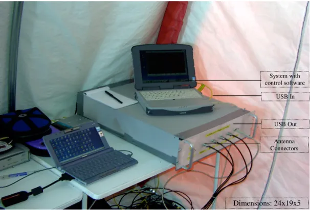
Remote Subsystem Local SubsystemThe remote subsystem system consistsof 4 Motorola-Iridium modems connected to a rugged laptop with an USB-to-Serial converter (figure 4.2 a).
(a) (b)
Figure 4.2 Four-channel Iridium communication unit and its antenna array
The antennas of these modems are installed on a metal plate of 1 sq ft that forms the ground plane. These four antennas are then mounted on a frame such that they are separated from each other by 2 ft in order to reduce the effects of interference (figure 4.2b). The PPP daemon (PPPD) on the remote terminal is configured as a PPP client so as to connect to the mainland terminal.The computer terminal at the mainland has four PSTN modems connected to it via a multi port serial card and an octopus cable. This terminal is configured as a PPP server to receive call from the remote Iridium system through 4 PSTN phone lines.
The developed link management software configures the remote terminal as a PPP client, dials the Iridium modem to establish the serial connection with the mainland
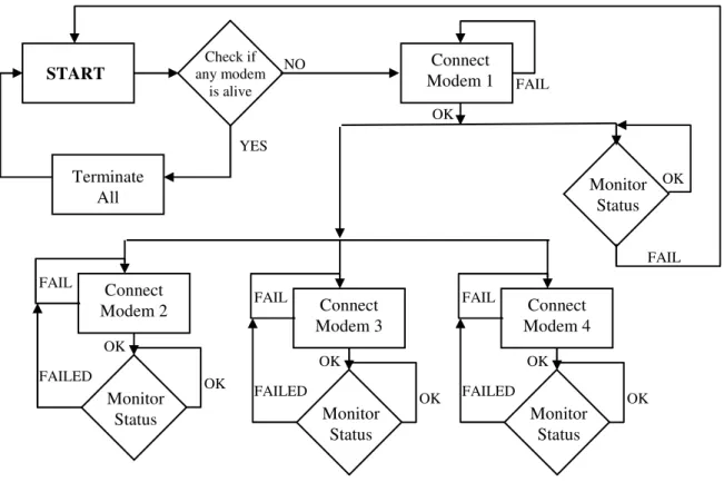
Once the basic connection is established, it dials the remaining modems and seamlessly attaches them to the first PPP connection, forming a single high bandwidth pipe. Standard Internet protocols, TCP/IP are then used to provide end-to-end connectivity. This MLPPP system developed in Linux also monitors the satellite connection, detects any call drops during satellite hand-offs and immediately reconnects dropped modems. Further, it handles power failures and system resets providing a reliable and fully autonomous data link. The following sections detail how each of the above functionalities is achieved.
4.2 Modem Control
As seen in figure 4.1, the remote unit uses Motorola-Iridium modems while the mainland facility uses regular PSTN modems. The PSTN modems are controlled using the MGETTY [25] software tool in Linux. Mgetty is configured such that it locks the serial lines to which the modems are connected, initializes the modems by running the init scripts from the configuration file and awaits the arrival of any incoming call. The modem is continuously monitored by Mgetty to ensure the readiness of the modem to receive an incoming call.
On the other hand, the Motorola-Iridium modems do not have Linux drivers. But, they do respond to modified Hayes AT command set. In order to communicate and control these modems, system scripts are written using the Linux CHAT facility. The CHAT scripts written with AT commands (as given in Appendix C) can be used to communicate with the modem to obtain its serial number, signal level
![Figure 1.1: Coverage map of Inmarsat (Source: [4])](https://thumb-us.123doks.com/thumbv2/123dok_us/8716178.2360003/15.918.248.728.693.929/figure-coverage-map-inmarsat-source.webp)
![Figure 1.2: Coverage map of Globalstar (Source: [5])](https://thumb-us.123doks.com/thumbv2/123dok_us/8716178.2360003/16.918.218.682.718.955/figure-coverage-map-globalstar-source.webp)
![Figure 2.4: Coverage area of a satellite (Source: [19])](https://thumb-us.123doks.com/thumbv2/123dok_us/8716178.2360003/28.918.293.650.678.990/figure-coverage-area-of-satellite-source.webp)
![Figure 2.6: The three panels of an Iridium phased array antenna (Source: [12])](https://thumb-us.123doks.com/thumbv2/123dok_us/8716178.2360003/30.918.238.710.288.678/figure-panels-iridium-phased-array-antenna-source.webp)
![Figure 2.14: PPP phase diagram (Source: [22])](https://thumb-us.123doks.com/thumbv2/123dok_us/8716178.2360003/44.918.169.820.228.464/figure-ppp-phase-diagram-source.webp)