Type 2 Tag Operation Specification
Technical Specification
T2TOP 1.1
NFC Forum
TMNFCForum-TS-Type-2-Tag_1.1
2011-05-31
license agreement entered into between the recipient (Licensee) and NFC Forum, Inc. (Licensor) and may be used only by Licensee, and in compliance with the terms of that license agreement (License). If you are not the Licensee, you may read this Specification, but are not authorized to implement or make any other use of this specification. However, you may obtain a copy of this Specification and implementation rights at the following page of Licensor's website: http://www.nfc-forum.org/specs/spec_license after entering into and agreeing to such license terms as Licensor is then requiring. On the date that this specification was downloaded by Licensee, the non-implementation terms of that license were as follows:
1. LICENSE GRANT.
Licensor hereby grants Licensee the right, without charge, to copy (for internal purposes only) and share this Specification with Licensee's members, employees and (to the extent related to Licensees use of this Specification) consultants. This license grant does not include the right to sublicense, modify or create derivative works based upon the Specification.
2. NO WARRANTIES.
THE SPECIFICATION IS PROVIDED "AS IS", WITHOUT WARRANTY OF ANY KIND, EXPRESS OR IMPLIED, INCLUDING BUT NOT LIMITED TO WARRANTIES OF MERCHANTABILITY, FITNESS FOR A PARTICULAR PURPOSE, ACCURACY, COMPLETENESS AND
NONINFRINGEMENT OF THIRD PARTY RIGHTS. IN NO EVENT SHALL LICENSOR, ITS MEMBERS OR ITS CONTRIBUTORS BE LIABLE FOR ANY CLAIM, OR ANY DIRECT, SPECIAL, INDIRECT OR CONSEQUENTIAL DAMAGES, OR ANY DAMAGES WHATSOEVER RESULTING FROM LOSS OF USE, DATA OR PROFITS, WHETHER IN AN ACTION OF CONTRACT,
NEGLIGENCE OR OTHER TORTIOUS ACTION, ARISING OUT OF OR IN CONNECTION WITH THE USE OR PERFORMANCE OF THE SPECIFICATION.
3. THIRD PARTY RIGHTS.
Without limiting the generality of Section 2 above, LICENSOR ASSUMES NO RESPONSIBILITY TO COMPILE, CONFIRM, UPDATE OR MAKE PUBLIC ANY THIRD PARTY ASSERTIONS OF PATENT OR OTHER INTELLECTUAL PROPERTY RIGHTS THAT MIGHT NOW OR IN THE FUTURE BE INFRINGED BY AN IMPLEMENTATION OF THE SPECIFICATION IN ITS CURRENT, OR IN ANY FUTURE FORM. IF ANY SUCH RIGHTS ARE DESCRIBED ON THE SPECIFICATION, LICENSOR TAKES NO POSITION AS TO THE VALIDITY OR INVALIDITY OF SUCH
ASSERTIONS, OR THAT ALL SUCH ASSERTIONS THAT HAVE OR MAY BE MADE ARE SO LISTED.
4. TERMINATION OF LICENSE.
In the event of a breach of this Agreement by Licensee or any of its employees or members, Licensor shall give Licensee written notice and an opportunity to cure. If the breach is not cured within thirty (30) days after written notice, or if the breach is of a nature that cannot be cured, then Licensor may immediately or thereafter terminate the licenses granted in this Agreement.
5. MISCELLANEOUS.
All notices required under this Agreement shall be in writing, and shall be deemed effective five days from deposit in the mails. Notices and correspondence to the NFC Forum address as it appears below. This Agreement shall be construed and interpreted under the internal laws of the United States and the Commonwealth of Massachusetts, without giving effect to its principles of conflict of law. NFC Forum, Inc.
401 Edgewater Place, Suite 600 Wakefield, MA, USA 01880
Contents
1
Introduction ... 1
1.1 Objectives ... 1
1.2 Applicable Documents or References ... 1
1.3 Administration ... 1
1.4 Name and Logo Usage ... 2
1.5 Intellectual Property ... 2
1.6 Special Word Usage ... 2
1.7 Convention and Notations ... 2
1.7.1 Representation of Numbers ... 2
1.8 Abbreviations ... 3
1.9 Glossary ... 3
2
Memory Structure and Management ... 4
2.1 Static Memory Structure ... 4
2.1.1 Internal Bytes ... 5
2.1.2 Static Lock bytes ... 5
2.1.3 Capability Container ... 5
2.1.4 Data Area for Static Memory Structure ... 6
2.2 Dynamic Memory Structure ... 6
2.2.1 Reserved Bytes ... 7
2.2.2 Static and Dynamic Lock Bits ... 7
2.2.3 Data Area for Dynamic Memory Structure ... 8
2.3 TLV blocks ... 9
2.3.1 NULL TLV ... 10
2.3.2 Lock Control TLV ... 10
2.3.3 Memory Control TLV ... 12
2.3.4 NDEF Message TLV ... 12
2.3.5 Proprietary TLV ... 13
2.3.6 Terminator TLV ... 13
3
RF Interface ... 14
4
Framing / Transmission Handling ... 15
5
Command Set ... 16
5.1 READ ... 16
5.2 WRITE ... 16
5.3 SECTOR SELECT ... 18
5.4 ACK and NACK ... 19
6
NDEF Detection and Access ... 20
6.1 NDEF Management ... 20
6.1.1 Version Treating ... 21
6.2 NDEF Storage ... 22
6.3 Life Cycle ... 22
6.3.1 INITIALIZED State ... 23
6.3.2 READ/WRITE State ... 23
6.3.3 READ-ONLY State ... 23
6.4 Command Sequence Description... 24
6.4.3 NDEF Write Procedure ... 25
6.4.4 State Changes ... 26
A.
Empty NDEF Message ... 28
B.
Memory Structure Examples ... 29
B.1 Example of Static Memory Structure ... 29
B.2 Example of Dynamic Memory Structure ... 30
C.
Examples of Command Flow ... 33
C.1 Static Memory Structure Examples ... 33
C.2 Detection of NDEF Message ... 33
C.2.1 Positive Detection of NDEF Message ... 33
C.2.2 Negative Detection of NDEF Message ... 34
C.3 Read of an NDEF message from the Data Area ... 35
C.4 Write of an NDEF message in the Data Area ... 35
C.5 Dynamic Memory Structure Examples ... 37
C.6 Detection of NDEF Message ... 37
C.7 Positive Detection of NDEF Message ... 37
C.8 Negative Detection of NDEF Message ... 38
C.9 Read of an NDEF message from the Data Area ... 39
C.10 Write of an NDEF message in the Data Area ... 39
D.
Type 2 Tag Platform State Machine ... 42
E.
Revision History ... 48
Figures
Figure 1: Static Memory Structure ... 5Figure 2: Example of Dynamic Memory Structure ... 6
Figure 3: Length Field Formats ... 9
Figure 4: Life Cycle with State Changes (transitions) ... 26
Figure 5: Example of Static Memory Structure... 29
Figure 6: Example of Dynamic Memory Structure ... 30
Figure 7: Type 2 Tag Platform State Machine ... 47
Tables
Table 1: Abbreviations ... 3Table 2: Defined TLV blocks ... 10
Table 3: READ ... 16
Table 4: WRITE ... 17
Table 5: SECTOR SELECT Command ... 18
Table 6: Example of coding of the CC bytes of block 3 ... 21
Table 8: Type 2 Tag Platform State Machine... 43 Table 9: Revision History ... 48
Requirements
Requirements 1: Listen Mode - ACTIVE_A and ACTIVE_A* Sub-states ... 45 Requirements 2: Listen Mode – CARD_EMULATOR_2 and CARD_EMULATOR_2* Sub-states 45 Requirements 3: Listen Mode – SECTOR_SELECT and SECTOR_SELECT* Sub-states ... 46
1 Introduction
This specification is part of the NFC Forum documentation about tag types that an NFC Forum Device needs to support in reader/writer mode.
This specification documents how an NFC Forum Device SHALL operate an NFC Forum Type 2 Tag Platform. This is not a specification of the NFC Forum Type 2 Tag Platform itself.
1.1 Objectives
The purpose of this specification is to document the requirements and to specify, with a set of rules and guidelines, the NFC Forum Device operation and management of the Type 2 Tag Platform.
This specification assumes that the Collision Detection and Device Activation activities have been performed as documented in [DIGITAL], [ACTIVITY], and [ANALOG].
This specification also defines the data mapping and how the NFC Forum Device detects, reads, and writes NDEF data into the Type 2 Tag Platform in order to achieve and maintain
interchangeability and interoperability.
1.2 Applicable Documents or References
[ACTIVITY] NFC Activity Specification, Version 1.0,
NFC Forum
[ANALOG] NFC Analog,
In progress, NFC Forum
[DIGITAL] NFC Digital Protocol, Version 1.0,
NFC Forum
[NDEF] NFC Data Exchange Format,
Version 1.0, NFC Forum
[RFC2119] Key words for use in RFCs to Indicate Requirement Levels, RFC 2119, S. Bradner,
March 1997,
Internet Engineering Task Force
1.3 Administration
The NFC Forum Type 2 Tag Operation Specification is an open specification supported by the Near Field Communication Forum, Inc., located at:
401 Edgewater Place, Suite 600 Wakefield, MA, 01880
Tel.: +1 781-876-8955 Fax: +1 781-610-9864
The NFC Devices Technical Working Group maintains this specification. Comments, errors, and other feedback can be submitted at
http://www.nfc-forum.org/apps/group_public/document.php?document_id=9775&wg_abbrev=chairs.
1.4 Name and Logo Usage
The Near Field Communication Forum’s policy regarding the use of the trademarks NFC Forum and the NFC Forum logo is as follows:
• Any company MAY claim compatibility with NFC Forum specifications, whether a member of the NFC Forum or not.
• Permission to use the NFC Forum logos is automatically granted to designated members only as stipulated on the most recent Membership Privileges document, during the period of time for which their membership dues are paid.
• Member’s distributors and sales representatives MAY use the NFC Forum logo in promoting member’s products sold under the name of the member.
• The logo SHALL be printed in black or in color as illustrated on the Logo Page that is available from the NFC Forum at the address above. The aspect ratio of the logo SHALL be maintained, but the size MAY be varied. Nothing MAY be added to or deleted from the logos.
• Since the NFC Forum name is a trademark of the Near Field Communication Forum, the following statement SHALL be included in all published literature and advertising material in which the name or logo appears:
NFC Forum and the NFC Forum logo are trademarks of the Near Field Communication Forum.
1.5 Intellectual Property
The Type 2 Tag Operation Specification conforms to the Intellectual Property guidelines specified in the NFC Forum's Intellectual Property Rights Policy, as outlined in the NFC Forum Rules of Procedure. These documents are available on the NFC Forum website.
1.6 Special Word Usage
The key words “MUST”, “MUST NOT”, “REQUIRED”, “SHALL”, “SHALL NOT”, “SHOULD”, “SHOULD NOT”, “RECOMMENDED”, “MAY”, and “OPTIONAL” in this document are to be interpreted as described in [RFC2119].
1.7 Convention and Notations
1.7.1 Representation of Numbers
The following conventions and notations apply in this document unless otherwise stated. • Binary numbers are represented by strings of digits 0 and 1 shown with the most significant
bit (msb) left and the least significant bit (lsb) right, “b” is added at the end. Example: 11110101b
• Hexadecimal numbers are represented using the numbers 0 - 9 and the characters A – F, an “h” is added at the end. The most significant byte (MSB) is shown on the left, the least significant byte (LSB) on the right.
Example: F5h
• Decimal numbers are represented as is (without any trailing character). Example: 245
1.8 Abbreviations
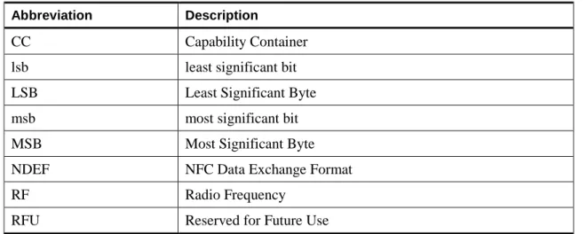
The abbreviations as used in this document are defined in Table 1. Table 1: Abbreviations Abbreviation Description
CC Capability Container
lsb least significant bit
LSB Least Significant Byte
msb most significant bit
MSB Most Significant Byte
NDEF NFC Data Exchange Format
RF Radio Frequency
RFU Reserved for Future Use
1.9 Glossary
Mandatory NDEF Message TLV, first NDEF Message TLV
NDEF Message TLV detected by the NDEF detection procedure NFC Forum Device
A device that supports the following modus operandi: Initiator, Target and Reader/Writer. It may also support Card Emulator.
NFC-Forum-Compliant Device
In this document, the NFC-Forum-Compliant device is always using the Reader/Writer modus operandi (for more information, see [DIGITAL]).
Type 2 Tag Platform
A legacy platform supporting a subset of a Technology (also called Technology Subset). Type 2 Tag Platform uses a particular subset of NFC – Type A technology including anticollision (for more information, see [DIGITAL]).
2 Memory Structure and Management
Type 2 Tag Platform is based on a particular memory chip with a certain memory size and space for data. The following sections describe the details of such memory chip and, in particular, its memory structure and management.
The memory structure (or layout) depends on the memory size of the tag:
• A static memory structure is used for tags with memory size equal to 64 bytes • A dynamic memory structure is used by tags with memory size bigger than 64 bytes The memory structure is divided in blocks containing 4 bytes each (see Figure 1 and Figure 2). Each block is numbered from 0 to 15 for static memory structure or from 0 to k for dynamic memory structure. The number associated with a block is also called “block number”. The 4 bytes inside each block are numbered from 0 to 3. For each block, byte 0 is the MSB and byte 3 is the LSB. Regarding the whole memory structure, Byte 0 of block 0 indicates the MSB, and the LSB is indicated either by Byte 3 of block 15 for static memory structure or byte 3 of block k for dynamic memory structure.
The blocks are grouped in sectors. A sector is defined as 256 contiguous blocks (1024 bytes or 1KB).
In this document, the bit and byte ordering when defining packets and messages follows the big-endian byte order.
The next two sections describe in details the two memory structures (also called “layouts”).
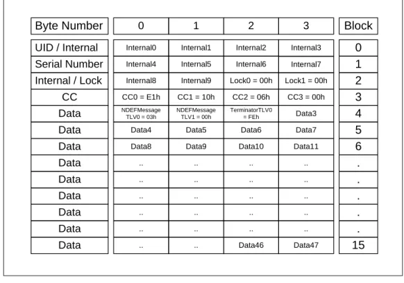
2.1 Static Memory Structure
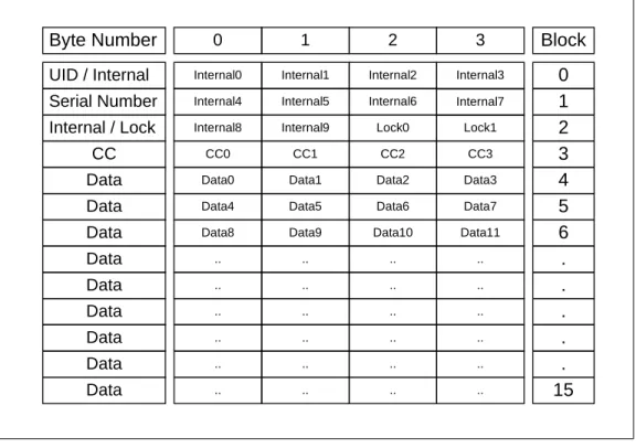
This memory structure is used by Type 2 Tag Platform with a physical memory size equal to 64 bytes. Figure 1 shows the memory layout of such tag. It is composed of different fields:
• Internal: Reserved bytes for manufacturing usage (see Section 2.1.1)
• Lock: Static lock bytes (see Section 2.1.2) to switch the tag from READ/WRITE state to READ-ONLY state (see Section 6.3)
• CC: Capability Container bytes (see Section 2.1.3) • Data: Bytes used to store information (see Section 2.1.4)
Byte Number 0 1 UID / Internal Internal0
2 3
Internal1 Internal2 Internal3
Serial Number Internal / Lock
CC
Internal4 Internal5 Internal6 Internal7
Internal8 Internal9 Lock0 Lock1
Data0 Data1 Data2 Data3
Data4 Data5 Data6 Data7
Data8 Data9 Data10 Data11
Block 0 1 2 3 4 5 Data Data Data Data Data Data Data Data .. .. .. .. .. .. .. .. .. .. .. .. .. .. .. .. .. .. .. .. .. .. .. ..
CC0 CC1 CC2 CC3
6 . . . . . 15 Data
Figure 1: Static Memory Structure
2.1.1 Internal Bytes
These bytes are reserved for manufacturing use.
[RQ_T2T_MEM_001] The NFC Forum Device SHALL NOT use internal bytes to store information data.
2.1.2 Static Lock bytes
The bits of byte 2 and 3 of block 2 represent the field-programmable read-only locking
mechanism called “static lock bytes”. Depending on the value of the bits of the static lock bytes, two configurations are possible:
• All bits are set to 0b, and the CC area and the data area of the tag can be read and written. • All bits are set to 1b, and the CC area and the data area of the tag can only be read. The locking bits are set to 1b via a standard write command to block 2 (BNo = 2). For more details, see Section 5.2.
[RQ_T2T_MEM_002] To set all static lock bits to 1b, the NFC Forum Device SHALL set Byte 3-4 of the WRITE command to FFh and set the remaining Byte 5-6 to any value.
This process is irreversible: if one bit of the lock bytes is set to 1b, it cannot be changed back to 0b.
2.1.3 Capability Container
The Capability Container (CC) manages the information of the Type 2 Tag Platform. The four bytes of block 3 contain the CC. See Section 6.1 for a detailed description of the CC.
2.1.4 Data Area for Static Memory Structure
Block 4 to 15 is the available data area for information storage.[RQ_T2T_MEM_003] The NFC Forum Device SHALL write the data area consecutively in order starting from byte 0 of block 4 up to byte 3 of block 15. For static memory structure, the data area size is equal to 48 bytes (see also the CC description in Section 6.1).
2.2 Dynamic Memory Structure
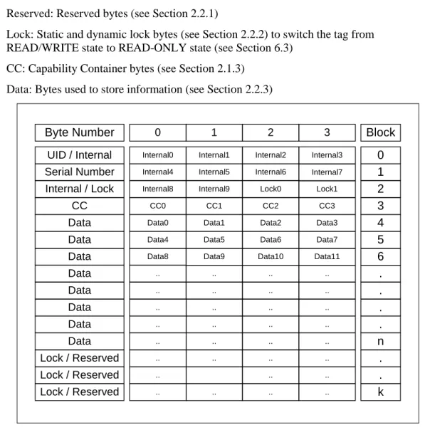
This memory structure (or layout) is applied to Type 2 Tag Platform with a memory size bigger than 64 bytes. Figure 2 shows an example of memory layout of such tag. It is composed of different fields:
• Internal: Bytes for manufacturing usage as defined in Section 2.1.1 • Reserved: Reserved bytes (see Section 2.2.1)
• Lock: Static and dynamic lock bytes (see Section 2.2.2) to switch the tag from READ/WRITE state to READ-ONLY state (see Section 6.3)
• CC: Capability Container bytes (see Section 2.1.3) • Data: Bytes used to store information (see Section 2.2.3)
1 0
Internal0
2 3
Internal1 Internal2 Internal3
Internal4 Internal5 Internal6 Internal7
Internal8 Internal9 Lock0 Lock1
Data0 Data1 Data2 Data3
Data4 Data5 Data6 Data7
Data8 Data9 Data10 Data11
Block 0 1 2 3 4 5 .. .. .. .. .. .. .. .. .. .. .. .. .. .. .. .. .. .. .. .. .. .. .. ..
CC0 CC1 CC2 CC3
6 . . . . n . .. .. .. .
.. .. .. .. k
Byte Number UID / Internal Serial Number Internal / Lock
CC Data Data Data Data Data Data Data Data Lock / Reserved Lock / Reserved Lock / Reserved
Figure 2: Example of Dynamic Memory Structure
In Figure 2, each block is numbered from 0 to k. The block n indicates the last block of the data area. Blocks from n+1 to k contain reserved or lock bytes.
NOTE Dynamic lock bytes and reserved bytes might be located at any byte address in between or at the end of the data areas starting from block 16. A more detailed example of dynamic memory structure is shown in Appendix B.
Compared to the static memory structure, the dynamic memory structure might contain optional configuration information to describe details of dynamic lock bits and to identify reserved memory areas in the data area using the Lock Control TLV and the Memory Control TLV (see Section 2.3).
2.2.1 Reserved Bytes
The reserved bytes belong to reserved memory areas.
[RQ_T2T_MEM_004] The NFC Forum Device SHALL ignore and jump over the reserved bytes during read and write operations. Reserved bytes are identified by one or more Memory Control TLV blocks (see Section 2.3.3).
2.2.2 Static and Dynamic Lock Bits
A tag with a dynamic memory structure contains two kinds of lock bits: • Static lock bits as specified in Section 2.1.2
• Dynamic lock bits described below in this section
The dynamic lock bits are called “dynamic” because their position(s) inside the tag can change. This is in contrast to the static lock bytes because their position is fixed (see Section 2.1.2). Lock areas are only needed on Type 2 Tag Platform that allows the transition from
READ/WRITE state to READ-ONLY state (see Section 6.4.4).
[RQ_T2T_MEM_005] The NFC Forum Device SHALL ignore and jump over the bytes that belong to lock areas during read operations of NFC Forum data inside Type 2 Tag Platform in READ-ONLY state (see Section 6.3).
The default settings of the dynamic lock bits are:
• The position of the dynamic lock bits starts from the first byte after the data area (see Section 2.2.3 and Figure 2). The bytes that contain the dynamic lock bits are called “dynamic lock bytes”.
• The number of dynamic lock bits is equal to data area size minus 48 (in bytes) divided by 8. If the division result is not an integer, the number of lock bytes is equal to the closest integer that is bigger than the division result. That is:
(
−
48
)
8
=
DataAreaSi
ze
its
namicLockB
NumberOfDy
The number of dynamic lock bytes is equal to:
(
−
48
)
64
=
DataAreaSi
ze
ytes
namicLockB
NumberOfDy
[RQ_T2T_MEM_006] When the number of the dynamic lock bits is not a multiple of 8, the last dynamic lock byte is partially filled with these bits. In this byte, the dynamic lock bits are located starting from the lsb to the msb. The part of the byte that does not contain dynamic lock bits is filled with reserved bits that the NFC Forum Device SHALL always set to 0b.
[RQ_T2T_MEM_007] The NFC Forum Device SHALL overrule the default settings of the dynamic lock bits when one or more Lock Control TLV blocks are present (see Section 2.3). The NFC Forum Device SHALL calculate the position and the number of the dynamic lock bits from the information contained in the Lock Control TLV.
Type 2 Tag Platforms that are delivered in READ-ONLY state can indicate the lock areas as reserved memory areas. This allows you to use one Memory Control TLV (see Section 2.3) to indicate contiguous and alternating lock areas, and reserved areas.
Depending on the values of the static and dynamic lock bits, two configurations are possible: • All bits are set to 0b, and the CC area and the data area of the tag can be read and written. • All bits are set to 1b, and the CC area and the data area of the tag can be only read. To set to 1b static lock bits, see Section 2.1.2.
[RQ_T2T_MEM_008] The NFC Forum Device SHALL set the dynamic locking bits to 1b via a standard WRITE command (see Section 5.2).
[RQ_T2T_MEM_009] Because the WRITE command is a block-wise command, the NFC Forum Device SHALL set to 1b only the bits that belong to the dynamic lock bits of the block. If a block contains one or more dynamic lock bytes and one or more non-lock bytes, the NFC Forum Device MAY first send a READ command (see Section 5.1) and then a WRITE command on the same block. From the response of the READ command, the values of the non-lock bytes are retrieved. The NFC Forum Device MAY use these values in the WRITE command to avoid changing the value of the non-lock bytes and to set the dynamic lock bits to 1b.
The setting of the static and dynamic lock bits is irreversible: if one bit lock bit is set to 1b, it cannot be changed back to 0b.
2.2.3 Data Area for Dynamic Memory Structure
[RQ_T2T_MEM_010, RQ_T2T_MEM_011] The data area for dynamic memory structure is contained from block 4 up to the last block of the memory, including the 48 bytes of the static memory structure (see Section 2.1) and excluding dynamic lock bytes and reserved bytes. The data area is the only memory area where the NFC Forum Device SHALL read and write the TLV blocks (see Section 2.3).
[RQ_T2T_MEM_012] The NFC Forum Device SHALL write the data area sequentially starting from byte 0 of block 4 to byte 3 of block k, jumping over dynamic lock bytes and reserved bytes. The data area size in bytes is equal to: 4⋅(k−3)−DynamicLockBytes−ReservedBytes The previous calculation includes the data area of the static memory structure equal to 48 bytes (see Section 2.1) and supposes that the first block is numbered starting from 0 (i.e., block 0). The value k indicates the overall number of blocks that belong to one or more sectors is reduced by 1. E.g., a dynamic memory structure composed of 2 sectors has 512 blocks; hence, k is equal to 511. For dynamic memory structure, k is bigger than 15 (i.e., k>15).
Compared to the static memory structure, the dynamic memory structure adds a number of data area bytes equal to: 4⋅(k−3)−DynamicLockBytes−ReservedBytes−48
The memory starting from block 16 contains all dynamic lock bytes, all reserved bytes (see also NOTE on page 7), and all data area bytes added by the dynamic memory structure.
2.3 TLV blocks
A TLV block consists of one to three fields:
• [RQ_T2T_MEM_013] T (tag field or T field) identifies the type of the TLV block (see Table 2) and consists of a single byte encoding a number from 00h to FFh. The tag values 04h to FCh and FFh are reserved for future use by the NFC Forum.
• [RQ_T2T_MEM_014, RQ_T2T_MEM_015] L (length field or L field) provides the size in bytes of the value field. It has two different formats composed of one or three bytes. The NFC Forum Device SHALL understand both length field structures. Figure 3 shows the two different length field structures. However, depending on the tag field value, the length field may not be present.
• One byte format: The NFC Forum Device SHALL use the one byte format to code the
length of the value field between 00h and FEh bytes. The NFC Forum Device SHALL interpret this byte as a cardinal if the value is between 00h and FEh. If it contains FFh, the NFC Forum Device SHALL interpret the value as flag that specifies that the length field is composed of more than one byte.
• Three consecutive bytes format: The NFC Forum Device SHALL use this format to
code the length of the value field between 00FFh and FFFEh bytes. The first byte is assumed to be a flag equal to FFh indicating that two more bytes are present. The NFC Forum Device SHALL interpret those two bytes as a word. The NFC Forum Device SHALL interpret this word as a cardinal if the value is between 00FFh and FFFEh. The value FFFFh is reserved for future use (RFU).
00h-FEh
00FFh-FFFEh FFh
1 byte format
3 bytes format Figure 3: Length Field Formats
• [RQ_T2T_MEM_016, RQ_T2T_MEM_017] V (value field or V field) indicates the value field. If the length field is equal to 00h or there is no length field, the value field is not present (i.e., the TLV block is empty). If the length field is there and it indicates a length of N bigger than zero (N>0), the value field consists of N consecutive bytes.
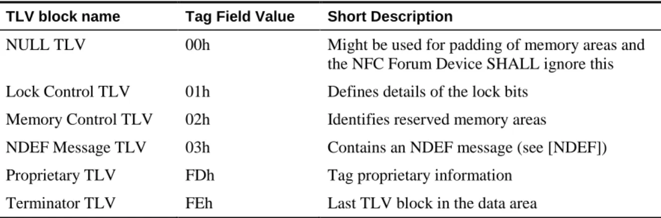
Table 2 lists the TLV blocks specified by this document that are described in the following sections.
Table 2: Defined TLV blocks TLV block name Tag Field Value Short Description
NULL TLV 00h Might be used for padding of memory areas and
the NFC Forum Device SHALL ignore this Lock Control TLV 01h Defines details of the lock bits
Memory Control TLV 02h Identifies reserved memory areas
NDEF Message TLV 03h Contains an NDEF message (see [NDEF]) Proprietary TLV FDh Tag proprietary information
Terminator TLV FEh Last TLV block in the data area
[RQ_T2T_MEM_018, RQ_T2T_MEM_019] The NFC Forum Device SHALL write the TLV blocks in a specific order inside the data area (see Section 2.1.4 and Section 2.2.3) following the rules below:
• NDEF Message TLVs and Proprietary TLVs are present after all Lock Control TLVs and Memory Control TLVs.
• If present, the Terminator TLV is the last TLV block on the Type 2 Tag Platform.
NULL TLV and Terminator TLV are the only TLV blocks that are 1 byte long (i.e., composed of only the Tag field, see Section 2.3.1 and Section 2.3.2).
[RQ_T2T_MEM_020] NFC Forum Devices SHALL ignore and jump over those TLV blocks that make use of reserved tag field values. To jump over a TLV block with reserved tag field values, the NFC Forum Device SHALL read the length field to understand the length of the value field.
NOTE Future definitions of TLV blocks composed of only the tag field are not backward compatible with this NFC Forum specification.
2.3.1 NULL TLV
[RQ_T2T_MEM_032] The Null TLV can be used for padding of the data area. A Type 2 Tag Platform contains zero, one, or more NULL TLVs. The NFC Forum Device SHALL ignore and jump over this TLV block. NULL TLV is composed of a 1 byte tag field. The encoding of the tag field of the NULL TLV is:
• T is equal to 00h (see Table 2). • L is not present.
• V is not present.
2.3.2 Lock Control TLV
[RQ_T2T_MEM_021] The Lock Control TLV can be present inside the Type 2 Tag Platform. An NFC Forum Device SHALL be able to read and process it.
The Lock Control TLV provides control information about the lock areas where the dynamic lock bytes are located (see Section 2.2.2). Each Lock Control TLV indicates a single lock area. More lock areas are indicated using more Lock Control TLV blocks.
[RQ_T2T_MEM_022] Below the encoding of the 3 TLV fields of the Lock Control TLV are shown:
• T is equal to 01h (see Table 2). • L is equal to 03h.
• V is composed of 3 bytes that uniquely identify the position and the size of the lock area, and the number of bytes locked by each bit of the dynamic lock bytes. The 3 bytes are encoded: • Position, MSB. Codes the position inside the tag of the lock area. The position byte
consists of 2 parts (to calculate the bytes address from the position byte, see the formula later in this section.
• PagesAddr. Most significant nibble (4 bits), coded as number of pages (0h=0…Fh=15)
• ByteOffset. Least significant nibble, coded as number of bytes (0h=0…Fh=15) • Size. Middle byte, coded as number of bits (01h=1…FFh=255, 00h=256). It indicates the
size in bits of the lock area (i.e., the number of dynamic lock bits). If the number of dynamic lock bits is not a multiple of 8, they are stored inside the dynamic lock bytes as explained in the description of the default setting of the dynamic lock bits (see
Section 2.2.2).
• Page control, LSB. Provides general control information: the size in bytes of a page and the number of bytes that each dynamic lock bit is able to lock. Page control byte is split up into two nibbles of 4 bits each:
[RQ_T2T_MEM_024] BytesPerPage: Least significant nibble, coded as 2n (0h=RFU, 1h=1…Fh=15). It indicates the number of bytes per page.
[RQ_T2T_MEM_025] BytesLockedPerLockBit: Most significant nibble, coded as 2n (0h=RFU, 1h=1…Fh=15). It indicates the number of bytes that each dynamic lock bit is able to lock. [RQ_T2T_MEM_023] The NFC Forum Device SHALL calculate the byte address (ByteAddr) of the beginning of the lock area as follows:
ByteOffset
PageAddr
ByteAddr
=
⋅
2
BytesPerPage+
ByteAddr is calculated from the beginning of the overall memory tag; Byte 0 of Block 0 is indicated by ByteAddr equal to 0.
ByteAddr is used to read and write the relative lock area using the appropriate READ and WRITE commands (see Section 5). The page definition has nothing to do with the block definition used by READ and WRITE commands.
An example of use of the BytesLockedPerLockBit is if the memory area locked by a single dynamic lock bit is 8 bytes, the BytesLockedPerLockBit is equal to 3 (i.e., 2BytesLockedPerLockBit=23=8 bytes).
NOTE The Lock Control TLV might be skipped if a Type 2 Tag Platform is in READ-ONLY state (see Section 6.3). Lock Control TLV blocks can be replaced by Memory Control TLV, indicating the same memory areas for Type 2 Tag Platform in READ-ONLY state (see Section 2.3.3).
2.3.3 Memory Control TLV
[RQ_T2T_MEM_026] The Memory Control TLV can be present inside the Type 2 Tag Platform and an NFC Forum Device SHALL be able to read and process it. It provides control information about the reserved areas where the reserved bytes are located (see Section 2.2.1) and the size of the reserved bytes.
If the Type 2 Tag Platform is delivered by the vendors in READ-ONLY state (see Section 6.3), the NFC Forum Device MAY use the Memory Control TLV to indicate control information for reserved and lock areas. Contiguous and alternating lock and reserved areas MAY be indicated by a single Memory Control TLV.
[RQ_T2T_MEM_027] The encoding of the 3 TLV fields of Memory Control TLV is: • T is equal to 02h (see Table 2).
• L is equal to 03h.
• V uniquely identifies the position and the size of the reserved area and is composed of three votes. The 3 bytes are encoded:
• Position, MSB. It codes the position inside the tag of the reserved area. The Position byte consists of 2 parts (to calculate the bytes address from the position byte, see the formula below):
• PagesAddr. Most significant nibble, coded as number of pages (0h=0…Fh=15) • ByteOffset. Least significant nibble, coded as number of bytes (0h=0…Fh=15) • Size. Middle byte, coded as number of bytes (1h=1, FFh=255, 0h=256). It indicates the
size in bytes of the reserved area.
• Partial Page Control, LSB. Provides the size in bytes of a page. It is split up into two nibbles of 4 bits each:
• [RQ_T2T_MEM_029] BytesPerPage nibble: Least significant nibble, coded as 2n (0h=RFU, 1h=1…Fh=15). It indicates the number of bytes per page.
• Most significant nibble is RFU.
[RQ_T2T_MEM_028] The NFC Forum Device SHALL calculate the byte address (ByteAddr) of each reserved area as follows:
ByteOffset
PageAddr
ByteAddr
=
⋅
2
BytesPerPage+
The ByteAddr is calculated from the beginning of the overall memory tag; Byte 0 of Block 0 is indicated by ByteAddr equal to 0.
The page definition has nothing to do with the block definition used by READ and WRITE commands (see Section 5).
2.3.4 NDEF Message TLV
NDEF Message TLV is always present inside the Type 2 Tag Platform. It stores the NDEF message inside the Value field (see [NDEF]).
[RQ_T2T_MEM_030] The NFC Forum Device SHALL be able to read and process the first (or mandatory) NDEF message (see Section 6.4.1); further NDEF Message TLV blocks can be present. The mandatory and always present NDEF Message TLV provides the starting point when writing the NDEF Message into the Type 2 Tag. That is, an NDEF Message cannot be written before the NDEF Message TLV, which avoids corrupting the possible Memory and Lock Control TLVs (see Section 6.4.3).
[RQ_T2T_MEM_031] The encoding of the 3 TLV fields of NDEF Message TLV is: • T is equal to 03h (see Table 2).
• L is equal to the size in bytes of the stored NDEF message. • V stores the NDEF message (see [NDEF]).
An empty NDEF Message TLV is defined as an NDEF Message TLV with L field equal to 00h and no V field (i.e., no NDEF message is present in the V field). See [NDEF]).
A non-empty NDEF Message TLV can contain either empty or non-empty NDEF messages. See Appendix A for the definition of empty NDEF message.
2.3.5 Proprietary TLV
The Proprietary TLV contains proprietary information. A Type 2 Tag Platform contains zero, one, or more Proprietary TLVs. The NFC Forum Device MAY ignore the data contained in this TLV block. The encoding of the 3 TLV fields of Proprietary TLV is:
• T is equal to FDh (see Table 2).
• L is equal to the size in bytes of the proprietary data in the Value field. • V contains any proprietary data.
2.3.6 Terminator TLV
[RQ_T2T_MEM_033] The Terminator TLV can be present inside the Type 2 Tag Platform, and an NFC Forum Device SHALL be able to read and process it. The Terminator TLV is the last TLV block in the data area. Terminator TLV is composed of a 1 byte tag field. The encoding of the tag fields of the Terminator TLV is:
• T is equal to FEh (see Table 2). • L is not present.
3 RF Interface
The RF interface of the NFC Forum Device is defined in [ANALOG].
[RQ_T2T_RFI_001] The NFC Forum Device SHALL comply with the RF interface as defined in the relevant clauses of [ANALOG].
4 Framing / Transmission Handling
This section describes the framing (also called packet structures) and the transmission handling of the NFC Forum Device.
[RQ_T2T_FTH_001] The NFC Forum Device SHALL comply with the sequence format, the bit level coding, the frame format, the data and payload format, and the command set related to the Type 2 Tag Platform as defined in [DIGITAL], including the activation sequence of the Type 2 Tag Platform as defined in [ACTIVITY].
5 Command Set
This section describes the command set of the NFC Forum Device. The Command Set is described in Section 9.5 of [DIGITAL].
5.1 READ
[RQ_T2T_CSE_001] The NFC Forum Device SHALL comply with the READ Command described in Section 9.6 of [DIGITAL].
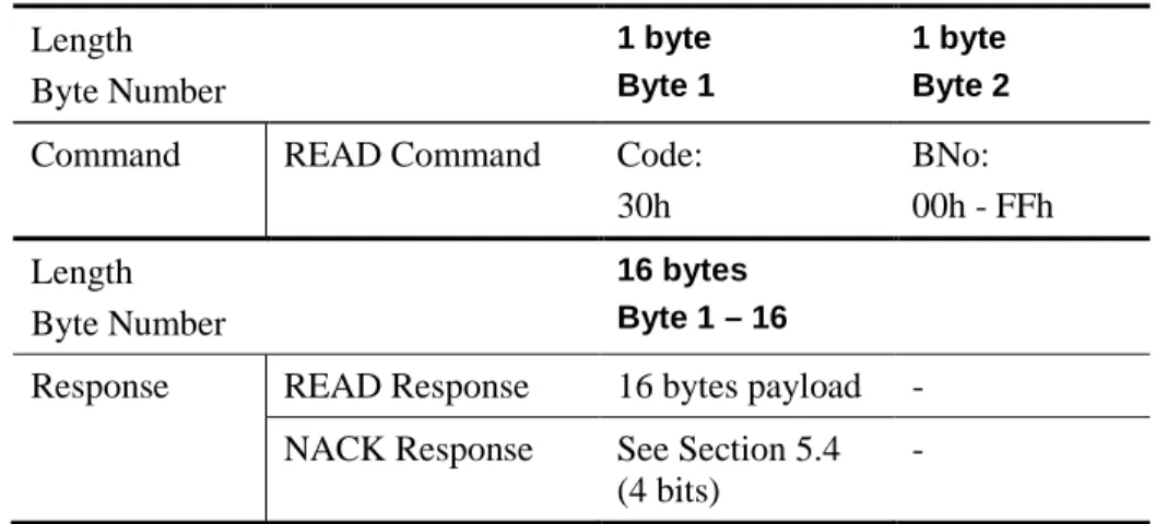
Table 3 describes the READ commands and the relative responses. Table 3: READ
Length Byte Number
1 byte Byte 1
1 byte Byte 2
Command READ Command Code:
30h
BNo: 00h - FFh Length
Byte Number
16 bytes Byte 1 – 16
Response READ Response 16 bytes payload - NACK Response See Section 5.4
(4 bits)
-
The READ command has command code 30h and needs the block number (BNo) as a parameter. The block number is explained in Section 2. The Type 2 Tag Platform responds to a READ command by sending 16 bytes, starting from the block number defined in the READ command (e.g., if BNo is equal to 03h, then blocks 3, 4, 5, and 6 are returned). The memory organization of the Type 2 Tag Platform is described in Section 2. In case of error, the Type 2 Tag Platform sends a NACK response.
[RQ_T2T_CSE_002] The READ command is unable to select the sector (see Section 2.2). The READ command reads blocks that belong to the currently selected sector. To select a different sector, the SECTOR SELECT command is used. To calculate the block number (BNo) from the byte address (ByteAddr, see Section 2.3.1 and Section 2.3.3), the NFC Forum Device SHALL use the expression
BNo
=
ByteAddr
4
. If the formula gives as a result BNo bigger than 255, the block indicated by BNo does not belong to sector 0 (default sector). In this case, the NFC Forum Device SHALL use the SECTOR SELECT command first to switch to the correct sector (SecNo) equal toSecNo
=
BNo
256
. Then the NFC Forum Device SHALL use the READ command with the adapted block number (BNo’) instead of BNo. The NFC Forum Device SHALLcalculate BNo’ from the formula
BNo
'
=
BNo
mod
256
. With Mod, the module operation gives the remainder of the divisionByteAddr
256
.5.2 WRITE
[RQ_T2T_CSE_004] The NFC Forum Device SHALL comply with the WRITE Command described in Section 9.7 of [DIGITAL].
Table 4 describes the WRITE commands and the relative responses ACK Response and NACK Response.
Table 4: WRITE
Length Byte Number
1 byte Byte 1
1 byte Byte 2
4 bytes Byte 3 – 6 Command WRITE Command Code:
A2h
BNo: 00h – FFh
Data
Length Byte Number
4 bits -
Response ACK Response See Section 5.4 - -
NACK Response See Section 5.4 - -
The WRITE command has the command code A2h followed by the block number (BNo) parameter.
[RQ_T2T_CSE_005] The NFC Forum Device SHALL use the WRITE command for
programming data. This MAY be the CC bytes (see Section 6.1), the lock bytes, or the data area bytes (see Section 2).
[RQ_T2T_CSE_006] The NFC Forum Device SHALL use the WRITE command block-wise, programming 4 bytes at once.
If the WRITE command is executed successfully by the Type 2 Tag Platform, the ACK response is sent back. In case of error, the Type 2 Tag Platform sends a NACK response.
[RQ_T2T_CSE_007] The WRITE operation is block-wise (i.e., it always writes the 4 bytes of the whole block). The NFC Forum Device SHALL write the new byte values and overwrite with the same values the bytes that remain unchanged. The NFC Forum Device MAY read the block first (i.e., READ operation), if the values of the bytes that remain unchanged are not known in advance.
The WRITE command is unable to select the sector (see Section 2.2). The WRITE command reads blocks that belong to the currently selected sector. To select a different sector, the SECTOR SELECT command is used.
[RQ_T2T_CSE_008] To calculate the block number (BNo) from the byte address (ByteAddr, see Section 2.3.1 and Section 2.3.3) the NFC Forum Device SHALL use the following expression
ByteAddr
4
BNo
=
. If the formula gives as a result BNo bigger than 255, the block indicated by BNo does not belong to sector 0 (default sector). In this case, the NFC Forum Device SHALL use the SECTOR SELECT command first to switch to the correct sector (SecNo) equal to
BNo
256
SecNo
=
. Then the NFC Forum Device SHALL use the WRITE command with theadapted block number (BNo’) instead of BNo. To calculate BNo’, the NFC Forum Device SHALL use the formula
BNo
'
=
BNo
mod
256
. With Mod, the module operation gives the remainder of the divisionByteAddr
256
.5.3 SECTOR SELECT
The NFC Forum Device SHALL comply with the SECTOR SELECT Command described in Section 9.7 of [DIGITAL].
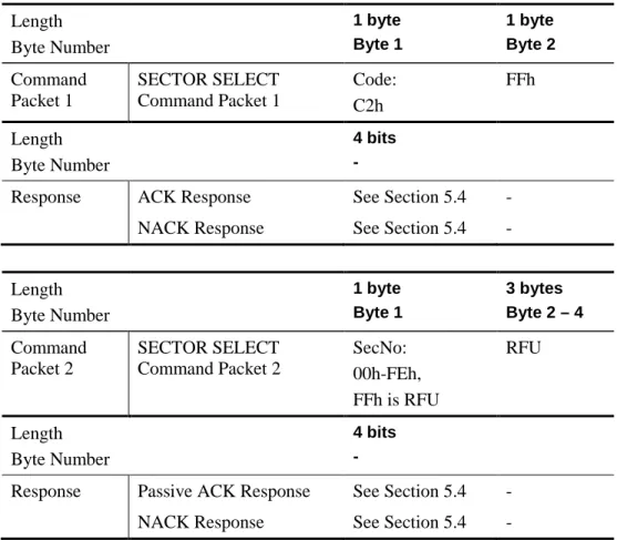
Table 5 describes the SECTOR SELECT command divided into 2 command packets and the relative responses ACK Response, passive ACK Response, and NACK Response.
Table 5: SECTOR SELECT Command
Length Byte Number 1 byte Byte 1 1 byte Byte 2 Command Packet 1 SECTOR SELECT Command Packet 1
Code: C2h FFh Length Byte Number 4 bits -
Response ACK Response See Section 5.4 -
NACK Response See Section 5.4 -
Length Byte Number
1 byte Byte 1
3 bytes Byte 2 – 4 Command
Packet 2
SECTOR SELECT Command Packet 2
SecNo: 00h-FEh, FFh is RFU
RFU
Length Byte Number
4 bits -
Response Passive ACK Response See Section 5.4 - NACK Response See Section 5.4 -
[RQ_T2T_CSE_013] The NFC Forum Device SHALL use the SECTOR SELECT command to address physical memory bigger than 1 KB (>1024 bytes).
Using SECTOR SELECT, it is possible to select a specific memory sector. The size of each sector is 1Kbyte.
The SECTOR SELECT command is divided into two packets called Command Packet 1 and Command Packet 2.
[RQ_T2T_CSE_015] The Command Packet 1 contains the 1 byte command code (equal to C2h), the 1 byte parameter (equal to FFh), and the 2 bytes CRC. The NFC Forum Device SHALL send the SECTOR SELECT Command Packet 1 first. A Type 2 Tag Platform with memory smaller than 1KB answers with a NACK Response to a SECTOR SELECT Command Packet 1. Type 2 Tag Platform with memory bigger than 1KB answers with an ACK to a SECTOR
SELECT Command Packet 1. After receiving an ACK, the NFC Forum Device SHALL send the SECTOR SELECT Command Packet 2. This is four bytes with CRC and parity packet.
[RQ_T2T_CSE_017] The first byte in the SECTOR SELECT Command Packet 2 is the chosen sector number (SecNo). The following 3 bytes are reserved for future use and set to 00h. If the sector number is inside the addressable data memory, no further packet is sent (passive ACK Response), and the sector is selected accordingly by the Type 2 Tag Platform. A NACK
Response is sent by the Type 2 Tag Platform, if the addressable data memory space is exceeded. The chosen sector stays valid until a protocol infringement occurs or a new sector is addressed. The default sector after power up (and after a protocol infringement) is 00h (called sector 0). [RQ_T2T_CSE_018] The SECTOR SELECT command can select up to 254 different sectors: the SecNo range is from 00h to FEh and the value FFh MUST be reserved for future use (RFU).
5.4 ACK and NACK
The NFC Forum Device SHALL comply with the ACK Response, Passive ACK Response, and NACK Response described in Section 9 of [DIGITAL].
6 NDEF Detection and Access
This section describes how the NFC Forum Device stores and accesses the NFC Forum data in the Type 2 Tag Platform.
6.1 NDEF Management
The NFC Forum Device reads the Capability Container (CC) to detect and access the NFC Forum defined data inside the Type 2 Tag Platform. The CC contains NFC Forum management data. The CC is stored in the block 3 of the static or dynamic memory structure (see Section 2). The CC bytes can be written using the WRITE command (see Section 5.2). The 4 data bytes of the WRITE command and the current contents of the 4 CC bytes are bit-wise “OR-ed” and the result is the new contents of the CC bytes. This process is irreversible. If a bit is set to 1b, it cannot be changed back to 0b again.
[RQ_T2T_NDA_001] The NFC Forum Device SHALL NOT use the CC to store any application related data.
[RQ_T2T_NDA_002, RQ_T2T_NDA_003] The NFC Forum Device SHALL code the CC bytes of block 3 as follows:
1. Byte 0 is equal to E1h (magic number) to indicate that NFC Forum defined data is stored in the data area (see Section 2).
2. Byte 1 is the version number of this document supported by the Type 2 Tag Platform (see Section 6.1.1). The most significant nibble (i.e., the 4 most significant bits) indicates the major version number and the least significant nibble (the 4 least significant bits) indicates the minor version number. The version number of this specification has major version
number equal to 1h and minor version number equal to 0h (i.e., the version is v1.0 and Byte 1 is equal to 10h).
3. Byte 2 indicates the memory size of the data area of the Type 2 Tag Platform. The value of byte 2 multiplied by 8 is equal to the data area size measured in bytes. For example: • 48 bytes are indicated by byte 2 value equal to 06h
• 128 bytes are indicated by byte 2 value equal to 10h • 2040 bytes are indicated by byte 2 value equal to FFh
4. Byte 3 indicates the read and write access capability of the data area and CC area of the Type 2 Tag Platform.
• The most significant nibble (the 4 most significant bits) indicates the read access condition:
• The value 0h indicates read access granted without any security. • The values from 1h to 7h and Fh are reserved for future use. • The values from 8h to Eh are proprietary.
• The least significant nibble (the 4 least significant bits) indicates the write access condition:
• The value 0h indicates write access granted without any security. • The values from 1h to 7h are reserved for future use.
• The values from 8h to Eh are proprietary.
• The value Fh indicates no write access granted at all.
Table 6 shows an example of coding of the CC bytes. The example is related to a Type 2 Tag Platform:
• With NFC Forum defined data (byte 0 = E1h)
• Supporting version 1.0 (major number 1h, minor number 0h) of the mapping document (byte 1 = 10h)
• With 128 bytes of the data area size (byte 2 = 10h)
• With read and write access granted without any security (byte 3 = 00h) Table 6: Example of coding of the CC bytes of block 3
Byte 0 Byte 1 Byte 2 Byte 3
E1h 10h 10h 00h
6.1.1 Version Treating
The Byte 1 of the CC contains the version of the applied mapping document to the Type 2 Tag Platform. The mapping document version is indicated with two numbers: major number version and minor version number.
[RQ_T2T_NDA_004] The handling of the different mapping document version numbers applied to the Type 2 Tag Platform (called T2VNo) and the one implemented in the NFC Forum Device (called NFCDevVNo) is explained in the four cases of Table 7.
Table 7: Handling of the mapping document version numbers No Version Number Case Handling
1 Major NFCDevVNo is equal to major T2VNo, and
minor NFCDevVNo is bigger than or equal to minor T2VNo
The NFC Forum Device SHALL access the Type 2 Tag Platform and SHALL use all features of the applied mapping document to this Type 2 Tag Platform.
2 If major NFCDevVNo is equal to major T2VNo, and minor NFCDevVNo is lower than minor T2VNo
Possibly not all features of the Type 2 Tag Platform can be accessed. The NFC Forum Device SHALL use all its features and SHALL access this Type 2 Tag Platform.
3 If major NFCDevVNo is smaller than major T2VNo
Incompatible data format. The NFC Forum Device cannot understand the Type 2 Tag Platform data. The NFC Forum Device SHALL reject this Type 2 Tag Platform.
4 If major NFCDevVNo is bigger than major T2VNo
The NFC Forum Device might implement the support for previous versions of this specification in addition to its main version. In case the NFC Forum Device has the support from previous version, it SHALL access the Type 2 Tag Platform. On the contrary, in case the NFC Forum Device has not the support from previous version, it SHALL reject the Type 2 Tag Platform.
NOTE Future versions of this specification have to define the allowed actions to an NFC Forum Tag with a version number lower than the version number of the NFC Forum Device (e.g., whether it is allowed to upgrade the tag to the new version).
6.2 NDEF Storage
The data format of the NDEF message is defined in [NDEF]. The NDEF message is stored inside the value field of the NDEF Message TLV (see Section 2.3.4) in the data area of the Type 2 Tag Platform (see Section 2). In the following section, the NDEF Message TLV is always the NDEF Message TLV detected by the NDEF detection procedure (see Section 6.4.1).
6.3 Life Cycle
An NFC Forum Device MAY detect a Type 2 Tag Platform in different states. The state is reflected by the content of the Type 2 Tag Platform. Every state has its own valid operations. The state transitions are only relevant for NFC Forum Devices, which are capable of writing Type 2 Tag Platform.
[RQ_T2T_NDA_005] The Type 2 Tag Platform can be in one of the following states: INITIALIZED, READ/WRITE, or READ-ONLY.
[RQ_T2T_NDA_006] If the Type 2 Tag Platform is not in a valid state according to the
specification of the NFC Forum, the NFC Forum Device SHALL ignore the Type 2 Tag Platform and its data.
The reasons might be: • Misconfigured CC area
• Not allowed NDEF Read Procedure (see Section 6.4.2), if Type 2 tag is in READ/WRITE or READ-ONLY state
• Not allowed NDEF Write Procedure (see Section 6.4.3), if Type 2 tag is in INITIALIZED or READ/WRITE state
• Mismatch between overall TLV blocks length and actual length of the data area • Invalid TLV block
6.3.1 INITIALIZED State
In this state the NFC Forum Device MAY modify the content of the NFC Forum defined data (i.e., NDEF Message TLV in the Type 2 Tag Platform).
[RQ_T2T_NDA_007] The NFC Forum Device SHALL detect a Type 2 Tag Platform in INITIALIZED state when all of the following are true:
• The CC area is set as described in Section 6.1 with byte 3 equal to 00h (read/write access granted)
• The data area contains an NDEF Message TLV
• The length field of NDEF Message TLV is equal to 00h
6.3.2 READ/WRITE State
In this state, the NFC Forum Device MAY modify the content of the NFC Forum defined data (i.e., NDEF Message TLV in the Type 2 Tag Platform).
[RQ_T2T_NDA_008] The NFC Forum Device SHALL detect a Type 2 Tag Platform in READ/WRITE state when all of the following are true:
• The CC area is set as described in Section 6.1 with byte 3 equal to 00h (read/write access granted)
• The data area contains an NDEF Message TLV
• The length field of NDEF Message TLV is different from zero and equal to the actual length of the NDEF message in the value field
6.3.3 READ-ONLY State
In this state, the CC and the whole data area are set to read-only.
[RQ_T2T_NDA_009] The NFC Forum Device SHALL detect a Type 2 Tag Platform in READ-ONLY state when all of the following are true:
• The CC area is set as described in Section 6.1 with byte 3 equal to 0Fh (only read access granted)
• The data area contains an NDEF Message TLV
• The length field of NDEF Message TLV SHALL be different from zero and equal to the actual length of the NDEF message in the value field
6.4 Command Sequence Description
In this section, several procedures are described to manage NFC Forum defined data (e.g., NDEF Message TLV that contains an NDEF message). The different state changes or transitions
between the states of the Type 2 Tag Platform are shown in detail.
6.4.1 NDEF Detection Procedure
[RQ_T2T_NDA_010] The NFC Forum Device SHALL use the NDEF detection procedure to detect the presence of an NDEF message (see [NDEF]) inside a Type 2 Tag Platform.
The NDEF Message TLV that is found by the NDEF detection procedure is also called “mandatory NDEF Message TLV” or “first NDEF Message TLV”.
The detection procedure is based on the control of byte 0 and 1 of the CC, and the presence of an NDEF Message TLV that MAY contain an NDEF message.
[RQ_T2T_NDA_011] The NDEF detection procedure is:
1. Read the CC (block 3) using the READ command specified in Section 5.1.
2. If byte 0 is equal to E1h, byte 1 describes the right version number (see Section 6.1.1), and the most significant nibble of byte 3 in block 3 is equal to 0h, then go to item 3. Otherwise, no NDEF data is detected in the Type 2 Tag Platform.
3. Read the data area sequentially using the READ command specified in Section 5.1, starting from block 4 and search for NDEF Message TLV. Stop the searching as soon as a first NDEF Message TLV is found. If no NDEF message TLV is detected in the Type 2 Tag Platform, the tag is not in a valid state.
4. If NDEF Message TLV is found:
• If the length field is different from zero, the NDEF message (see [NDEF]) is detected in the Type 2 Tag Platform.
• If the length field is equal to zero, no NDEF Message is detected. The tag might be in an INITIALIZED state.
[RQ_T2T_NDA_013] If the data to be read exceeds one or more sectors, the NFC Forum Device SHALL use the SECTOR SELECT command (see Section 5.3).
[RQ_T2T_NDA_012] During the NDEF detection procedure, the NFC Forum Device SHALL ignore and jump over reserved memory areas or dynamic lock bit areas indicated by Memory Control TLVs or Lock Control TLVs.
NOTE The NDEF detection procedure does not relate to a valid NDEF message (see [NDEF]). It reads the length of the store NDEF data and does not parse the NDEF data itself.
6.4.2 NDEF Read Procedure
The NDEF read procedure makes use of the READ command.
[RQ_T2T_NDA_014] The NFC Forum Device SHALL use the NDEF read procedure to read the NDEF message after having detected the NDEF message using the NDEF detection procedure (see Section 6.4.1).
[RQ_T2T_NDA_015] If the NDEF detection procedure does not detect the presence of the NDEF message inside the value field of the first NDEF Message TLV, the NFC Forum Device SHALL NOT use the NDEF read procedure.
[RQ_T2T_NDA_016] The NDEF read procedure uses one or more READ commands (see Section 5.1) to retrieve the whole NDEF message from NDEF Message TLV. The length of the NDEF message is provided from the length field of NDEF Message TLV (see Section 2.3.4). [RQ_T2T_NDA_018] If the data to be read exceeds one or more sectors, the NFC Forum Device SHALL use the SECTOR SELECT command (see Section 5.3).
[RQ_T2T_NDA_017] During the NDEF read procedure, the NFC Forum Device SHALL ignore and jump over reserved memory areas or dynamic lock bit areas indicated by Memory Control TLVs or Lock Control TLVs.
6.4.3 NDEF Write Procedure
[RQ_T2T_NDA_019] The NFC Forum Device SHALL use the NDEF write procedure to write NFC Forum defined data (i.e., the NDEF message inside the first NDEF Message TLV of the Type 2 Tag Platform).
The NDEF write procedure uses the READ and WRITE commands (see Section 5.1 and Section 5.2), and the NDEF detection procedure (see Section 6.4.1).
[RQ_T2T_NDA_020] The NFC Forum Device SHALL only write the NDEF message into Type 2 Tag Platform in INITIALIZED or READ/WRITE state.
[RQ_T2T_NDA_021] During the NDEF write procedure, the NFC Forum Device SHALL ignore and jump over reserved memory areas or dynamic lock bit areas indicated by Memory Control TLVs or Lock Control TLVs.
[RQ_T2T_NDA_022] The NDEF write procedure is:
1. Check if the Type 2 Tag Platform is in INITIALIZED or READ/WRITE state, and use the NDEF detection procedure.
2. If the Type 2 Tag Platform is in INITIALIZED or READ/WRITE state, the first NDEF Message TLV is found (with or without NDEF message in it; see Section 6.4.1), and the available memory size for NDEF Message TLV is big enough to contain the NDEF message, the operations below are allowed to be done in the following order using one or more WRITE commands (see Section 5.2):
a. The length field of the found NDEF Message TLV is set to one byte long and the value of the length field is set to 00h.
b. The new NDEF message is written in the memory area starting from: the 2nd byte after the tag field of the found NDEF Message TLV if the new NDEF Message length is less than 255 bytes, or fourth bytes after the tag field of the found NDEF Message TLV if the new NDEF Message length is bigger than 254 bytes.
c. The 1 or 3 bytes of the length field of the found NDEF Message TLV is updated with the length of the new NDEF message.
Otherwise, if no NDEF Message TLV is found, if the Type 2 Tag Platform is not in INITIALIZED or READ/WRITE state, or if not enough memory space is available in the Type 2 Tag Platform, the NDEF message is not written in the Type 2 Tag Platform.
3. The Terminator TLV is written in the next byte after the first NDEF Message TLV using the WRITE command (see Section 5.2), if the NDEF Message TLV block does not end at the last byte of the available data area. The Terminator TLV is not written if NDEF Message TLV block ends at the last byte of the available data area.
Concerning operation item b above, the writing of the value field of the found NDEF Message TLV leaves 1 or 3 bytes for the length field (see Section 2.3) that are needed by operation item c to store the length of the NDEF message.
For the WRITE command, the reading of not completely updated blocks is needed first (see Section 5.2).
[RQ_T2T_NDA_023] If the data to be read or written exceeds one or more sectors, the NFC Forum Device SHALL use the SECTOR SELECT command (see Section 5.3).
NOTE The NDEF write procedure overwrites the first NDEF Message TLV and makes unusable the TLV blocks that were stored after it.
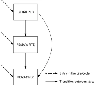
6.4.4 State Changes
This section describes the possible state changes (also called transitions) performed by the NFC Forum Device. Figure 4 shows the states and the transitions between them. The transitions are valid for static and dynamic memory structure. The possible transitions used by the NFC Forum Device for the Type 2 Tag Platform are:
• Transition from INITIALIZED to READ/WRITE • Transition from INITIALIZED to READ-ONLY • Transition from READ/WRITE to READ-ONLY
[RQ_T2T_NDA_024] The NFC Forum Device SHALL be able to perform the three transitions for static and dynamic memory structure.
NOTE A Type 2 Tag Platform might be issued in any valid state. So, a Type 2 Tag Platform might be issued in INITIALIZED state, READ/WRITE state, or even in READ-ONLY state that has a predefined NDEF message stored on it.
INITIALIZED
READ-ONLY READ/WRITE
Entry in the Life Cycle Transition between states Figure 4: Life Cycle with State Changes (transitions)
6.4.4.1 Transitions from INITIALIZED to READ/WRITE
[RQ_T2T_NDA_025] To perform the transition from INITIALIZED to READ/WRITE, the NFC Forum Device SHALL use the NDEF write procedure (see Section 6.4.3) to replace the empty NDEF Message TLV with a non-empty NDEF Message TLV (length field different from zero).
The NFC Forum Device MAY perform the transition only if the Type 2 Tag Platform is in INITIALIZED state; otherwise, it SHALL NOT perform it.
The transition from READ/WRITE to INITIALIZED is not defined. To delete or remove the NDEF message in NDEF Message TLV, the NFC Forum Device MAY write an empty NDEF message (see Appendix A).
6.4.4.2 Transitions from READ/WRITE to READ-ONLY
[RQ_T2T_NDA_026] To perform the transition from READ/WRITE to READ-ONLY, the NFC Forum Device SHALL set Byte 3 of the CC to 0Fh and all lock bits to 1b (including static and possible dynamic lock bits). To set bits and bytes, the NFC Forum Device MAY use one or more WRITE commands.
[RQ_T2T_NDA_027] The NFC Forum Device MAY perform the transition only if the Type 2 Tag Platform is in READ/WRITE state; otherwise, it SHALL NOT perform it.
[RQ_T2T_NDA_028] If the Type 2 Tag Platform has a dynamic memory structure as indicated by the CC byte 2 value bigger than 06h (see Section 6.1), the NFC Forum Device SHALL do the following operations to set to 1b the dynamic lock bits:
1. Check if any Lock Control TLV(s) is present in the data area.
2. If one or more Lock Control TLVs are present, set the dynamic lock bits identified by these Lock Control TLVs to 1b.
3. If no Lock Control TLV is present, set the dynamic lock bits identified by the default setting of the dynamic lock bits to 1b (see Section 2.2.2).
[RQ_T2T_NDA_029] For the WRITE command, the reading of not completely updated blocks SHALL be done by the NFC Forum Device first (see Section 5.2).
[RQ_T2T_NDA_030] If the data to be read or written exceeds one or more sectors, the NFC Forum Device SHALL use the SECTOR SELECT command (see Section 5.3).
6.4.4.3 Transition from INITIALIZED to READ-ONLY
[RQ_T2T_NDA_031] To perform the transition from INITIALIZED to READ-ONLY, the NFC Forum Device SHALL execute the following steps:
1. The transition from INITIALIZED to READ/WRITE (see Section 6.4.4.1) 2. The transition from READ/WRITE to READ-ONLY (see Section 6.4.4.2)
The NFC Forum Device MAY perform the transition only if the Type 2 Tag Platform is in INITIALIZED state; otherwise, it SHALL NOT perform it.
A.
Empty NDEF Message
An empty NDEF message (see [NDEF]) is defined as an NDEF message composed of one NDEF record. The NDEF record uses the NDEF short-record layout (SR=1b) with:
• Type Name Format (TNF) field value equal to 00h (empty, TYPE_LENGTH=00h • PAYLOAD_LENGTH=00h)
• No ID_LENGTH field (IL=0b) • MB=1b
• ME=1b • CF=0b
The empty NDEF record (i.e., the empty NDEF message) is composed of 3 bytes and it is equal to D00000h.
B.
Memory Structure Examples
This appendix shows two examples of memory structure: one for the static memory structure and one for the dynamic memory structure.
B.1 Example of Static Memory Structure
This section describes an example of static memory structure with 16 blocks. See Figure 5 for an example.
Byte Number 0 1
UID / Internal Internal0
2 3
Internal1 Internal2 Internal3
Serial Number Internal / Lock
CC
Internal4 Internal5 Internal6 Internal7
Internal8 Internal9 Lock0 = 00h Lock1 = 00h
NDEFMessage TLV0 = 03h
NDEFMessage TLV1 = 00h
TerminatorTLV0
= FEh Data3
Data4 Data5 Data6 Data7
Data8 Data9 Data10 Data11
Block 0 1 2 3 4 5 Data Data Data Data Data Data Data Data .. .. .. .. .. .. .. .. .. .. .. .. .. .. .. .. .. .. .. ..
.. .. Data46 Data47 CC0 = E1h CC1 = 10h CC2 = 06h CC3 = 00h
6 . . . . . 15 Data
Figure 5: Example of Static Memory Structure
If the Type 2 Tag Platform is in the INITIALIZED state, the overall memory is set as follows: • All lock bits are set to 0b: Lock0 = 00h and Lock1 = 00h
• The CC is set following Section 6.1:
• CC0 = E1h indicates that NDEF data is present inside the tag.
• CC1 = 10h indicates support for version 1.0 (major number 1h, minor number 0h) of the mapping document (i.e., the version of this specification).
• CC2 = 06h indicates 48 bytes of memory size assigned to the data area, dynamic lock bytes, and reserved bytes.
• The data area contains 2 TLV blocks in the following order: • NDEF Message TLV: empty TLV block
• T = 03h • L = 00h
• V = - (not present) • Terminator TLV:
• T = FEh
• L = - (not present) • V = - (not present)
B.2 Example of Dynamic Memory Structure
This section describes an example of dynamic memory structure with 32 blocks (k = 31) and 4 blocks of reserved data at the end of the physical memory. See Figure 6 for an example.
1 0
Internal0
2 3
Internal1 Internal2 Internal3 Internal4 Internal5 Internal6 Internal7 Internal8 Internal9 Lock0 = 00h Lock1 = 00h
LockControlTLV0
= 01h LockControlTLV1 = 03h LockControlTLV2 = E0h LockControlTLV3 = 06h LockControlTLV4
= 33h MemoryControl TLV0 = 02h MemoryControl TLV1 = 03h MemoryControl TLV2 = E1h MemoryControl
TLV3 = 0Fh MemoryControl TLV4 = 03h NDEFMessage TLV0 = 03h NDEFMessage TLV1 = 00h
Block 0 1 2 3 4 5 TerminatorTLV0
= FEh Data13 Data14 ..
.. .. .. .. .. .. .. .. .. .. .. .. .. Data93 Data94 Data95 Lock2 = 00h Reserved0 Reserved1 Reserved2
CC0 = E1h CC1 = 10h CC2 = 0Ch CC3 = 00h
6 7 . . . 27 28
Reserved3 Reserved4 Reserved5 Reserved6 29 Reserved7 Reserved8 Reserved9 Reserved10 30
Byte Number
UID / Internal Serial Number Internal / Lock
CC Lock Control TLV
Lock Control TLV / Memory Control TLV
Memory Control TLV / NDEF Message TLV Terminator TLV / Data
Data Data Data Data Lock / Reserved
Reserved Reserved
Reserved11 Reserved12 Reserved13 Reserved14 31
Reserved
If the tag is in the INITIALIZED state, the main memory area is set as follows: • All lock bits are set to 0b: Lock0 = Lock1 = Lock2 = 00h
• The CC is set following Section 6.1:
• CC0 = E1h indicates that NDEF data is present inside the tag.
• CC1 = 10h indicates support for version 1.0 (major number 1h, minor number 0h) of the mapping document.
• CC2 = 0Ch indicates 96 bytes of memory size assigned to the data area. • CC3 = 00h indicates read and write access granted without any security. • The data area contains 4 TLV blocks in the following order:
• Lock Control TLV: • T = 01h • L = 03h
• V = E00633h indicates that each lock bit locks 1 page, each page is 8 bytes, and the lock area is 1 byte long at the byte address:
ByteAddr = PageAddr*2BytesPerPage + ByteOffset = 14 * 23 + 0 = 112 where: • Position = E0h contains PageAddr = Eh and ByteOffset = 0h
• Size = 06h
• PageControl = 33h contains BytesPerPage = 3h (23 = 8 bytes) and BytesLockedPerLockBit = 3h (23 = 8 bytes).
• Memory Control TLV: • T = 02h
• L = 03h
• V = E10F03h indicates that the reserved area is 15 bytes long at the byte address: ByteAddr = PageAddr*2BytesPerPage + ByteOffset = 14 * 23 + 1 = 113 where: • Position = E1h contains PageAddr = Eh and ByteOffset = 1h
• Size = 0Fh
• PageControl = 03h contains BytesPerPage = 3h and most significant nibble = 0h (RFU, ignored)
• NDEF Message TLV: empty TLV block • T = 03h
• L = 00h
• Terminator TLV: • T = FEh
• L = - (not present) • V = - (not present)
The Lock Control TLV MAY be skipped using the default values for the dynamic lock area (see Section 2.2.2). Also, the Memory Control TLV can be skipped after the data area and after the dynamic lock area (see Figure 6 block 28-31).
C.
Examples of Command Flow
This section provides some examples of the command flow in order to show how a typical interaction can be performed. It is assumed that the Type 2 Tag Platform is in INITIALIZED or in READ/WRITE state. This example does not cover any checks of the NDEF message.
The commands and the responses are written in hexadecimal form with a space between each byte (e.g., 30 F3 AB 9C) without the “h” character at the end. The left-most byte is the first byte sent and the right-most byte is the last byte sent. Special acronyms like CRC0, CRC1, Data3, and Data11… are written to indicate a group of data or bytes with a specific meaning indicated later on in the description of the command or of the response.
C.1 Static Memory Structure Examples
The two examples in the following two sections are based on static memory structure (see Section 2.1).
C.2 Detection of NDEF Message
To detect the NDEF message, the NDEF detection procedure is applied (see Section 6.4.1). Two examples are given with a positive and a negative detection of NDEF message.
C.2.1
Positive Detection of NDEF Message
A READ command is issued to read blocks 3 to 6 (BNo = 3-6) of the static memory structure where the CC and NDEF Message TLV are located.
Command: 30 03 CRC0 CRC1 • The meanings of the bytes are:
• 30h indicates the READ command.
• 03h indicates to start to read from the block number (BNo). • CRC0 and CRC1 are the CRC bytes.
Response: E1 10 06 00 03 03 D0 00 00 FE Data6 … Data11 CRC0 CRC1
• The meanings of the bytes are (note that only the first four bytes belong to block 3 and to the CC):
• E1h = CC0 indicates that NDEF data is present inside the tag.
• 10h = CC1 indicates support for version 1.0 (major number 1h, minor number 0h) of the mapping document.
• 06h = CC2 indicates 48 bytes of memory size assigned to the data area. • 00h = CC3 indicates read and write access granted without any security. • 03h indicates that an NDEF Message TLV is present.
• 03h indicates that the value field of NDEF Message TLV is present (length equal to zero) and contains 3 byes.
• 0D0000h is an empty NDEF message (see Appendix A). • FEh indicates that the Terminator TLV is present.