Chapter 6
PERFORMANCE EVALUATION OF ORDER CYCLE OF
A MANUFACTURING INDUSTRY
This chapter focuses on design and development of order cycle software for manufacturing industry. To be competitive and responsive, organization should continuously improve their operations. An order fulfilment process function is a critical determinant of how well you satisfy, and therefore retain, your customers. So the order fulfilment process plays a crucial role. This chapter focuses on order fulfilment process or cycle and various parameters for measuring its effectiveness.
6.1 Role of IT in supply chain management
Information systems play the role of integration, co-ordination between different parts of the supply chain and the performance of this system has a direct impact on the efficiency of supply chain performance. Information technology can also support co-operation between companies and their internal co-operations in supply chain and effective use of technology is a key factor in the success of the company. Major cause of uncertainty is, poor information flow, which can include inaccurate, being premature or incorrect information management. Information technology with ability of managing information flow affect various dimensions of supply chain, such as cost, quality, flexibility and timely delivery of goods and services and ultimately the profit of organization.
The use of IT for optimizing SCM can be divided into
Transaction processing
Supply chain planning and collaboration
Order tracking and delivery coordination
Transaction processing stands for the use of IT for increasing the efficiency of repetitive information exchanges between supply chain partners. In this type of IT use, the exchanged information is typically related to such tasks, as, order processing, billing, delivery verification, generating and sending dispatch advices, and producing order quotes.
Supply chain planning and collaboration represents the use of IT for sharing planning-related information such as, demand forecasts and other demand information, inventory information, and production capacity information, with the intention of increasing the effectiveness of the supply chain.
Order tracking and delivery co-ordination refers to the monitoring of individual orders or shipments, which may consist of components or final products, with the aim of co-ordinating their delivery or conveying timely information of their location. This research is focusing on order fulfilment or order cycle process.
6.2 Order fulfilment process
An order fulfilment process (OFP) starts with receiving orders from the customers and ends with having the finished goods delivered. The order fulfilment cycle time is defined as the period from order receipt to product delivery. The order fulfilment process is complex, because, it is composed of several activities, executed by different functional entities, and heavily interdependent among the tasks, resources, and agents involved in the process. This process involves the co-ordination of diverse activities such as, sales commitment, manufacturing, logistics, accounts receivable, and relationships with external suppliers for purchasing or shipping, which normally take place in several different business units. The main activities of the OFP can be summarized as follows:
1. Order management, which receives orders from customers and commits order requests
2. Manufacturing, which includes production scheduling, material planning, capacity planning, and shop floor control
3. Distribution, which considers the logistics such as inventory and transportation.
The main objectives of the OFP can be generalized into two dimensions:
Delivering qualified products to fulfill customer orders at the right time and right place, and,
Achieving agility to handle uncertainties from internal or external
An order fulfilment process function is a critical determinant of how well you satisfy, and therefore, retain, your customers. So, the order fulfilment process plays a crucial role in supply chain management, and it is considered as the most important business process. This chapter focuses on the development of order fulfilment software that can be used by the small and medium-sized industries for order fulfilment process.
6.3 Order cycle software
Software is designed and developed to demonstrate the complete order fulfilment process starting with the receipt of order to fulfilling the order. A process of Bill of Materials (BOM) explosion was developed and incorporated. An overall flow chart of the order cycle process sequences and a graphical user interface (GUI) based software was developed using Dot net 2008 and SQL 2005. Evaluation tests of the software were carried out using various products ranging from those with simple structure of single product to complex structure with multiple products sharing common items. It was even validated for multiple suppliers for multiple products. The software was shown to be user-friendly and allows easy data input. Date and time validation was also incorporated in the software to make it more efficient.
6.3.1 Application Architecture
Application architecture is the science of designing an application to achieve certain goals, such as, performance and scalability. Partitioning the application by grouping all the entities logically based on certain guidelines is application design resulting in Application Architecture. The benefits of such design are:
The performance of the application is better; the applications will be scalable by being able to incorporate future requirements.
By partitioning an application into logical groups also called as layers results in a cohesive code. Such cohesive code is preferred because similar types of code are placed together and can be managed easily.
The layered based approach provides abstraction, allowing modifications at one
level without impacting or with minimal impact on other layers
Four layers are developed for the current software. They are: Data Layer, Data Access Layer, Business Layer and Presentation Layer.
A. Presentation Layer
In the Presentation Layer, the code responsible for displaying user interface of the entire application is located. The common codes placed in this layer are windows forms, web forms, user controls and server controls. Examples are data entry form for the manufacturing module and similar forms for all other modules. Note that Windows Forms are used for client interaction in desktop applications and web forms are for browser-based interaction. Also, note that an application developed based on the layered approach includes code for interaction between different layers. The code which provides interaction between the presentation layer and business layer is located in this layer. Basic validations which are implemented at the user interface level are also located in this layer. Some examples are checking for blank fields, negative numbers, and valid dates etc.
B. Business Layer
In the Business Layer, the code that implements the business functionality of the application is located. The business logic of application is implemented by using components. Business components encapsulate the business logic, also called business rules. These rules constrain the behavior of a business concept to match the needs of a particular company. Business processes are the activities that occur in a business. Examples are: order processing, bill of materials, issue of work order, creating invoice etc. These business processes are encapsulated in the business components. One business component may interact with one or more business components to implement a business process. The Business Layer also includes code responsible for accessing the Data Access Layer to retrieve, modify and delete data to and from the data layer and move the results to the presentation layer.
C. Data Access Layer
The Data Access Layer provides access to databases such as SQL Server, Oracle etc. The .NET technology used to provide data access functionality is ADO.NET. The application we are developing accesses data stored in the SQL server database, which is a relational database. The code in this data access layer exposes the data stored in the database to the business layer.
D. Data Layer
Data Layer is the database or the source of the data. We have used SQL server as the database for our application.
6.3.2 System Development
System Development involves materializing the process conceptualized in the preceding stage through the software interface development and algorithm coding. The coding consists of sets of instructions that are executed by the program when the user clicks on a control. The software has the interfaces in different forms. The design is done to ensure the ease of verification and correction of mistakes. Microsoft dot net was adopted in developing the software which is compatible with the Microsoft windows operating system.
The application uses four pieces of information to determine what material should be ordered and when and they are:
i. Order entry date and customer request date;
ii. Bill of materials, which lists exactly the parts or materials required to make each product;
iii. Production cycle times and material needs at each stage of the production cycle
time; and,
iv. Supplier lead times.
The master schedule and bill of materials indicate what materials should be ordered; the master schedule, production cycle times and supplier lead times then jointly determine when orders should be placed.
The Master Production Schedule includes quantities of products to be produced at a given time period. Bill of Materials gives information about the product structure, i.e., parts and raw material units necessary to manufacture one unit of the product of interest.
Fig. 6.1 6.3.2.1 Database Design
The impact of data structure on program structure and data design to have profound influences on software quality. The goals of database design are to:
Satisfy the information content requirements of the specific user and applications
Provide a natural and easy to understand
Support processing requirements and any performance objectives such as response
time, processing time and storage space Database management system
aggregation of raw data. I
establish links between tables offering easy access and maintenance of data observations and their relationships. In addition to numeric data manipulation, it allows parsing of textual
words (tokens) (Wolfram, 2006). Structured
to develop the SW application system. SQL is a DBMS that allows data in different ways through SQL da
language enables the requesting of information from a datab analyze data from different
The various tables created in the database are as shown in table. 6.1
Recieve order quantity from customer with all relevant details along
with order number
Goods Receipt Note
Job allotment
6.1: Process flow adopted in the software .2.1 Database Design
of data structure on program structure and procedural complexity causes data design to have profound influences on software quality.
The goals of database design are to:
Satisfy the information content requirements of the specific user and applications Provide a natural and easy to understand structuring of the information
Support processing requirements and any performance objectives such as response time, processing time and storage space.
atabase management system environment allows a flexible representation and aggregation of raw data. It provides the ability to create tables to house data and establish links between tables offering easy access and maintenance of data observations and their relationships. In addition to numeric data manipulation, it
strings for distinct words (types) and different occurrences of words (tokens) (Wolfram, 2006). Structured Query Language (SQL) database is used to develop the SW application system. SQL is a DBMS that allows the ability to view data in different ways through SQL data grouping. SQL as a standardiz
enables the requesting of information from a database making it possible to e data from different perspectives.
The various tables created in the database are as shown in table. 6.1
Accept or Deny the order by entering
order no and accepted or denied
number
Check inventory? Material Requirement Planning for the current order number
Send quotation different supplier for Approve quotation
based on supplier parameters Raise purchase order
to the selected supplier
Production plan Order delivery to the customer
procedural complexity causes
Satisfy the information content requirements of the specific user and applications. structuring of the information.
Support processing requirements and any performance objectives such as response
environment allows a flexible representation and tables to house data and establish links between tables offering easy access and maintenance of data observations and their relationships. In addition to numeric data manipulation, it
istinct words (types) and different occurrences of Query Language (SQL) database is used the ability to view grouping. SQL as a standardized query ase making it possible to
Material Requirement Planning for the current order number
Send quotation request from different supplier for
different Raw materials
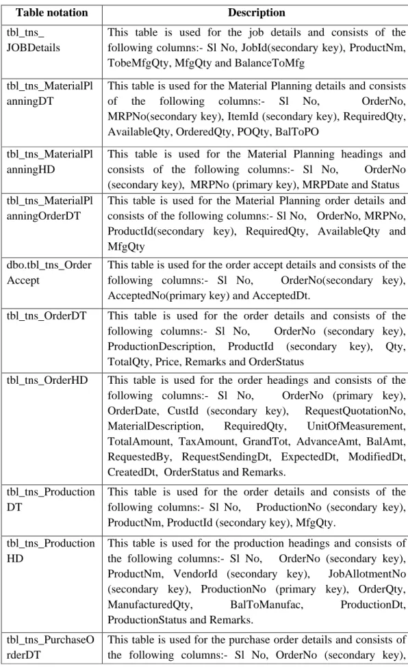
Table 6.1 Database Table Design Table notation Description
tbl_Mast_BOM Bill of Material table which consists of columns named as
product id, item id, Qty and TempID. tbl_Mast_Business
Partner
Business partner table which has details of both suppliers and customers. The different columns are Sl. No, Partner id which is a primary key, Name, address, Phone, Fax, email id, contact person and partner type.
tbl_Mast_Item The product details table which consists of Sl No., Item_code which is a primary key, Item name, Item description, Item type and price of the item.
tbl_Mast_Tax Tax table which consists of Slno, Taxcode which is a primary
key, Tax description, Taxpercentage. tbl_tns_GRNatFact
oryDT
Goods receipt at factory details table which consists of Sl No, Order no, PONum, GRNNo, MaterialID, Unit price, Qty, Total, Tax, Grandtotal, OrderQty, RecQty, BalQty and Remarks columns. Among these, Order no, PONum, GRNNo, MaterialID are secondary keys.
tbl_tns_GRNatFact oryHD
Goods receipt at factory header table which includes Sl No, Order no, PONum, GRNNo, GrnDt, SupplierNm, Description, Unit price, OrderQty, Tax, Grandtotal, RecQty, BalQty and Remarks columns. Among these, Order no, PONum, are secondary key and GRNNo, is the primary key.
tbl_tns_InvoiceDT This table is used for the invoice details and consists of the following columns:- Sl No, Order no, InvoiceNo, ItemNm, Unit price, OrderQty, TaxAmt, Grandtotal, TotalAmt and Remarks. Among these, OrderNo and InvoiceNo are secondary keys.
tbl_tns_InvoiceHD This table is used for the invoice headings and consists of the following columns:- Sl No, Order no, InvoiceNo, OrderDt, DueDt, DispatchDt, InvoiceAmt, TotalOrderQty, TaxAmt, Grandtotal, TotalAmt, DispatchStatus and Remarks. Among these, OrderNo is a secondary key and InvoiceNo is the primary key
tbl_tns_JobAllotm ent
This table is used for the job allotment details and consists of the following columns - Sl No, JobAllotmentNo (primary key), OrderNo(secondary key), JobAllotmentDt, DueDt, Description, OrderQty, MaterialID(secondary key), JobAllotmentStatus, SupplierNm and Remarks.
Table notation Description
tbl_tns_ JOBDetails
This table is used for the job details and consists of the following columns:- Sl No, JobId(secondary key), ProductNm, TobeMfgQty, MfgQty and BalanceToMfg
tbl_tns_MaterialPl anningDT
This table is used for the Material Planning details and consists
of the following columns:- Sl No, OrderNo,
MRPNo(secondary key), ItemId (secondary key), RequiredQty, AvailableQty, OrderedQty, POQty, BalToPO
tbl_tns_MaterialPl anningHD
This table is used for the Material Planning headings and consists of the following columns:- Sl No, OrderNo (secondary key), MRPNo (primary key), MRPDate and Status tbl_tns_MaterialPl
anningOrderDT
This table is used for the Material Planning order details and consists of the following columns:- Sl No, OrderNo, MRPNo, ProductId(secondary key), RequiredQty, AvailableQty and MfgQty
dbo.tbl_tns_Order Accept
This table is used for the order accept details and consists of the following columns:- Sl No, OrderNo(secondary key), AcceptedNo(primary key) and AcceptedDt.
tbl_tns_OrderDT This table is used for the order details and consists of the following columns:- Sl No, OrderNo (secondary key), ProductionDescription, ProductId (secondary key), Qty, TotalQty, Price, Remarks and OrderStatus
tbl_tns_OrderHD This table is used for the order headings and consists of the following columns:- Sl No, OrderNo (primary key), OrderDate, CustId (secondary key), RequestQuotationNo,
MaterialDescription, RequiredQty, UnitOfMeasurement,
TotalAmount, TaxAmount, GrandTot, AdvanceAmt, BalAmt, RequestedBy, RequestSendingDt, ExpectedDt, ModifiedDt, CreatedDt, OrderStatus and Remarks.
tbl_tns_Production DT
This table is used for the order details and consists of the following columns:- Sl No, ProductionNo (secondary key), ProductNm, ProductId (secondary key), MfgQty.
tbl_tns_Production HD
This table is used for the production headings and consists of the following columns:- Sl No, OrderNo (secondary key), ProductNm, VendorId (secondary key), JobAllotmentNo (secondary key), ProductionNo (primary key), OrderQty,
ManufacturedQty, BalToManufac, ProductionDt,
ProductionStatus and Remarks. tbl_tns_PurchaseO
rderDT
This table is used for the purchase order details and consists of the following columns:- Sl No, OrderNo (secondary key),
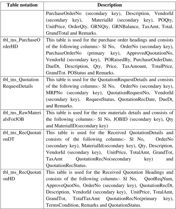
Table notation Description
PurchaseOrderNo (secondary key), Description, VendorId (secondary key), MaterialId (secondary key), POQty, UnitPrice, OrderQty, GRNQty, GRNBalance, TaxAmt, Total, GrandTotal and Remarks.
tbl_tns_PurchaseO rderHD
This table is used for the purchase order headings and consists of the following columns:- Sl No, OrderNo (secondary key),
PurchaseOrderNo (primary key), ApprovedQuotationNo,
VendorId (secondary key), PORaisedBy, PurchaseOrderDate, DueDt, Description, Qty, Price, TaxAmount, TotalPrice, GrandTot. POStatus and Remarks.
tbl_tns_Quotation RequestDetails
This table is used for the QuotationRequestDetails and consists of the following columns:- Sl No, OrderNo (secondary key), MRPNo (secondary key), QuotationRequestNo, VendorId (secondary key), RequestStatus, QuotationRecDate, DueDt, and Remarks.
tbl_tns_RawMateri alsForJOB
This table is used for the raw materials details and consists of the following columns:- Sl No, JOBID (secondary key), Qty and MaterialID(secondary key)
tbl_tns_RecQuotati onDT
This table is used for the Received QuotationDetails and consists of the following columns:- Sl No, OrderNo (secondary key), MaterialId(secondary key), Qty, Description, VendorId (secondary key), UnitPrice, TotalAmt, GrandTot,
TaxAmt QuotationRecNo(secondary key) and
QuotationRecStatus. tbl_tns_RecQuotati
onHD
This table is used for the Received Quotation Headings and consists of the following columns:- Sl No, QuotReqNum, ApproveQuotNo, OrderNo (secondary key), QuotationRecDt, Description, VendorId (secondary key), UnitPrice, TotalAmt,
GrandTot, TotalTaxAmt QuotationRecNo(primary key),
TermsCondition, Remarks and QuotationStatus.
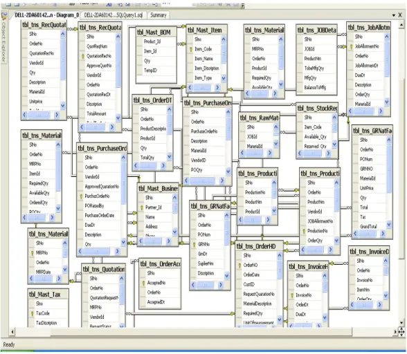
Entity Relationship diagram
An Entity Relationship Diagram (ERD) is a model that identifies the concepts or entities that exist in a system and the relationships between those entities. An ERD is often used as a way to visualize a relational database: each entity represents a database table, and the relationship lines represent the keys in one table that point to specific records in related tables. ERDs may also be more abstract, not necessarily capturing every table needed within a database, but serving to diagram the major concepts and relationships. The entity relationship diagram is as shown below in Figure 6.2
Fig. 6.2: Relationship diagram 6.3.2.2 System flow sequence
The sequence of process flow or data flow is as follows. Note that after every step the application form is to be saved with the appropriate button. Once the fully filled form is saved, a message stating that the transaction is successfully completed is displayed. This is repeated in all the forms. If there is any error in the form, it is displayed instead of the message. Until and unless the error is rectified, further execution is impossible.
1. An order number is automatically generated once the form is displayed. The user
(customer) specifies his contact details and places an order for the existing product mentioning the due date. Date validation is done to ensure that the system takes the perfect dates. Once the quantity is mentioned, the software calculates the amount including the tax and displays it as shown in screenshot of Figure 6.3
2. The software automatically generates new id for new order, new customer, new quotation, new purchase order, job allotment and production. A sample of the code used for the same is shown in Appendix E;
3. The manufacturer accepts / denies the order based on the availability and lead time (due date). Once this form is opened the order number can be selected from the list and can be accepted or rejected. If rejected, the order is cancelled and no further process can be executed for that order. If accepted, an order accepted number is generated automatically.
Fig. 6.3 Screen shot of order details
4. If the manufacturer accepts the order, the order number in available in Material requirement planning (MRP) which is the next step, if not the order ceases. In the reports, we can see the status as order denied. An MRP number is generated with the MRP date if the order is accepted. In the MRP form the order number appears and the software shows the order details including the inventory details and to be manufactured details, BOM of the product and also the available raw material for manufacturing the same as shown in Figure 6.4. If an order is created and is not fulfilled and suppose a new order is generated, even though the product is available it will be reserved for the “yet to be filled order”. The code used for calculating inventory details and to be manufactured is as shown in the Appendix E.
Fig. 6.4 – Screen shot of MRP Details
5. In the quotation request form, the MRP number appears, which when selected, displays requested quotation number, order number, Quotation Request Date and due date. It also shows the MRP details, which includes the quantity to be ordered and lead time and displays the suppliers list for those materials. A check box is provided to select the supplier. Multiple suppliers can be selected and quotation request can be sent to all of them as shown in Figure 6.5.
6. In the received quotation form, quotation number is displayed along with the supplier’s name. Each supplier can be selected and the order number along with terms and conditions of the supplier is displayed in this form. Once a particular supplier is selected, the unit price sent by them should be entered by the user. An automatic received quotation number for supplier will be generated. The system generates the grand total including tax. This is repeated for all the suppliers.
7. In the approved quotation form, all the suppliers who have quoted can be approved or only the supplier who has quoted the lowest price can be selected from the list of suppliers and approved. An automatic approved quotation number is generated.
Fig. 6.5 – Screen shot of Quotation request Details
8. A purchase order is raised for the approved supplier with an approved quotation number and the order number. A Purchase Order (PO) number is generated and purchase order date should be selected. This form displays the details of the supplier and the order details. The purchase order quantity needs to be entered. Purchase order can be placed with multiple suppliers,
9. In the goods receipt note the GRN No is generated for the selected Purchase order number. The quantity received from the supplier for a particular date should be entered. The quantity can be received in multiple batches as practised in most of the organizations. Until the complete material quantity is received, further processing is not done. Once all the raw material is received, job allotment starts. Separate GRN is generated each time material is received from each supplier. 10. For a selected order, the job allotment number is generated along with the due date
mentioned. The job allotment date needs to be entered. This form displays the BOM along with the order raw material details as shown in Figure 6.6
11. In production details form, for a selected job number the order number is displayed along with the due date. The production number is generated and the user needs to enter the production date along with the quantity manufactured.
12. In order delivery, an invoice number is generated for the selected order number along with the order and due date. Invoice date along with delivery date need to be entered. Customer details will be automatically generated as shown in Figure 6.7.
Fig. 6.6 : Screen shot of job allotment details
Fig. 6.7: Screen shot of order delivery details 6.3.3 Systems Testing
A critical step in the system development process, system testing and debugging, revolves around ascertaining the integrity of the system output. System testing and debugging of software was done to identify errors and possible areas of improvements in the software. For ease of future improvement and maintainability comments on each block of codes are included. Evaluation tests of the software were carried out using various products ranging from those with simple structure of single product to
complex structure with multiple products sharing common items. It was even validated for multiple suppliers for multiple products. The software was shown to be user friendly and allow for easy data input.
6.4 Results
The results after implementing the order fulfilment software can be identified among three main dimensions, namely: inventory, priorities and capacity:
Dimension Objective specifics
Inventory: - Order the right part
- Order the right quantity - Order at the right time
Priorities: - Order with the right due date
- Keep the due date valid
Capacity: - Plan for a complete load
- Plan for an accurate load
- Plan for an adequate time to view future load
The following are the changes that are resulting after the software implementation in a company using manual order processing cycle:
1. Paper work gets reduced, and manual errors are completely eliminated,
increasing accuracy of the system and also reducing the general administration costs – This is due to the automation of the entire process.
2. Reduction of Inventory – As the components ordered as and when required and the product is manufactured after the receipt of the order, both raw material and finished goods inventory reduces drastically. This has an effect on inventory carrying costs as well on the space requirement of the company.
3. Delivery performance – The ability to meet delivery dates improves as the visibility of the entire process increases.
4. Reduction in processing time of information.
5. Ease of material requirement planning as Bill of Materials Explosion was included in the software.
All of the above mentioned factors results in reduction of purchasing costs, manufacturing costs, factory space, inventories, quality costs and cycle times which tends to improve the performance of the organization.
The report generated indicates the status of the order on the basis of time.. 6.8 indicates the number of orders
number of orders in process.
Fig. 6.8 Report generated
Summary
This chapter focused on
application architecture, database design of the software, entity relationship diagram is explained in detail. The process flow sequence adopted in the application is elaborated with the help of screen shots. Finally the results
No of orders fulfilled No of orders denied No of orders in process
generated indicates the status of the order on the basis of time.. the number of orders a company has fulfilled, orders denied number of orders in process.
Fig. 6.8 Report generated on order status
focused on software development for order fulfilment cycle. The application architecture, database design of the software, entity relationship diagram is explained in detail. The process flow sequence adopted in the application is
of screen shots. Finally the results are discussed.
0 1 2 3 4 5 6
No of orders fulfilled No of orders denied No of orders in process
generated indicates the status of the order on the basis of time.. Figure company has fulfilled, orders denied and
software development for order fulfilment cycle. The application architecture, database design of the software, entity relationship diagram is explained in detail. The process flow sequence adopted in the application is
discussed.