TECHNICAL UNIVERSITY OF CLUJ-NAPOCA
ACTA TECHNICA NAPOCENSIS
Series: Applied Mathematics, Mechanics, and Engineering Vol. 61, Issue I, March, 2018
CUTTING PARAMETERS AND ANALYSIS BY FEA SIMULATION OF
THEIR INFLUENCE ON THE RE-PROFILATION OF THE WHEELS OF
THE RAILWAY WHEELSET
Ionuţ Gabriel GHIONEA, Adrian GHIONEA, Nicolae PREDINCEA
Abstract: Modern approaches on research projects in the field of lathes’ remanufacturing involve various simulation stages, like FEA and CAM, in order to obtain results and solutions with different aspects and data important to consider. These simulations may confirm data obtained through measurement, but also extrapolate values that can’t be measured directly on the machine-tool technological system. Usually, a mathematical and simulated models, with a low error percent, are the main key for the remanufacturing team. The newest trend in manufacturing technologies, the acclaimed Industry 4.0, relies on new design concepts and methods, data acquisition and exchange between systems, processing, visualization and automation. Modern simulation methods, system integration between simulated and measured data, augmented reality, etc., are important parts of the actual factories. More and more machine-tools without CNC capabilities are remanufactured in this new vision of Industry 4.0. This paper presents some phases in establishing the turning process parameters in profiling and re-profiling of the trains wheelsets. There are used specific instruments (a mathematical approach and 3D models for FEA simulation) in order to determine which system (tool holder – insert – process parameters) are better to be used on the remanufactured lathe.
Key words: tread profile, wheelset, re-profilation, cutting parameters, FEA analysis.
1. INTRODUCTION
Wheelsets are the most loaded components of railway vehicles and subject of a continuous process of wearing resulted from different and difficult running conditions: non-uniform loads of the freight wagons, alteration of rail and wheel profile, sudden temperature variations, curved segments of rails, breakings, etc. Periodically, the wheelsets are checked and once they reach a critical level of wear, they must be reshaped or even replaced.
The replacement is difficult and occurs only when the material to be removed by cutting processes surpass a certain limit [1].
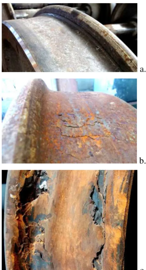
In figure 1 there are presented three samples of used wheels with different wear grades: normal, medium and very worn. In the last sample, the rolling surface may be reshaped after an analysis. If the wear includes also deep cracks, the reshaping process cannot be achieved and the wheelset will be replaced.
a.
b.
c.
The specialized lathes for processing the wheels and wheelsets of the railway vehicles are modernized according to the requirements of international standards and norms [2, 3, 4, 5]. The operation/movement of the railway vehicle involves the contact between the rail and wheels surfaces. In time, these surfaces become worn, leading to changes of the wheels profiles and, therefore, to instability in the movement of vehicles, an important problem for traffic safety and passengers comfort.
Due to the very high cost for acquisition of a modern new lathe, the companies often opt for the remanufacturing of an existing machine tool. Thus, they search and invest in the development and implementation of an automated equipment suitable for simulation, manufacturing and measuring of wheels running profile, both static and dynamic.
The remanufactured lathe has new driving, command and measurement systems and the costs are soon recovered by increasing the productivity and profiling/re-profiling accuracy, with the life of the lathe highly increased [6]. Our theoretical and experimental studies of cutting the alloyed steels are important in actual approaches [7, 8]. Such research generates important data on the theory of cutting, development and use of new cutting tools, rigidity increase of the technological system components, reducing processing times and of energy consumption [9].
The knowledge of the phenomena that characterize the chip formation and detachment, the quality and condition of the processed surface and the wear of the cutting tools is ensured by numerous researches.
The machinability of steel alloys differs depending on composing elements, heat treatments and manufacturing processes (cast, forged, etc.) [10, 11, 12].
The evaluation of roughness determined by the quality of the surface is the result of how the surface is generated [13].
The geometry of the cutting edge (constructive and active), the parameters of the cutting process, the vibrations, the elastic failures, the thermal phenomena, chip formation etc. are also important.
The components of the machining system are: the machine-tool subsystem, semi finished parts,
fixture devices, cutting tools, measuring and control devices.
2. SETTING THE PARAMETERS OF THE CUTTING CONDITIONS
The profiling and re-profilation of the wheels are carried out by technological processes of turning on specialized machine tools [1, 14]. Three types of machine tools are used, namely: conventional, portal and underfloor.
The main turning conditions for rolling surfaces are the following: the difference in diameters on the reference circle at the two wheelset’s wheels ∆D ≤ 0.15 mm, the profile
accuracy ≤ 0.15 mm, the roughness of the
surface Rz = 10 ... 20 µm, runout of the tread ≤
0.15 mm [3, 13].
Usually, the wheels have the diameter in certain dimensional domains, which are established and used for international transport vehicles intended for passengers. Diameter values may vary from minimum to maximum, as follows: 330-390 mm, 390-470 mm, 470-550 mm, 550-630 mm, 630-680 mm, 680-760 mm, 760-840 mm, 840-920 mm and 920-1000 mm, according to standards. These dimensions are imposed for both locomotives and wagons. The wheels’ geometry and dimensions are indicated in European standards in their annexes [4, 5].
2.1 Materials for wheels and turning tools
The steel materials used for wheels and rails across Europe have predominantly pearlitic structures containing hard cementite lamellae for a high wear resistance. A pearlitic microstructure, ensures a better resistance than bainitic or martensitic structures.
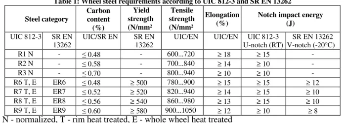
Although the standard UIC 812-3 [2] for solid wheels lists seven types of steel, which mainly differ in carbon content, heat treatment state and strength, the actual S R EN 13262 [ 4 ] contains only four types.
Table 1: Wheel steel requirements according to UIC 812-3 and SR EN 13262
Steel category
Carbon content
(%)
Yield strength (N/mm² )
Tensile strength (N/mm² )
Elongation (%)
Notch impact energy (J)
UIC 812-3 SR EN 13262
UIC/SR EN SR EN 13262
UIC/EN UIC/EN UIC 812-3 U-notch (RT)
SR EN 13262 V-notch (-20°C)
R1 N - ≤ 0.48 - 600...720 ≥ 18 ≥ 15 -
R2 N - ≤ 0.58 - 700...840 ≥ 14 ≥ 10 -
R3 N - ≤ 0.70 - 800...940 ≥ 10 ≥ 10 -
R6 T, E ER6 ≤ 0.48 ≥ 500 780...900 ≥ 15 ≥ 15 ≥ 12
R7 T, E ER7 ≤ 0.52 ≥ 520 820...940 ≥ 14 ≥ 15 ≥ 10
R8 T, E ER8 ≤ 0.56 ≥ 540 860...980 ≥ 13 ≥ 15 ≥ 10
R9 T, E ER9 ≤ 0.60 ≥ 580 900...1050 ≥ 12 ≥ 10 ≥ 8 N - normalized, T - rim heat treated, E - whole wheel heat treated
The choice of the cutting tools requires specific conditions, established by theoretical and experimental research, significant being those indicated by the main producing companies (Sandvik Coromant, Widia, Pramet, Iscar, Stellram, Ceratizit, Toprail).
For normal wear of the tread, the profile is processed in a single pass, and in other cases, the machining allowance is removed in two or more passes according to the specified machining conditions (dimensional precision, surface quality, profile and position deviations of the tread) [15]. The cutting tools system for re-profiling the railway wheels consists of turning tools with replaceable supports for tangentially mounted inserts. According to the companies recommendations, these inserts are able to withstand complex stresses at mechanical machining specific to turning, with high cutting depths, at high temperatures [12, 17].
The turning tools and their inserts are chosen according to the type of re-profiled wheel, the steel category (Table 1), the wheels wear condition, technical conditions of machining, the lathe version (e.g. RAFAMET UBC 150, Polish made, presented in figure 2), stability of the technological system, installed power of the machine-tool.
Fig. 2. Front view of the RAFAMET UBC 150 lathe
The machining of the two wheels composing the wheelset is done on the same machine tool in a single grip. There are used cutting tools with identical inserts, one on the left, the other on the right and the same cutting parameters.
The modular construction [17, 18] of the cutting tools indicates the high degree of technical characteristics and performance. For the tool choice it is taken into account the shape of the processed surface, the insert type (square, round or triangular), their number (one or two) and the producing company.
The insert’s shape and type are chosen depending on the machining process (roughing, semi finishing, finishing), current status of the surface and the requirements imposed by the fragmentation of the chips, also depending on cutting depths and feeds.
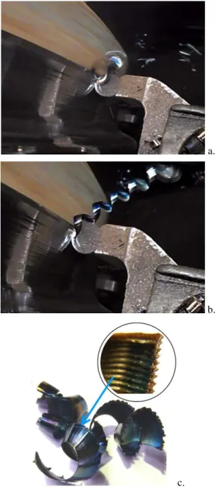
Thus, figure 3, a. shows fragmentary chips obtained in the machining process of the wheel surface of a wheelset (Fig. 2) at UV Aiud (the wagons factory of Aiud, Romania).
The main processing parameters according to figure 3 are: the wheel material is ER7 (242 … 276 HB), cutting speed vc = 38 m / min, cutting
depth ap = 7 mm, the cutting tool has a round
insert (diameter Dc = 20 mm) without cooling.
The chip type (continuous or segmental) is determined by numerous parameters, including the hardness of the material to be turned for re-profiling.
A segmented chip is also recommended to avoid wrapping it in the working area. Long chips also mean machine-tool idle time and an operator to clear the chips.
wear area, the chips result in segmentation. In figure 3, b. there is observed a spiral and continuous long chip obtained during the same turning process, but in a flattened layer area (fig. 1, a.), with a larger machining allowance, the wheel material in the respective area having a bigger wear and hardness. In figure 3, c. some segmental chips are exemplified.
The cutting process is not stable since the machining addition is uneven in size and hardness. These increase the tool wear, vibrations accompanied by specific noise. All this results from the analysis of the shape and appearance of chips (intense blue color and serrated edges, fig. 3, c. detail).
a.
b.
c.
Fig. 3. Sample of chips
One of the common problems in wheels re-shaping is the chip formation during the back turning operation at the rim zone. Most of the inserts have a specialized chip former that has been designed [19] to prevent long/continuous chip formation during the turning process. The choice of the inserts’ material is based on the condition of deterioration/wear of the wheel surfaces, the insert’s codification being specific to each tool producing company.
Thus, these grades [17, 18] are classified depending on the tread’s state of wear: for wheels with a low wear, it is used the ISO-P: GC3015 grade (high cutting speeds for maximum productivity).
Most wheels have some flattening and/or exfoliation areas, thermal cracks, small breaks, so it is used the ISO-P: GC4215 grade (it is almost universal, recommended as the first choice for all re-profilation processing).
In the case of the wheels with serious damaged areas, it is recommended to use the ISO-P: GC4225 or ISO-P: SH grades and turning at low cutting speeds.
For the analysis of the cutting parameters, two types of turning tools are considered: with square plates and with round plates. The tools bodies differ according to the shapes and dimensions of the inserts, an example being shown in figure 4 (with the main cutting edge on the right). It is also considered whether the processing of the rolling surface (the specific areas of the profile [3]) is done or not with the same tool.
Fig. 4. Sample of a turning tool
• semi finishing re-profilation of the excessively worn wheels, using a tool holder support fitted with two tangentially mounted inserts;
• finishing re-profilation of the low worn wheels using a tool holder support with two rhombic inserts;
• roughing re-profilation of wheels with an increased wear using two turning tools with square or triangular inserts;
• roughing re-profilation of the excessive worn wheels using a single turning tool with a round insert.
2.2. Roughness and cutting feed
The surface roughness is determined by the shape, state and dimensions of the main cutting edge of the insert and of the value of the cutting feed. This parameter is determined by the precision and the prescribed quality of the processed surface [20].
Also, in the determination of the feed, there are taken into account the technical conditions for machining [12, 19] of the wheels profiles. The surface roughness Ra, according to the feed
rate [14], is: Group I: Ra = 6.3 µm; Group II: Ra
= 12.5 µm.
There is a direct link [12] between the Ra and
Rt roughnesses and it can be considered a
constant ratio kR = Ra / Rt = 0.25.
Therefore, for the two groups mentioned, the theoretical roughness Rt has the value: Group I:
Rt = 25 µm; Group II: Rt = 50 µm.
Knowing that at turning, the theoretical roughness of the machined surface for turning tools with peak radius rε is given by the relation:
ε n t
r f R
⋅ ⋅ =
8 10
2 3
[µm], (1)
the optimal feed is determined by the condition:
adm z z
t R R
R ≡ ≤
(
3)
1/210
8 ε zadm
opt r R
f ≤ ⋅ − ⋅ ⋅ [mm / rot], (2)
where Rz is the average roughness, in µm.
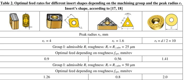
The peak radius having different values depending on the shape of the insert and considering the admissible Rz roughness
according to the two processing groups, the optimum values for the feed are obtained and indicated in Table 2.
Table 2. Optimal feed rates for different insert shapes depending on the machining group and the peak radius rε
Insert’s shape, according to [17, 18]
Peak radius rε, mm
rε = 4 rε = 1.6 rε = d / 2 = 10
Group I:admissible Rz roughness: Rt = Rz adm = 25 µm
Optimal feed depending on roughness fopt, mm/rev
0.9 0.56 1.41
Group I:admissible Rz roughness: Rt = Rz adm = 50 µm
Optimal feed depending on roughness fopt, mm/rev
1.26 0.8 2.0
Note: The values set for the fopt parameter can be diminished by a certain factor that takes into account the static and
dynamic behavior of the technological system. The recommended value is also determined by experimental research.
Analyzing the values in Table 2 according to the peak radius and admissible Rz adm, it is found
that these values are in accordance with the values indicated in the catalogs of the companies producing the cutting tools.
In these conditions, the minimum feed value is adopted: fmin = 0.3 mm/rev. For the maximum
feed value fmax in the roughing process of the
wheel profile, the value fmax = 2 mm/rev is also
2.3. Setting the cutting speed
For the determination of the cutting speed vc,
a calculus relation is presented, taking into account the following parameters: effective durability T, cutting depth ap and feed fn [8, 21].
The durability is adopted at the value T = 120 min, imposed by the processing of a suitable number of wheels, considering an average productivity of the process. Thus, it is considered: g G E n E p
c=C a f T K
v ⋅ ⋅ ⋅ ⋅ [m/min], (3)
where the constant C and the exponents F, E and G depend on the processing group (Table 1), on the pair of materials cutting tool-wheel; Kg -
global correction factor that takes into account the machinability and rigidity of the machine-tool - machine-tool - fixture device - part system.
Thus, for the wheels material, it is considered the group of alloyed steels with chromium, nickel and molybdenum, with the yield strength Rm = 1000 N/mm2, that is included in the
processing Group 7 (Table 1).
The machining is done with a sintered metal carbide turning tool with thin-film coatings (grade GC 4215). This coated carbide grade is used for finishing to roughing in applications with continuous cut to light intermittence of steel and steel castings. It presents a gradient substrate optimized in hardness and toughness with a wear resistant coating.
The GC 4215 grade is able to withstand high temperatures without sacrificing edge line security in wet and dry applications. According to [21] the values are admitted: C = 168; E = 0.45; F = -0.12; G = - 0.16 for use in relation (3). The following parameters for the machining conditions are considered: ap = 8 mm; fn = 1.2
mm/rev and a value of the correction coefficient Kg = 0.75.
Through replacements and calculations it is obtained the value of vc≅ 45 m/min, which is the
main recommendation of the companies producing cutting tools.
For finishing processing, the considered parameters are: ap = 3 mm; fn = 0.5 mm/rev and
a correction coefficient Kg = 0.8. By replacing in
relation (3), it is obtained: vc≅ 75 m/min.
2.4. Range of cutting speed and feed rates
The minimum and maximum values of the wheels diameters subjected to re-profiling are considered to be: Dmin = 630 mm; Dmax = 1300
mm, then results the maximum and minimum spindle speed (nc) of the main shafts that support
and drive the wheelset, namely:
38 630 75 1000 1000 ≅ ⋅ π ⋅ = ⋅ π ⋅ = min max c max c D v
n [rev/min]; (4)
11 1300 45 1000 1000 ≅ ⋅ π ⋅ = ⋅ π ⋅ = max cmin min c D v
n [rev/min]; (5)
Thus, the spindle speed variation range is determined Dnc = nc min ... nc max = 11 ... 38
rev/min. The remanufactured lathe has: Dn = nmin
... nmax = 9 ... 35.5 rev/min. The range is achieved
by a combined adjustment mechanism that consists of a two-speed asynchronous electric motor and a four-speed gearbox with the ratio of
φ = 1.41.
The feed speed range Dvf is based on the
values of the feed parameters (fmin and fmax) and
of the spindle speed (nc min and nc max) as follows:
11 38 3 ,
0 ⋅ ≅
= ⋅
= min cmax
min
f f n
v [mm/min]; (6)
22 11 0 ,
2 ⋅ =
= ⋅
= max cmin
max
f f n
v [mm/min]. (7)
2.5. The cutting forces
The identification of the cutting forces values is useful both for the design and for the functioning of the lathe. Thus, for the design of the main shaft assembly, data are needed to dimension its structural elements (shaft, bearings, clamping and drive mechanisms). It is necessary to determine the components of total cutting resistance and moment of cutting. The components of the total cutting resistance F [22], called cutting forces and defined according to the working plane are obtained by projecting the force F on the axes of the OXYZ kinematic reference system. These are:
Fc - the cutting force required for dimensioning
of the main shaft;
Ff - the feed force required for dimensioning the
components of the kinematic chain of feed/positioning, with the speed vf,
Fp –the passive force required to dimensioning
In literature [15] there is a multitude of mathematical relations theoretically or experimentally determined, which can lead to results with different values.
Thus, the cutting force is determined by the calculation relation [21]:
prd uz ms v o c
m prd
uz ms v o c
c b h k K K K K K b h k K K K K K
F = ⋅ ⋅ ⋅ γ ⋅ ⋅ ⋅ ⋅ = ⋅ 1− ⋅ 1.1⋅ γ ⋅ ⋅ ⋅ ⋅ [N], (8)
in which: m - a polytropic exponent; Kγo -
correction factor depending on the orthogonal departure angle γo; Kv - correction factor
according to the cutting speed; Kms = 0,95...0,9 -
correction factor depending on the material of the cutting tool insert; Kuz = 1,3...1,5 - correction
factor according to the wear of the cutting tool edge; Kprd - correction factor according to the
machining process, h – chip thickness.
Between the specific cutting force and the specific cutting resistance, the calculation relation is established:
m c c
h k
k = 1.1 [N / mm2]. (9)
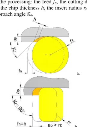
Figure 5 shows some basic geometric parameters of the insert (a. round insert and b. rectangular insert) and technological parameters of the processing: the feed fn, the cutting depth
ap, the chip thickness h, the insert radius rε, the
approach angle Ƙr.
a.
b.
Fig. 5. Parameters notation of two inserts types
The feed force Ff and the passive force Fp are
determined with similar relations (10) as that of the cutting force Fc:
x f
f b k h
F = ⋅ 1.1⋅ 1− [N]; Fp b kp h y
−
⋅ ⋅
= 1.1 1 [N]. (10)
The values for the polytropic constants and exponents [8, 21] were considered for the 30CrNiMo8 wheel material: m = 0.2, kc1.1 =
2600 [N/mm2], 1-x = 0.38, k
f1.1 = 355 [N/mm2],
1-y = 0.57, kp1.1 = 255 [N/mm2]. The material has
characteristics close to those of the wheel (ER7). The chip thickness h is determined by the relations established between the geometrical and technological parameters (Fig. 5). Also, using these chip parameters, there are determined the cross section area A, the chip rate Q and the machining productivity.
h b f a
A= p⋅ n = ⋅ [mm2]. (11)
The detached chips rate Q is determined depending on the machining process. When turning, the calculation relation (12) is used:
f p m c
c n
p f v A v d a v
a
Q= ⋅ ⋅ = ⋅ =π⋅ ⋅ ⋅ [cm3/min].(12)
The corresponding time for a pass is determined using the calculus relation:
c n
z c
n f
l t
⋅
= [min] (13)
where: lz (mm) is the length of the machining
stroke.
3. ANALYSIS BY FEM SIMULATION OF THE MACHINING PROCESSES
In order to study the static and dynamic behavior [23, 24] of the assembly insert – tool holder - radial sledge in the case of using certain tools recommended by the producing compa-nies, the finite element method is used.
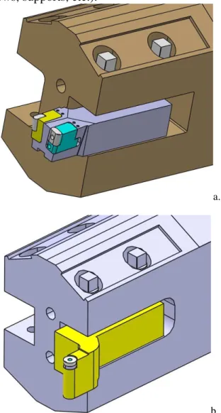
with round plate (fig. 6). The components were assembled geometrically by applying specific constraints of coincidence, contact, parallelism, linear distance, etc.
The dimensions required for the modeling were taken from tools, tool holders and inserts catalogs, but also through direct measurements of other components (radial sledge, clamping screws, supports, etc.).
a.
b.
Fig. 6. Tool holders: with square and round inserts
In each case, the meshing of the studied assembly was made by establishing conditions specific to the FEM analysis to obtain a finite structure.
The loads and deformations at a certain number of points within the assembly are sufficient to accurately characterize its mechanical behavior.
The finite element method calculates the displacements and tensions only at these points of the created mesh, and the meshing process must provide a sufficient number of points in the
areas of interest in order to obtain a satisfactory approximation of the structure's geometry and loading conditions [24].
To the components of each assembly have been applied specific materials, according to the catalogs and standards, the most important parameters and a determinant role in the FEM simulation being Young's module, yield strength and density.
Thus, the component materials are considered as follows (in N/mm2): Tool holder
4.2×10⁸, Inserts seats 3.8×10⁸, Inserts 5.2×10⁹,
Radial sledge 2.8×10⁸, Clamping screws
2.5×10⁸, Insert's guide rail 2.2×10⁸.
Based on the work parameters previously determined by the calculations results the cutting forces occurred during the machining process. These forces were applied to the cutting edges of the inserts and load the whole assembly.
In the FEM analysis performed for its validation, several different situations are considered, varying the cutting depth and feed rate, but there are also considered the machining material, the angle of the insert and the required cutting power of the machine tool [25].
Thus, the values of the cutting forces are obtained for roughing, semi finishing and finishing. The four cases considered are presented in Table 3.
The application of force is done in each case on the insert's edge, in a precise, but small area, experimentally determined.
To perform the specific calculations of the FEM analysis, it was used a computer with Windows 8.1 64 bit, 16 Gb RAM and i7 processor, the average time of each of the four iterations being about 5 hours.
The relatively high duration of each FEM simulation was due to the complex conditions imposed on the components, but also to their high discretization, resulting in relatively low error rates (between 13.48% and 18.44%). These values are lower than 20% and are considered acceptable for this assembly.
components with higher displacements (insert, seat, tool holder, etc.) are observed.
The displacements values are small and do not affect the manufacturing precision and measurement. It is noted that the maximum
displacement appears on the insert's cutting edge [23].
For example, in the case of roughing with a cutting force of 17744.64 N, the displacement value for the round plate is 0.12 mm.
Table 3. Values of the cutting forces for different machining processes
No. Processing Cutting depth, ap, mm
Feed, fn, mm/rev
Cutting force, Fc, N
Square insert Round insert
1 Finishing 3 0.3 3132.62 3358.74
2 Semi finishing 4.5 0.6 7375.91 8482.56
3 Roughing 1 6 0.65 11970.62 11853.33
4 Roughing 2 7 0.9 17229.4 17744.64
Table 4.Stresses values of the main components of the two assemblies radial sledge – tool holder - insert
Part Stress, N/m2 Displacement, mm
Machining process Yield strength Square insert Round insert Square insert Round insert
Tool holder 4.2×10⁸ 1.49×10⁸ 7.49×10⁷ 0.0182 0.0164
Finishing Insert seat 3.8×10⁸ 6.1×10⁷ 7.92×10⁷ 0.0189 0.0182
Insert 5.2×10⁹ 4.52×10⁸ 4.7×10⁸ 0.0239 0.0243
Radial sledge 2.8×10⁸ 2.01×10⁷ 2.6×10⁷ 0.0043 0.0037
Tool holder 4.2×10⁸ 3.51×10⁸ 1.8×10⁸ 0.0429 0.0413
Semi finishing
Insert seat 3.8×10⁸ 1.44×10⁸ 2×10⁸ 0.0445 0.0461
Insert 5.2×10⁹ 1.06×10⁹ 1.19×10⁹ 0.0562 0.0613
Radial sledge 2.8×10⁸ 4.74×10⁷ 6.57×10⁷ 0.0101 0.0095
Tool holder 4.2×10⁸ 3.86×10⁸ 2.63×10⁸ 0.0692 0.0577
Roughing 1 Insert seat 3.8×10⁸ 2.23×10⁸ 2.8×10⁸ 0.0717 0.0644
Insert 5.2×10⁹ 1.66×10⁹ 1.66×10⁹ 0.0897 0.0857
Radial sledge 2.8×10⁸ 9.08×10⁷ 9.19×10⁷ 0.0166 0.0134
Tool holder 4.2×10⁸ 4.11×10⁸ 3.94×10⁸ 0.0852 0.0864
Roughing 2 Insert seat 3.8×10⁸ 3.36×10⁸ 3.4×10⁸ 0.0861 0.0964
Insert 5.2×10⁹ 2.48×10⁹ 3.26×10⁹ 0.0925 0.1282
Radial sledge 2.8×10⁸ 1.11×10⁸ 1.38×10⁸ 0.0236 0.0214
The stresses values of the two assemblies' main components are also shown in Table 4. As seen in the table, in the case of the roughing operations, the stresses values in the inserts and tool holders are relatively high, close to the yield strength of their respective materials. It is recommended to use cutting conditions and machining regimes resulting in forces below 17000 N, the lathe having the capability (speed, installed power) to process the wheelset.
4. CONCLUSIONS
Taking into account the theoretical and experimental researches done in the frame of the project for the remanufacturing and NC equipment of the RAFAMET UBC 150 lathe, some recommendations resulted for its optimal use. These are necessary in the startup and then in the running phases of this lathe.
Thus, on the improvement of the cutting parameters, there are defined range values of feed, feed rate, cutting depth and cutting speed. Optimal machining parameters can be chosen, depending on the different wear conditions of the wheels' tread surfaces.
First, the wheelset is examined by a visual analysis and by measurement of the chip layer hardness and then by measurements of the dimensions of the worn surfaces.
The data obtained are stored in certain databases, analyzed and interpreted, based on them being determined: the tread surface wear condition, the number of processing passes required for re-profiling, the cutting parameters and the CNC program.
It also takes into account the degree of wear of the turning tool, its compensation and the elastic deformations due to the cutting forces and possible vibrations accompanying the cutting process.
It is proven the importance of choosing and supervising the cutting process, since it is performed simultaneously for both wheels of the wheelset.
Regarding the durability of the tools and their simultaneous change in the two work units, it is also necessary to consider the need to adapt the working parameters for each wheelset.
Acknowledgement:
The paper presents researches in the frame of Partnerships in Priority Areas Programme − PNII supported by MEN-UEFISCDI, in project PN II-PT-PCCA-2013-4-1681, Mechatronic system for measuring the wheel profile of the rail transport vehicles, in order to optimize the reshaping on CNC machine tools and increase the traffic safety, 2014 - 2017.
5. REFERENCES
[1] Ghionea, I., Ghionea, A., Cioboată, D., Ćuković, S., Lathe machining in the era of Industry 4.0: Remanufactured lathe with integrated measurement system for CNC generation of the rolling surfaces for railway wheels, 13th IFIP WG 5.1 International
Conference on Product Lifecycle
Management PLM16 – In Book Product
Lifecycle Management for Digital
Transformation of Industries, R. Harik, L. Rivest, A. Bernard (Ed.), Chapter 27, pp. 296-308, doi: 10.1007/978-3-319-54660-5_27, Springer International Publishing, IFIP AdvancesinInformationandCommunication Technology, Vol. 492, print ISBN 54659-9, Online ISBN 978-3-319-54660-5, print ISSN: 1868-4238, University of South Carolina, Columbia, USA, 2016. [2] UIC 812-3 Technical specification for the
supply of rolled solid wheels of non alloy steel for traction and rolling stock. 5th edition, 1984.
[3] UIC 510-2 Trailing stock: wheels and wheelsets. Condition concerning the use of wheels of various diameters, 4th edition, 2004.
[4] SR EN 13262: 2007 - SR EN
13262+A2:2011, Romanian standard,
Railway applications - Wheelsets and bogies – wheels, Product Requirements, 2007.
[5] SR EN 13715+A1:2011, Romanian
standard, Railway applications - Wheelsets and bogies - wheels – Tread profile, 2011. [6] Chao L., Xun X., Cyber-physical machine
tool – the era of machine tool 4.0, The 50th
CIRP Conference on Manufacturing
pp. 70 – 75, doi: 10.1016/j.procir.2017.03. 078, 2017.
[7] Elbah, M., Yallese, M. A., Aouici, H., Mabrouki, T., Rigal, J. F., Comparative assessment of wiper and conventional ceramic tools on surface roughness in hard turning AISI 4140 steel, Journal or Measurement, Elsevier, doi: 10.1016/ j.measurement.2013.06.018, 2013.
[8] Degner, W., Lutze, H., Smejkal, E., Spanende Formung. Theorie, Berechnung, Richtwerte. Carl Hanser Verlag, München, Wien, ISBN-13: 978-3446417137, 2009. [9] Ivanov, K., Gechevski, S., Empirical models
for specific energy consumption and optimization of cutting parameters for minimizing energy consumption during turning, Journal of Cleaner Production, Elsevier, ISSN 0959-6526, doi: 10.1016/ j.jclepro.2014.05.099, 2014.
[10] Klocke, F., Manufacturing Processes, Springer, 522 pp., ISBN 978-3-642-11978-1, doi: 10.1007/978-3-642-11979-8, Berlin Heidelberg, 2011.
[11] Davim, J. P., Machining. Fundamentals and recent advances, Springer, 362 pp., ISBN 978-1-84800-212-8, doi: 10.1007/978-1-84800-213-5, London, 2008.
[12] Arrazola, P. J., Özel, T., Umbrello, D., Davies, M., Jawahir, I. S., Recent advances in modelling of metal machining processes, CIRP Annals Manufacturing Technology, Vol. 62, Issue 2, Elsevier, pp. 695-718, doi: 10.1016/j.cirp.2013.05.006, 2013.
[13] Čuš, F., Župerl, U., Surface roughness control simulation of turning processes, Strojniški vestnik - Journal of Mechanical Engineering, Vol. 61-4, pp. 245-253, doi: 10.5545/sv-jme.2014.2345, 2015.
[14] Altintas, Y., Manufacturing automation metal cutting mechanics, machine tool vibrations and CNC design, Cambridge University Press, ISBN 978-0-51-184372-3, doi: 10.1017/CBO9780511843723, 2012. [15] Predincea, N., Croitoru, S. M., Generating
surfaces on machine tools (Bazele generării suprafeţelor pe masini-unelte), Ed. Printech, ISBN 978-606-521-888-8, Bucharest, 2012. [16] Thakare, A., Nordgren, A., Experimental
study and modelling of steady state
temperature distributions in coated cemented carbide tools in turning, 15th CIRP Conference on Modelling of Machining Operations, Elsevier, pp. 234-239, doi: 10.1016/j.procir.2015.03.024, CIRP, 2015. [17] ***, Railway turning, Re-turning and new
wheel turning, Application Guide, Sandvik Coromant, 2014.
[18] ***, Machining solutions for railroad car wheels re-turning. Catalogue ISCAR, 2016. [19] Ventura, C. E. H., Breidenstein, B.,
Denkena, B., Influence of customized cutting edge geometries on the workpiece residual stress in hard turning, Proceedings of the Institution of Mechanical Engineers, Part B: Journal of Engineering Manufacture, Vol. 231, Issue 9, Maropoulos, P. G. (Ed), ISSN: 0954-4054,doi:10.1177/0954405416685388 2017.
[20] Shevtsov, I. Y., Wheel/rail interface optimisation, Phd. Thesis, Delft University of Technology, Faculty of Civil Engineering and Geosciences, ISBN 978-90-8570-303-7, Netherland, 2008.
[21] Perovic, B., Handbook
Werkzeng-maschinen. Berechnung, Auslegung und
Konstruction (Machine tools guide.
Calculation and Construction), Carl Hanser Verlag, Munchen Wien, 2006.
[22] Liang, Q., Zhang, D., Wanneng, W., Zou,
K., Methods and research for
multi-component cutting force sensing devices and approaches in machining, Sensors, Vol. 16(11), ISSN 1424-8220, MDPI Basel, Passaro V. (Ed.), doi: 10.3390/s16111926, 2016.
[23] Constantin, G., Ghionea, I., Ghionea, A., Cioboată, D., Bîșu, C.F., Integration of
CAD-RBS-FEM techniques in refabrication of a lathe used for profiling wheelset, Proceedings of the 9th International Working Conference
v45.y2017.p27-35, pp. 27-35, ISSN 2217-8155, Belgrade, Serbia, 2017.
[24] Mackerle, J., Finite-element analysis and simulation of machining: a bibliography, Journal of Materials Processing Technology, Vol. 86, Elsevier, pp. 17-44, 1999.
[25] Amaral, N., Rencis, J. J., Rong, Y. M., Development of a finite element analysis tool
for fixture design integrity verification and optimization, International Journal of Advanced Manufacturing Technology, Vol. 25, Issue 5-6, ISSN: 0268-3768, Springer, pp. 409-419, 2005.
Parametrii de aşchiere şi analiza prin simulare FEA a influenţei acestora la reprofilarea roţilor osiei montate
Rezumat: Abordările moderne privind proiectele de cercetare în domeniul refabricarii strungurilor implică diferite etape
de simulare, cum ar fi FEA și CAM, pentru a obține rezultate și soluții cu diferite aspecte și date importante. Aceste
simulări pot confirma datele obținute prin măsurare, dar și extrapolează valori care nu pot fi măsurate direct pe sistemul
tehnologic al mașinii-unelte. Modelele matematice și cele simulate, cu un procent scăzut de eroare, sunt cheia principală
pentru echipa proiectului de refabricare. Tendința modernă în tehnologiile de fabricație, Industry 4.0, se bazează pe
concepte noi și metode de analiză şi proiectare, achiziția și schimbul de date între sisteme, procesare, vizualizare și
automatizare. Metodele moderne de simulare, integrarea sistemelor între datele simulate și cele măsurate, realitatea
augmentată etc. reprezintă preocupări importante ale fabricaţiei actuale. Tot mai multe mașini-unelte de fabricaţie mai
veche, fără capabilități CNC, sunt refabricate în noua viziune a Industry 4.0. Această lucrare prezintă câteva etape în
stabilirea parametrilor procesului de prelucrare prin strunjire pentru profilarea și reprofilarea roţilor osiilor montate de
tren. In lucrare sunt folosite instrumente specifice (o abordare matematică de calcul și modele 3D pentru simularea FEA)
pentru a determina ce sistem (portscule - plăcuţe - parametri de proces) este optim a fi utilizat pentru prelucrările prin
aşchiere pe strungul refabricat.
Ionuţ Gabriel GHIONEA, Phd. Eng., Lecturer, University Politehnica of Bucharest, Faculty of
Engineering and Management of Technological Systems, Department of Machine Manufacturing Technology, E-mail: [email protected], Office Phone: +40722 926 249, Address: Bucharest, Romania, Spl. Independenţei nr. 313, district 6.
Adrian GHIONEA,Phd. Eng., Dr.H.C., Professor, University Politehnica of Bucharest, Faculty of
Engineering and Management of Technological Systems, Department of Machines and Manufacturing Systems, E-mail: [email protected], Office Phone: +40744 110 472, Address: Bucharest, Romania, Spl. Independenţei nr. 313, district 6.
Nicolae PREDINCEA, Phd. Eng., Professor, University Politehnica of Bucharest, Faculty of