Enhancement of High-order vector control strategy for LCL Filter Based
Grid-Connected PV system by Using Fuzzy Logic Controller
V.Gopi & K,Ramesh
1M-tech Student Scholar Department of Electrical & Electronics Engineering, Bapatla Engineering College, Bapatla; Guntur (Dt); A.P, India.
2Assistant Professor Department of Electrical & Electronics Engineering, Bapatla Engineering College, Bapatla; Guntur (Dt); A.P, India.
Abstract:
This paper presents an approach of high order control strategy for the connection of a photovoltaic generator to the utility grid. A theoretical analysis, modelling, controlling and a simulation of a grid connected photovoltaic system using an output LCL filter are described in detail. The use of LCL filters in pulse width modulation voltage source converters is a standard solution for providing proper attenuation of high-order grid-current harmonics. However, these filters can cause the undesired effect of resonance. The proposed strategy is attractive since it is simple, does not depend on grid parameters and does not increase the number of sensors. The whole system is controlled using Matlab/Simulink environment. The dynamic performance of a Fuzzy logic controller is controlled in the presence of high order controller, which increases the overall efficiency of the system strategy.
Key Words: High-Order Controller, LCL-Filter, PV systems, Vector Control, Voltage-Source Converter (VSC).
I. INTRODUCTION
Renewable energy sources such as solar energy make increasing contributions to electric utility networks. Those sources are commonly coupled to the grid through a pulse width modulation inverter and filter [1]. Different output filter topologies are commonly used to interface inverter to the network, namely the L and the LCL filter. The use of the filter coupling the inverter to the grid reduces the high frequency pollution of the grid that can disturb loads [2]. They provide to the grid a nearly sinusoidal line current waveforms and a low line current distortion [3-5]. Of all filters used in the field of power electronic applications, the LCL filter is currently the most frequently used topologies [6].
The voltage source grid-connected inverter (VSI) is one of the most important parts. A filter is required as an interface between the inverter and the power grid. Nowadays, LCL-filter is considered to be a preferred choice for its cost-effective attenuation of the switching frequency harmonics in the injected grid currents compared with L-filter. However, due to the resonance
hazard of the LCL filter, damping solutions are needed for the grid connected inverters to stabilize the system. In addition to the resonance hazard, the grid-connected inverter with an LCL-filter is more sensitive to the grid voltage. Therefore, the control scheme dominates the injected grid current harmonics caused by the grid voltage distortion, which is significant for the grid-connected inverter with an LCL-filter. IEEE Standard (1547- 2003) [7] gives the limitation of the injected grid current harmonics. Mainly, there are two ways to suppress the injected grid current harmonics caused by the grid voltage distortion. One way is realizing infinite loop gain at the harmonic frequencies. In the proportional-integral (PI) regulators together with multiple proportional-resonant (PR) regulators in the synchronous dq frame are implemented. With these control schemes, the steady-state error of the injected grid current is eliminated and the low order injected grid currents harmonics are effectively concealed. The other way is using feed forward scheme. The feed forward scheme will not affect the loop gain of the system, and the stability of the system will not be affected as a consequence. In [7- 8], the proportional feed forward of the filter capacitor voltage was introduced to eliminate the steady-state error of the inverter-side inductor current. The full-feed forward scheme of the grid voltage for a single-phase grid-connected inverter with an LCL-filter was derived [9]. This full feed forward function of the grid voltage consists of three parts, which were the proportional, derivative and second derivative parts. With this full feed forward scheme, the injected grid current harmonics caused by the grid voltage distortion were effectively reduced [10].
open-loop and closed-loop transfer function matrices of the LCL-filter-based system. This is in contrast with the conventional approaches that design the controller matrix assuming an L-filter-based system. The proposed controller guarantees system stability and provides satisfactory and robust performance over a wide range of operating points [14-15]. The proposed system can be implement to Fuzzy logic control system also exhibits better performance in reducing the output voltage and current overshoots, as compared with that of the PI controller.
II. SYSTEM DESCRIPTION
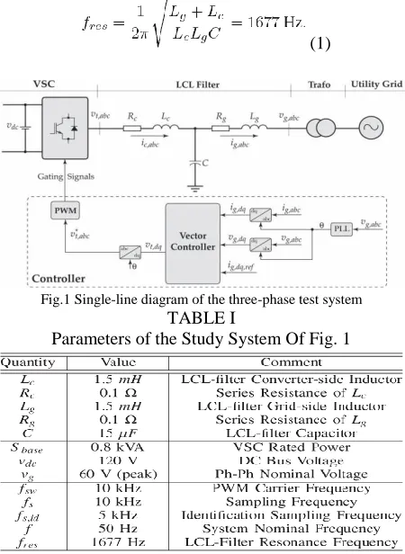
Fig. 1 shows the single-line diagram of the study system, which comprises a three-phase VSC, interfaced to the utility grid though an LCL-filter and a coupling transformer. The filter is composed of a grid-side inductor Lg, a capacitor C, and a VSC-side inductor Lc. The internal resistance of Lg and Lc are represented by Rg and Rc, respectively. The VSC DC-side is fed by a continuous voltage source, and therefore, its dynamics are neglected in this paper. Table I presents the parameters of the study system of Fig. 1. According to the parameters of Table I, the resonance frequency of the LCL-filter-based system is calculated as follows:
(1)
Fig.1 Single-line diagram of the three-phase test system
TABLE I
Parameters of the Study System Of Fig. 1
In the system of Fig.1, for synchronization, a phase-locked loop (PLL) is utilized, which extracts the phase-angle of the grid voltage and forces its q-component to zero. Therefore, to regulate the real and reactive power exchange, a vector control strategy is adopted that controls the d- and q-components of the grid current, which are proportional to the real and reactive power, respectively. Feeding the errors between the dq-components of the grid current and their respective reference values to the controller, the control signals, i.e., the dq-components of the PWM block input signals, vt, dq, are then generated. The vector controller is also in charge of damping the system around its resonance frequency. All inputs/outputs of the proposed control system are illustrated in the respective block diagram of Fig. 1.
III. VECTOR CONTROL STRATEGY
In this section, the design procedure of the damping vector control strategy for LCL-filter-based VSCs is detailed, which is based on a constrained optimization-based loop shaping method. It uses the MIMO nonparametric model of the system, i.e., G(jω), along with a linearly parameterized MIMO controller, i.e., K(z), to form an open-loop transfer function matrix, i.e., L(jω)=G(jω)K(jω)∀ω∈R. Based on the dynamic performance and the decoupling requirements, a desired open-loop transfer function matrix, i.e., LD(s), is also formed, and its diagonal and off diagonal elements are determined. Minimizing the second norm of the error between the open-loop transfer function matrix and the desired one, the coefficients of the controller are optimally determined. To ensure the stability and the required dynamic performance of the closed-loop system, the minimization problem is subject to constraints. The design procedure is divided into three main steps: (1) the determination of the required nonparametric model, (2) the determination of the class of the controller, and (3) solving the optimization problem and finding the optimal coefficients of the controller. In the following, the steps are detailed.
A. Nonparametric Model:
(2) To achieve the nonparametric model of the system of Fig. 1, exciting vt, d with a stimulus signal, e.g., pseudo random binary sequence (PRBS), the frequency response ofG11andG21 could be identified as
(3)
The same holds for obtaining G22 and G12 through the excitation of vt,q . It must be noted that the identification sampling frequency, i.e., fs,id, could be different from the control sampling frequency, i.e., fs, and in this paper, fs,id = 5kHz, which is compatible with the Shannon theorem.
B. Controller Class:
The vector control strategy is responsible for regulating the dq-components of the grid current through manipulating the dq-components of VSC terminal voltage, i.e., vt, dq. Therefore, to control such a system, a 2 ×2 controller is required. A generic form of such a multivariable discrete-time controller in the z-domain is given by
(4)
Where ed and eq are the current errors in the d- and q-axes, respectively. The structural diagram of the controller is depicted in Fig.2.
Fig.2 Structural diagram of the controller
Conventional vector control strategies for L-filter-based VSCs utilize PI-controllers as the elements of the controller matrix [2], [3]. In such systems, only one dominant pole exists in each axis, which could be
compensated by the zero of the utilized PI-controllers. In LCL-filter-based systems, however, this is no longer valid as more poles are introduced by the additional passive LC elements. Thus, if PI-controllers are used for the vector control of LCL-filter-based, all poles of the system may not be compensated, and therefore, damping strategies are required to attenuate the effects of the uncompensated poles. In this paper, high-order controllers are utilized as the elements of the controller in order to compensate for all poles of the LCL-filter-based system such that no extra damping strategies are required. Thus, each element of the controller matrix of (4) is a 5th-order controller in the z-domain. For example, K11is given by
(5) In which the vector ρ contains the controller matrix coefficients as follows:
(6)
Therefore, the open-loop transfer function matrix of the LC L filter-based system is given by
(7)
C. Optimization-Based Loop Shaping:
The loop shaping of the open-loop transfer function matrix, i.e., L, is carried out by minimizing the square second norm of the error between the individual entries of Land a desired open-loop transfer function matrix, LD(s). Consequently, the control design procedure turns into an optimization problem as follows
(8)
The desired open-loop transfer function matrix, LD, is chosen to meet the system requirements, e.g., satisfactory dynamic response and reduced coupling between the outputs, i.e., ig, d and ig, q. In this paper, the desired open-loop transfer function is selected as
In which ωc= 1200rad/s. Note that the bandwidth of the closed-loop system is manipulated by the choice of ωc. In order to ensure the stability and also the dynamic performance of the to-be-designed controller, the minimization problem is subject to several constraints. The reference proves that to shape the sensitivity function of the closed loop system, the minimization problem must be subject to the following linear constraints:
(10) whereW1 (jω) is a weighting filter. In this paper, W1 (jω) = 0.5, which guarantees a gain margin of at least 2 and a phase margin of greater than 29◦. Moreover, to ensure the stability of the closed-loop system, the minimization problem must satisfy the generalized Nyquist stability criterion. Therefore, as proved, the minimization problem must also satisfy the following constraints.
(11)
Where r1 (ω, ρ) and r2 (ω, ρ) are defined as
(12)
(13)
The optimization problem of (8) constrained to (10) and (11), known as a semi infinite problem (SIP), includes infinite number of constraints and finite number of variables. A practical solution to this problem is to neglect the frequencies above a certain frequency, i.e., ωmax, for which the gains of the elements of the open-loop transfer function matrix are close to zero. In discrete-time systems, the frequencies above the Nyquist frequency could be neglected.
Moreover, in order to have a finite number of frequency points, the gridded frequency interval [0 ωmax] could be taken, which contains finite frequency points. Therefore, the SIP problem turns into a semi definite problem (SDP) and could be solved utilizing standard SDP-solvers, e.g., SeDuMi.
Choosing N linearly spaced frequencies within the range of [0 ωmax] ∈ R, the quadratic objective function is approximated by
(14)
Therefore, the following optimization problem is deduced:
(15)
IV. PHOTOVOLTAIC SYSTEM
A photovoltaic system, also PV system or solar power system is a power system designed to supply usable solar power by means of photovoltaics. It consists of an arrangement of several components, including solar panels to absorb and convert sunlight into electricity, a solar inverter to change the electric current from DC to AC, as well as mounting, cabling and other electrical accessories to set up a working system. It may also use a solar tracking system to improve the system's overall performance and include an integrated battery solution, as prices for storage devices are expected to decline. Strictly speaking, a solar array only encompasses the ensemble of solar panels, the visible part of the PV system, and does not include all the other hardware, often summarized as balance of system (BOS). Moreover, PV systems convert light directly into electricity and shouldn't be confused with other technologies, such as concentrated solar power or solar thermal, used for heating and cooling.
Fig.3 Single diode model of a solar cell
V. DESIGN OF A FUZZY CONTROLLER
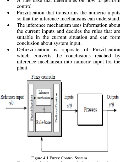
The Fuzzy control is a methodology to represent and implement a (smart) human’s knowledge about how to control a system. A fuzzy controller is shown in Figure.14. The fuzzy controller has several components:
A rule base that determines on how to perform control
Fuzzification that transforms the numeric inputs so that the inference mechanisms can understand. The inference mechanism uses information about the current inputs and decides the rules that are suitable in the current situation and can form conclusion about system input.
Defuzzification is opposite of Fuzzification which converts the conclusions reached by inference mechanism into numeric input for the plant.
Figure 4.1 Fuzzy Control System
Fuzzy logic is a form of logic that is the extension of boolean logic, which incorporates partial values of truth. Instead of sentences being "completely true" or "completely false," they are assigned a value that represents their degree of truth. In fuzzy systems, values
are indicated by a number (called a truth value) in the range from 0 to 1, where 0.0 represents absolute false and 1.0 represents absolute truth. Fuzzification is the generalization of any theory from discrete to continuous. Fuzzy logic is important to artificial intelligence because they allow computers to answer ‘to a certain degree’ as opposed to in one extreme or the other. In this sense, computers are allowed to think more 'human-like' since almost nothing in our perception is extreme, but is true only to a certain degree.
Table 1: IF-THEN rules for fuzzy inference system
The fuzzy rule base can be read as follows
IF e(t) is NB and ∆e(t) is NB THEN u(t) is NB IF e(t) is <negative big> and ∆e(t) is <negative big>THEN u(t) is <negative big>
VI. MATLAB RESULTS
Fig.6 Simulation response of the system of the reference change in the d-axis: (a) the three-phase grid voltage, (b) the three-phase grid current, (c) the three-phase converter current, and (d) the d-and q-components of the
grid current.
Fig.7 Simulation response of the system of the reference change in the q-axis: (a) the three-phase grid voltage, (b) the three-phase grid current, (c) the three- phase converter current, and (d) the d-and q-components of
the grid current.
Fig.8 Simulation response of the system of the reference change in the d-axis while the LCL-filter parameters contain uncertainties: (a) the
three-phase load voltage, (b) the three-three-phase grid current, (c) the three-three-phase converter current, and (d) the d-and q-components of the grid current.
Fig.9 Simulation response of the system of Fig. 1 to the reference change in the q-axis while the LCL-filter parameters contain uncertainties: (a) the three-phase grid voltage, (b) the three-phase grid
Fig.10 Simulation diagram of proposed PV system with Fuzzy controller
Fig.11 Simulation response of the proposed system with PV (a) the phase grid voltage, (b) the phase grid current, (c) the
three-phase converter current, and (d) the d- and q-components of the grid current.
Fig.12 PV Voltage and Three phase converter voltages
Fig.13 FFT analysis of Converter Current with PI controller
Fig.15 FFT analysis of Converter Current with Fuzzy controller
Fig.16 FFT analysis of Grid Current with Fuzzy controller
VII. CONCLUSION
This paper proposes a high order control strategy for grid connected VSC with LCL filters by using Fuel cell and PV cell is proposed in this paper. To damp the resonance phenomenon of the LCL-filter a MIMO controller matrix is adopted whose elements are linearly parameterized high-order controllers with integrators. Contrary to the existing vector control schemes for VSCs with LCL-filters and PV cell the proposed approach does not require extra damping methods. Moreover the dynamic performance of the proposed approach is similar to the existing ones while its axis-decoupling capability is superior. The design procedure of the proposed controller is based on loop shaping and has three main steps:
(1) Attaining a nonparametric model of the system (2) Determining the class of the to-be-designed controller. (3) Solving a constrained convex optimization problem.
The Fuzzy based three phase grid connected PV system has been proposed. The harmonics are eliminated by the LCL filter. The power extracted from the PV array increased by the fuzzy logic controller which develop the system performance in varying weather condition. The THD of the grid-current was 0.04% and converter current was 0.04%.
REFERNCES
[1] O. Senturk, L. Helle, S. Munk-Nielsen, P. Rodriguez, and R. Teodorescu, “Power capability investigation based on electro thermal models of press pack IGBT three-level NPC and ANPC VSCs for multi megawatt wind turbines,” IEEE Trans. Power Electron., vol. 27, no. 7, pp. 3195–3206,
Jul. 2012.
[2] B. Bahrani, A. Karimi, B. Rey, and A. Rufer, “Decoupled dq-current control of grid-tied voltage source converters using nonparametric models,” IEEE Trans. Ind. Electron., vol. 60, no. 4, pp. 1356–1366, Apr. 2013. [3] B. Bahrani, S. Kenzelmann, and A. Rufer, “Multivariable-PI-based dq current control of voltage source converters with superior axis decoupling capability,” IEEE Trans. Ind. Electron., vol. 58, no. 7, pp. 3016–3026, Jul. 2011.
[4] B. Bahrani, A. Rufer, S. Kenzelmann, and L. Lopes, “Vector control of single-phase voltage-source converters based on fictive-axis emulation,” IEEE Trans. Ind. Appl., vol. 47, no. 2, pp. 831–840, Mar./Apr. 2011.
[5] M. Liserre, R. Teodorescu, and F. Blaabjerg, “Stability of photovoltaic and wind turbine grid-connected inverters for a large set of grid impedance values,” IEEE Trans. Power Electron., vol. 21, no. 1, pp. 263–272, Jan. 2006.
[6] P. Sun, C. Liu, J.-S. Lai, and C.-L. Chen, “Grid-tie control of cascade dual buck inverter with wide-range power flow capability for renewable energy applications,” IEEE Trans. Power Electron., vol. 27, no. 4, pp. 1839– 1849, Apr. 2012.
[7] R. Teodorescu, M. Liserre, and P. Rodriguez, Grid Converters for Photovoltaic and Wind Power Systems. Hoboken, NJ, USA: Wiley, 2011.
[8] H. Akagi and R. Kondo, “A transformerless hybrid active filter using a three-level Pulse width Modulation (PWM) converter for a medium voltage motor drive,” IEEE Trans. Power Electron., vol. 25, no. 6, pp. 1365– 1374, Jun. 2010.
vector control of biaxial excitation generator/motor for automobiles,” IEEE Trans. Ind. Appl., vol. 47, no. 2, pp. 812–819, Mar./Apr. 2011.
[10] J. Chivite-Zabalza, M. Rodriguez Vidal, P. Izurza-Moreno, G. Calvo, and D. Madariaga, “A large power, low-switching-frequency voltage source converter for FACTS applications with low effects on the transmission line,” IEEE Trans. Power Electron., vol. 27, no. 12, pp. 4868–4879, Dec. 2012.
[11] G. Kalcon, G. Adam, O. Anaya-Lara, S. Lo, and K. Uhlen, “Small-signal stability analysis of multi-terminal VSC-based DC transmission systems,” IEEE Trans. Power Syst., vol. 27, no. 4, pp. 1818–1830, Nov. 2012. [12] R. Teodorescu, F. Blaabjerg, M. Liserre, and P. Loh, “Proportional resonant controllers and filters for grid-connected voltage-source converters,” Proc. Inst. Elect. Eng.––Elect. Power Appl., vol. 153, no. 5, pp. 750–762, Sep. 2006.
[13] V. Blasko and V. Kaura, “A novel control to actively damp resonance in input LC filter of a three-phase voltage source converter,” IEEE Trans. Ind. Appl., vol. 33, no. 2, pp. 542–550, Mar./Apr. 1997.
[14] J. Dannehl, C. Wessels, and F. Fuchs, “Limitations of voltage-oriented PI current control of grid-connected PWM rectifiers with LCL filters,” IEEE Trans. Ind. Electron., vol. 56, no. 2, pp. 380–388, Feb. 2009.
[15] R. Pea-Alzola, M. Liserre, F. Blaabjerg, R. Sebastian, J. Dannehl, and F. W. Fuchs, “Analysis of the passive damping losses in LCL-filter-based grid converters,” IEEE Trans. Power Electron., vol. 28, no. 6, pp. 2642– 2646, Jun. 2013.