1
ON THE PERFORMANCE OF IMT-2000 COMMUNICATION LINK
BASED ON STRATOSPHERIC PLATFORMS
Iskandar, Shigeru Shimamoto
Graduate School of Global Information and Telecommunication Studies, Waseda University 1011 Okuboyama Nishi-Tomida Honjo-shi Saitama 367-0035 Japan
E-mail: [email protected]
Abstract
A new means for providing wireless communication has been currently proposed. It is based on aerial vehicle known as High Altitude Platform or Stratospheric Platforms (SPF). The SPF will be operated at an altitude of 17-22 km above the ground. Therefore, the channel condition may be different compared with those of the conventional terrestrial or satellite wireless channel. In this paper, the channel propagation characteristic of such a system is firstly investigated by means of ray tracing algorithm. We emphasize our investigation in a typical urban environment, in which the mobile users mostly exist. We developed building block model for simulation based on building height distribution, which is obtained from measurement inside Tokyo. As a result, propagation loss model and Ricean channel parameter for the SPF channel is reported in different scenarios. By using this result we then estimate the required transmitted power of SPF to serve the mobile users in a several transmission rate that is used in IMT-2000 services. Finally, an evaluation of BER of IMT-2000 link is performed in order to estimate the system level performance. From this evaluation, the main contribution of this paper is to clearly show the critical limitations of both power requirement as well as system level performance of mobile communication IMT-2000 by using the concept of the SPF.
Keywords: link performance, IMT-2000, high altitude platform, stratospheric platform
1. Introduction
The increasing demand of high-capacity wireless services has led the rapid deployment of wireless communication infrastructure, especially for delivery at remote area. Currently, we have two well-established methods for providing wireless services those are terrestrial and satellite systems. In terrestrial system, a huge number of base stations have to be deployed for the need of line of sight propagation path. While in satellite system the problem is capacity limitation. In recent year, another alternative has been attracting much the attention of providing wireless services. It is based on an unmanned or manned airship or aircraft that is called High Altitude Platform Station (HAPS) or known by different names as Stratospheric Platform (SPF) [1-4]. They will be located at stratosphere in the altitude of around 17-22 km above the ground. This altitude has not been used for telecommunication services except perhaps for the use related to scientific re-search. Air stream in this altitude is relatively calm and therefore it is a fairly niche area to put the communication facilities onboard the platform.
SPF has the capability to combine the best features of the conventional terrestrial and satellite system. For example, a wider coverage area compared with the terrestrial system but lower power requirement and propagation delay compared with the satellite system. The most important advantages of SPF systems are their easy and incremental deployment, flexible and reconfigurable, low-cost operation, high elevation angles, broad coverage, broadband capability, ability to move around in emergency situation, etc. With those excellent features of SPF, ITU has allocated spectrum to this system in a several frequency band. Those are in the bands of 48/47 GHz world wide, 31/28 GHz for the use mostly in Asia country, and bands of 2 GHz for the use of 3G and beyond 3G.
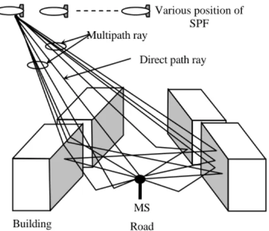
Figure 1. SPF Configuration for IMT-2000 Figure 2. Multipath in a SPF channel
taken an initiative and responsibility of a national R&D SPF project since 1998 [6]. The similar ongoing project has also been undertaken in the European countries through the CAPANINA project [7], in the U.S. they have the Aerovironment/Sky-Tower project [8], and also the stratospheric platforms program in Korea with KARI/ETRI [9-10]. Those investigations are indeed devoted to put the SPF into operation for the new wireless infrastructure.
The most promising applications that can be carried out by the SPF system are cellular telephony, broadband local multipoint distribution system (LMDS) services, and access provision to digital networks (internet, ISDN). From the geometrical features of the system, SPF is designed to have the capability to deliver high quality digital video, TV broadcasting, as well as a remote sensing and navigation system.
The basic cellular configuration of SPF for IMT-2000 is depicted in Figure 1. A single platform is able to cover a large area within a radius of 50-200 km, depending upon the minimum elevation angle and frequency. Furthermore, inter platform optical link provides a gigabit data rate transmission. Therefore, multiple platforms can be arranged in the sky in order to increase the capacity or to extend the coverage area. As a result, all wireless communication toward the end users can be realized by this system without installing many base stations. This appealing system is therefore expected to be the new wireless infrastructure in the near future.
As the work was progressing in development of such a system, one aspect that has not been much investigated is propagation characteristics of its link. We know that the propagation characteristic in SPF mobile communication system is a complicated process that involves multiple reflections, diffraction, or scattering. The simplified model of propagation mechanism can be depicted such as in Figure 2. Specific research to the
small scale propagation modeling for SPF channel is introduced in [11]. However the model doesn’t analyze the impact of elevation and azimuth angle, in which the SPF is seen by the mobile station (MS). In our previous work, we have performed the performance evaluation and the channel characteri-zation for SPF system based upon the measurement with considering the impact of elevation angle [12,13]. We found that the platform channel is Ricean distributed and the performance of the channel is an increasing function to the elevation angle. On the other hand, the SPF is a power limited system. Thus, while the platform is now being developed, an estimation to the required transmitted power onboard the platform is considered as a matter of urgency. Therefore, in this paper, a ray tracing based propagation loss model, power requirement estimation, and system level performance evaluation of communica-tion link are demonstrated in order to estimate the possibility of using SPF for IMT-2000 services.
2. Method of Experiment
In case of SPF with high elevation angle, propagation path is mostly characterized as having line of sight (LOS). In this case, many number of SPF are required to cover global coverage. By contrary, when SPF is deployed with low elevation angle to extend the coverage for example, propagation path will suffer from non-line of sight (NLOS) situation. It then results the increasing propaga-tion loss especially for the user located near the edge of the coverage. To show the propagation environment of SPF communication link, an extensive series of field experiments are performed inside and nearby the city of Tokyo, Japan. The model configuration of our experiment is depicted in Figure 3 and Figure 4 for side view and top view, respectively.
The experiments have two main targets. First target is to find the average building height and the result is demonstrated in Table 1. In the table, we observed that Coverage
Minimum elevation angle
SPF Inter-platform
link
Cell
Direct path ray Multipath ray
MS Building
Various position of SPF
Figure 3. Side view (elevation angle variation) Figure 4. Top view (azimuth angle variation)
Table 1. Average building height and density
Area Average building
height [m]
Building density
[pieces/km2]
Shinjuku 25.5 290
Shibuya 25.0 200
Asakusa 22.1 580
Kiryu 19.1 7
in Shinjuku, an average building height is found to be the highest and followed by that in Shibuya, Asakusa, and Kiryu. In the table, we also observed building
density in pieces/km2. We found the highest building
density is in Asakusa and followed by that in Shinjuku, Shibuya, and Kiryu. From this geographical data, we then develop the model of urban environment for propagation evaluation that will be presented in the next section of this paper.
The second target of our survey is to estimate visibility. The visibility is defined as the probability at each elevation angle that the MS looking at the SPF without shadowed by the building. The experiment is carried out by driving a car which is equipped with a video camera. Our car was moved the various directions in the city for about 5 km in total. As we know that the propagation attenuation will increase when the link is shadowed by the building or structure. We performed in the survey
four different azimuth angles (i.e. 0º, 30º, 60º, and 90º)
while elevation angle is measured from 10º to 80º in a
step of 10º. Elevation angle is defined as in Figure 3
while azimuth angle is a relative angle with respect to the street direction such as described in Figure 4. Result of visibility in Asakusa area is demonstrated in Figure 5.
The markers (triangles, diamonds, squares, and circles) demonstrate the result of experiments, and the lines (solid, dashed, dotted, and dashed-dot) illustrate an approximation of the visibility derived by mathematical expression. Mathematical empirical model for visibility for the data of Asakusa area can be expressed as a
function of elevation (α) and azimuth (θ) angle by the
following equation
⎪⎩ ⎪ ⎨ ⎧
= = =
0 0 0 sin
0 01
. 0
90 , 60 , 30 ; ) (sin
0 ; ) (sin ) , (
θ α
θ α
θ α
θ v
p (1)
where θ =0º is in a positive y-axis direction and θ =90º
is in a negative x-axis direction as explained in Figure 6. Bold solid line in Figure 5 is a theoretical Rayleigh distribution model for the visibility. We found from our
survey, the visibility curve of azimuth 30º, 60º, and 90º
have a good agreement with the Rayleigh curve. It means that the visibility for those azimuth angles can be modeled by Rayleigh distribution.
We developed building block model that represents an urban environment for propagation evaluation. It then followed by examination of ray tracing algorithm,
00 300
600
900
00 100
200 300
400 500
600
700 80
10 20 30 40 50 60 70 80 0 0.1 0.2 0.3 0.4 0.5 0.6 0.7 0.8 0.9 1
Elevatio n angle [deg]
Vis
ibil
it
y
Az imuth 0 [deg], Equation (1) Az imuth 30 [deg], Equation (1) Az imuth 60 [deg], Equation (1) Az imuth 90 [deg], Equation (1) Az imuth 0 [deg], M easurement Az imuth 30 [deg], M easurement Az imuth 60 [deg], M easurement Az imuth 90 [deg], M easurement Ray leigh
Figure 5. Visibility in Asakusa Figure 6. Top view of the model
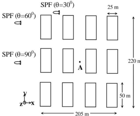
which is applied to the developed building block model for simulation. Building block model we developed in this paper is an approaching model to the result of our experiments. We developed the model for the block of
12 buildings over the area of 0.0451 km2 (205 m x 220
m) and is depicted in Figure 6. It means the building
density of our model is 266 pieces/km2. For a
simplification of using ray tracing algorithm, we assume all the buildings under test have equal height of 20 m. Therefore, if we refer to the result of experiment, our building block model is a representation of urban environment characteristic between Asakusa and Kiryu area in the sense of average building height. These areas have a characteristic with a high-rise building representing one of the most metropolitan cities.
In the model, the SPF elevation angle is made to vary
from 5º to 90º to provide a complete model of
propagation evaluation for this system. Meanwhile, three scenarios of the SPF position that is seen by the
MS are considered. Those are azimuth angle (θ ) of 90º,
60º and 30º in order to observe different direction of
propagation path between the SPF and the MS. The MS is positioned in the center of the street (point A) assuming the user is in a vehicle in the road. Table 2 is a summary of geometrical parameters involved in the ray tracing simulation.
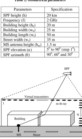
Ray tracing tool we developed follows an approach model proposed by Tila [14]. But in our model, we included diffraction mechanism effects from building rooftops. This mechanism occurs when a large object such as a building obstructs the radio path, causing the waves to be bended into shadow region and continue to propagate toward the receiver. It is therefore found to be
important to include diffraction in ray tracing algorithm, especially in case of SPF with low elevation angle. The model employs a number of virtual transmitters as depicted in Figure 7. They are located around the area under test in order to overcome the difficulty of applying the ray launching methods for the large separation such as from the SPF to the MS. The generation of virtual transmitters is repeated when the elevation angle has to be changed in the simulation. Note in this paper we examined various elevation angles from 5º to 90º.
We employ nine categories of ray to be included in our simulation. These ray categories are line of sight, single reflection from building, single reflection from street, double reflection from building to street, double reflection from building to building, diffraction from rooftop of building, diffraction from rooftop and single reflection from building, diffraction from rooftop and single reflection from street, and diffraction from rooftop and double reflection from building to street. Rays outside the above categories are assumed to leave the target and terminated from the simulation environment.
We assume the following electrical parameters throughout the prediction in this paper. Buildings are
assumed to be made of concrete with εr = 3 and σ =
0.005 Ω-1m-1, while the ground is modeled as having εr
= 15 and σ = 7 Ω-1m-1 [15], where εr and σ are dielectric
constant and conductivity, respect ively. In the prediction, two situations were observed, those are LOS situation and shadow situation (when direct ray is obstructed by the building nearby the MS).
x
y
z SPF (θ=600)
SPF (θ=900)
SPF (θ=300)
A
205 m
220 m
Table 2. Geometrical parameters
Parameters Specification
SPF height (h) 20 km
Frequency (f) 2 GHz
Building height (hb) 20 m
Building width (wb) 25 m
Building length (wl) 50 m
Street width (ws) 35 m
MS antenna height (hm) 1.5 m
SPF elevation (α) 50 to 900 (step 10)
SPF azimuth (θ) 900, 600 and 300
Figure 7. Concept of virtual transmitters [14]
Ray tracing algorithm requires firstly searching rays and secondly computing electromagnetic field of each ray. The basic idea in ray tracing is to employ a geometrical optic (GO) and uniform theory of diffraction (UTD). UTD is an extension method of GO to include diffraction [16].
Basic principle of GO is a Snellius’s law of reflection as depicted in Figure 8. By using ray tracing algorithm, we are able to search the reflection rays until they reach the receiver. In this work we consider up to two reflections either by the building surface, the street or their combination. Diffraction principle as described in Figure 9 is applied in our simulation. Rays undergo diffraction by rooftop edge of the building and continue up to two reflections are also considered in the simulation.
Both transmitting (SPF) and receiving (MS) antennas are assumed to be an isotropic with a 0 dB gain. Therefore, an electric fields of ray arriving at the
receiving antenna for direct ray (ELOS), reflected ray (ER)
and diffracted ray (ED), respectively are calculated using
the following formulas
0 0
0
d e E E
d j
LOS
β −
= (2)
2 1
) ( 0
2 1
s s e R E E
s s j
R = ⋅ +
+ − β
(3)
) ( 3 3
0 3
) ( '
s s j
D s s s e
s D s E
E − +
+ ⋅
= β (4)
where β=λ/2π is propagation constant, E0 is emitted
electric field from transmitter, d0 is direct path length, s1
is path length from the source to reflection point, s2 is
path length from reflection point to the receiver, s is
path length from the source to diffraction point, and s3 is
path length from diffraction point to receiver. R is a
Fresnel dyadic reflection coefficient and D is dyadic
finite conductivity edge diffraction coefficient. These two coefficients follow the general formulation
SPF
N Building
Street MS
Virtual transmitters
Figure 8. Reflection mechanism Figure 9. Diffraction mechanism
presented by Bertoni [15]. Finally, respective rays for each ray category were added at the MS and expressed as
∑
= = n
j j
i E
E 1
(5)
Ej is the received electric field of the j-th ray for ith
category. Note we assume that the ray tracing algorithm employed in this work consider up to nine categories of ray as mentioned above. Although the precision can be improved by additional ray category such as double diffraction in combination with multiple reflection from wall and street, however we have to compensate by computational complexity and therefore it actually time consuming. Generally, rays after second reflection will have very weak power. In this work, the total electric field contribution consists of vector summation of nine ray categories and can be expressed by
∑
= = 9 1i i
Tot E
E (6)
Finally, the total path loss (L) can be given by
⎟ ⎟ ⎠ ⎞ ⎜
⎜ ⎝ ⎛ =
0
4 log 20
E E
L Tot
π
λ
(7)From equation (7), now we are able to demonstrate the propagation path loss for the above-mentioned model as a function of elevation and azimuth angle, which is presented in the following section.
3. Result and Discussion
Figure 10 exhibits the ray-tracing simulation result of a total propagation loss obtained from the calculation of a direct LOS ray and multipath scattered rays. In a figure,
we can see the propagation loss in a LOS situation for
three kinds of azimuth angle (90º, 60º, and 30º ) are
exactly similar along with elevation angle variation. However in a NLOS situation, different azimuth angle exhibits different value of propagation loss. This is due to the contribution of the rays is different for different
azimuth angle. In azimuth angle of 90º, the propagation
loss shows to be the largest and decreases as azimuth angle also decreases. We observe in NLOS situation, the propagation loss dramatically increases by the order of 20 dB or more compared to that in LOS region. In this case we can evaluate that the propagation loss in the SPF communication is less sensitive concerning to the azimuth angle in case of high elevation angle. By contrary, in low elevation angle or particularly in the shadow region, the propagation loss is dependent and quite sensitive to the azimuth angle.
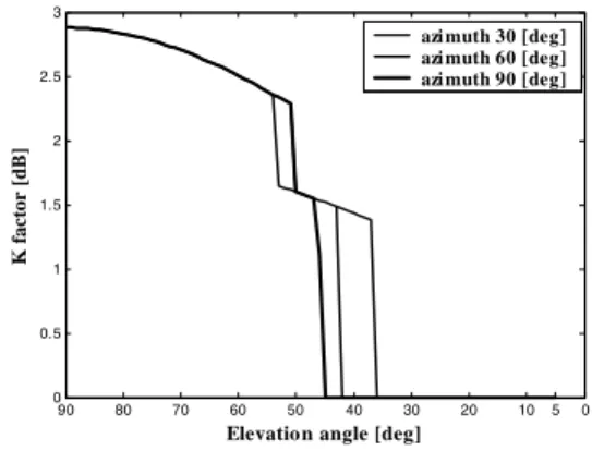
We are also able to obtain K factor from our ray tracing
simulation result. The K factor is a Ricean distribution
parameter that indicates the ratio between a direct ray power and the multipath power. In this paper, we
directly get the K factor value by using the following
expression
2 2
2σ
A
K =
(8)
where A represents the amplitude of direct LOS ray or
dominant rayand σ2 is the variance or average power of
the multipath components. Since there is no direct ray in
NLOS region, K factor goes to zero in this region, for
example in low elevation angle. It is shown in Figure 11, there is a transition region between LOS and NLOS
region (ranging from 36º up to 46º of elevation angle for
all azimuth angle), K factor is gradually increased due to
the presence of direct ray. From these results, it is obvious that the MS may be fail to establish the communication link with the SPF either due to a very
Receiver γ
φ
Rooftop edge of building Source
θ θ
Source
Reflection wave
Image
0 5 10 20 30 40 50 60 70 80 90 0 0.5 1 1.5 2 2.5 3
Elevatio n angle [deg]
K fa
ct
o
r [d
B]
azi muth 30 [deg] azi muth 60 [deg] azi muth 90 [deg]
Figure 10. Predicted propagation loss for the model shown in Figure 6
Figure 11. K factor
Table 3. IMT-2000 specifications for SPF [19]
Item Specification
Frequency [GHz] 2
Bit rate [kbps] 8, 32, 64, 384, and 2000
SPF antenna gain [dBi] 30
MS antenna gain [dBi] 0
Boltzmann’s constant [J/K] 1.38x10⁻²³
Temperature’s chamber [K] 290
Link margin [dB] 15.4
Cable, connector, and other losses [dB] 2
Eb/N0 [dB] Max. 7.9
high propagation loss or very poor condition of the
channel performance indicated by a very low value of K
factor
One of the proposed services in SPF communication is the next generation of mobile communication IMT-2000 [17]. In this paper, we present an analysis of required transmit power for such a system. For digital CDMA-based such as IMT-2000, the required bit energy per
noise power spectral density (Eb/N0) can be expressed
by the following simple formulation [18]
L b T T T b M L L T k R G G P N E 0 0
0 (
α
,θ
)= (9)
PT : SPF power transmit
GT : SPF antenna gain
GT : MS antenna gain
Rb : Bit rate
k : Boltzmann’s constant (1.38×10⁻²³ m2kgs-2K-1)
T0 : Receiver temperature
L(α,θ): Propagation loss obtained in Fig. 10
L0 : Cable, connector, and combiner loss
ML : Link margin
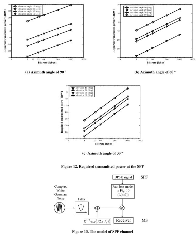
We employ the standard specifications that are used for IMT-2000 services, which are described in Table 3 in order to estimate the required transmit power by the SPF. The purpose of this estimation is to observe the capability of SPF, which is regarded as a power limited system in order to deliver mobile services to the users. Propagation simulation result in Figure 10 therefore needs to be used to achieve this goal. Since IMT-2000 provides various applications (i.e. voice, data, multimedia, and internet), it is important to consider bit rate in the evaluation of required transmit power.
Results are shown in Figure 12 (a), (b) and (c) for the
scenarios of azimuth 90º, 60º and 30º, respectively. A
very critical required transmit power occurs at elevation
angle below 10º in a scenario azimuth angle of 90º, even
for a very low information rate (8 kbps). For that case, the required transmit power would vary between 31.2 W (8 kbps) and 7.80 kW (2 Mbps) for a single carrier. Such high values may be impractical. However, for
elevation angle greater than 10º, the required transmit
power for low to medium information rate (i.e. 8 kbps up to 384 kbps) is fairly low so that the SPF system is possible to deliver IMT-2000 services in all azimuth angle scenarios. In a LOS region such as elevation angle
greater than 60º, in the sense of power requirement, the.
0 5 10 20 30 40 50 60 70 80 90 -200 -190 -180 -170 -160 -150 -140 -130 -120 -110 -100
Elevation angle [deg]
Pr
opagation Loss
[-dB]
Azi muth 90 [deg] Azi muth 60 [deg]
Azi muth 30 [deg] LOS NLOS 0 5 10 20 30 40 50 60 70 80 90 -200 -190 -180 -170 -160 -150 -140 -130 -120 -110 -100
Elevation angle [deg]
Pr
opagation Loss
[-dB]
Azi muth 90 [deg] Azi muth 60 [deg]
Azi muth 30 [deg] LOS
1 8 16 32 64 384 2000 10000 -40
-30 -20 -10 0 10 20 30 40
Bit rate [kbps]
Re
q
u
ir
ed
tr
ans
m
itte
d powe
r [
d
B
W
]
elevation angle 10 [deg] elevation angle 20 [deg] elevation angle 30 [deg] elevation angle 60 [deg]
1 8 32 64 384 2000 10000 -40
-30 -20 -10 0 10 20
Bit rate [kbps]
Re
q
u
ir
ed
tr
ans
m
itte
d powe
r [
d
B
W
] elevation angle 10 [deg]elevation angle 20 [deg] elevation angle 30 [deg] elevation angle 60 [deg]
(a) Azimuth angle of 90 º (b) Azimuth angle of 60 º
1 8 32 64 384 2000 10000 -40
-35 -30 -25 -20 -15 -10 -5 0
Bit rate [kbps]
Req
u
ired transmitt
ed po
w
e [
d
B
W
]
elevation 10 [deg] elevation 20 [deg] elevation 30 [deg] elevation 60 [deg]
(c) Azimuth angle of 30 º
Figure 12. Required transmitted power at the SPF
Figure 13. The model of SPF channel
SPF is convinced to have the capability of delivering IMT-2000 services for bit rate up to 2 Mbps
We have analyzed the propagation loss and the required transmit power, however, in order to provide a complete evaluation we have to observe the BER performance of IMT-2000 link served by the SPF. Based on previous
analysis of K factor, it is shown that the channel of SPF
is characterized with two types of distribution. Those
are Ricean distributed for LOS situation and Rayleigh
distributed (K equals 0) for NLOS situation.
Considering those channel distribution at an appropriate
elevation angle (indicated by K factor in Figure 11), we
then evaluate BER performance. The model for BER simulation is shown in Figure 13. We employ DPSK modulation scheme and frequency slow and flat channel model in the evaluation. The latter assumption is based on a consideration that the coherence time of the Filter
{j f t}
K1/2exp 2π d Receiver
DPSK signal SPF
MS Path loss model
in Fig. 10 (L(α,θ)) Complex
White Gaussian
channel is larger than the symbol period and the coherence bandwidth of the channel is greater than the bandwidth of the signal. Although the delay profile of a real measurement result for a case of SPF is unavailable so far, the model proposed by Dovis et. al. [11] shows a good approach to the SPF channel. For DPSK modulation scheme under such fading channel condition, the closed form solution of bit error probability can be expressed by [18],
⎟ ⎠ ⎞ ⎜
⎝ ⎛
+ + − +
+ + =
K K K
K
PeDPSK
1 exp ) 1 ( 2
) 1 (
, Γ
Γ
Γ (10)
where 0
2 /N Eb
β
=
Γ is the average value of the signal to
noise ratio, β2
is unit variance of amplitude values of
the fading channel, and K is the Rice factor.
In Figure 14, we demonstrate average BER evaluation
result for azimuth angle of 90º, 60º and 30º. The bit rate
carried out by IMT-2000 is considered up to 2 Mbps. From the result, we can see that the link performance in
90º azimuth angle is the worst case, while in 30º azimuth
angle is the best case. In 90º of azimuth angle, the
performance decreases quickly when the link is NLOS. We also observed the performance in low elevation
angle such as lower than 30º, to achieve BER equals or
lower than 10-3; it is only possible if the bit rate is lower
than 384 kbps for all azimuth angles. On the other hand, in LOS situation such as in elevation angle greater than
45º, it is shown an error floor in the BER curves due to
the presence of multipath components. Therefore, SPF link would require multipath mitigation techniques to improve link quality.
4. Conclusion
This paper has presented and demonstrated the ray tracing algorithm to examine the performance of IMT-2000 communication link that is carried out by a new wireless media that is called the SPF. Specific model of urban environment was first developed based on the measurement data that was carried out inside and around Tokyo city for examination. Results of examination have clearly shown the channel model of the SPF mobile link. Two parameters were obtained
0 5 10 20 30 40 50 60 70 80 90 10-7 10-6 10-5 10-4 10-3 10-2 10-1 100
Elevation angle [deg]
Aver
age
BER
Rb = 8 kbps Rb = 32 kbps Rb = 64 kbps Rb = 384 kbps Rb = 2 Mbps
0 5 10 20 30 40 50 60 70 80 90 10-7 10-6 10-5 10-4 10-3 10-2 10-1 100
Elevation angle [deg]
Ave
ra
g
e BER
Rb = 8 kbps Rb = 32 kbps Rb = 64 kbps Rb = 384 kbps Rb = 2 Mbps
(a) Azimuth angle of 90 º (b) Azimuth angle of 60 º
0 5 10 20 30 40 50 60 70 80 90 10-7 10-6 10-5 10-4 10-3 10-2 10-1
Elevation angle [deg]
A
v
er
age
BE
R
Rb = 8 kbps Rb = 32 kbps Rb = 64 kbps Rb = 384 kbps Rb = 2 Mbps
(c) Azimuth angle of 30 º
from simulation. Those are propagation loss and Rice factor for different azimuth angle in a wide range of elevation angle. We found in general, propagation loss is a decreasing function of elevation angle. However, when elevation angle is decreasing, shadowing from building has led the propagation loss to dramatically increase by a value of 20 dB or more. Azimuth angles have also important contribution especially in the region
of low elevation angle. For azimuth 90º, the critical
required transmit power in the model is observed for
elevation angle below 20º. Such required power may be
too high in the implementation of SPF mobile communication. Finally, we demonstrate the BER performance for SPF IMT-2000 mobile link. Generally, the SPF link performance gets worse in low elevation angle. However, link performance is also influenced by azimuth angle. It means the orientation of the user toward the SPF is also important. The performance is intolerable even in the lowest bit rate of IMT-2000
services (8 kbps) when a user is in the position of 90º of
azimuth and elevation lower than 20º. It is because the
shadowing attenuation due to building was too high. Therefore, the critical limitation of choosing the minimum elevation angle in the application of IMT-2000 based on SPF has been clearly shown in this paper.
References
[1] G.M. Djuknic, J. Freidenfelds, Y. Okunev, IEEE
Commun. Mag. 35 (1997) 128.
[2] Y. Hase, R. Miura, S. Ohmori, Proceeding of 48th IEEE VTC Spring 2 (1998) 1191.
[3] S. Ohmori, Y. Yamao, N. Nakajima, IEEE
Commun. Mag. 38 (2000) 134.
[4] J. Thornton, D. Grace, C. Spillard, T. Konefal, T.C. Tozer, IEE Elec. and Commun. Eng. J. 13 (2001) 138.
[5] R. Miura, M. Oodo, Journal of Commun. Research Lab. 48 (2001) 33.
[6] R. Miura, M. Oodo, National Institute of Information and Communications Technology, http://www2.nict.go.jp/mt/b181/english/link-e.html [7] Stratospheric Platform Broadband Partners Project,
http://www.capanina.org/
[8] http://www.skytowerglobal.com/begin.html [9] http://www.kari.re.kr/
[10] http://www.etri.re.kr/
[11] F. Dovis, R. Fantini, M. Mondin, P. Savi, IEEE Journal on Select. Areas in Commun. 20 (2002) 641. [12] S. Shimamoto, T. Mikoshiba, S. Takakusagi, M. Hayashi, H. Shiba, IEICE Trans. Commun. E81-B, (1998) 2343
[13] Iskandar, S. Shimamoto, IEICE Trans. Commun. E89-B (2006) 937.
[14] F. Tila, P.R. Shepherd, S.R. Pennock, Proceeding of 11th IEE Antennas and Propagation Conference 1 (2001) 203.
[15] H.L. Bertoni, Radio Propagation for Modern Wireless Systems, Prentice-Hall PTR, New Jersey, 2000, Ch..3 & 5.
[16] Andrew S. Glassner, An Introduction to Ray Tracing, Morgan Kaufmann Publishers Inc., San Fransisco, 1989.
[17] ITU-R Resolution 221, “Use of high altitude platform stations providing IMT-2000 in the bands 1,885-1,980 MHz, 2,010-2,025 MHz in Region 1 and 3 and 1,885-1,980 MHz and 2,110-2,160 MHz in Region 2,” 2000.
[18] John G. Proakis, Digital Communications, 4th Ed. McGraw Hill, New York, 2000.
![Table 1. Average building height and density Area Average building height [m] Building density [pieces/km 2 ] Shinjuku 25.5 290 Shibuya 25.0 200 Asakusa 22.1 580 Kiryu 19.1 7](https://thumb-us.123doks.com/thumbv2/123dok_us/8077710.2140026/3.918.124.779.143.439/average-building-average-building-building-shinjuku-shibuya-asakusa.webp)