Installation and Programming Manual
Installation and Programming Manual
CE Declaration of Conformity
Hereby, RISCO Group declares that this control panel (ProSYS 128, ProSYS 40, ProSYS 16), with wired accessories (including cables) and wireless accessories, is in compliance with the essential requirements and other relevant provisions of Directive 1999/5/EC.
For the CE Declaration of Conformity please refer to our website: www.riscogroup.com.
Compliance Statement
Hereby, RISCO Group declares that the ProSYS series of control panels and accessories are suitable for use in systems designed to comply with PD6662:2004 Security Grade 3, Environmental Class II. (Security Grade 2 when using Wireless accessories).
The ProSYS series of control panels and accessories comply with the relevant parts of the EN50131 series of standards.
Table of Contents
CHAPTER 1: INTRODUCING PROSYS... 1-1 WHAT IS PROSYS?... 1-1 INSTALLING PROSYS ... 1-2 ABOUT WIRE... 1-2 PROSYSARCHITECTURE AND CAPABILITIES... 1-5 PROSYSFEATURES... 1-6 Feature-Specific Limitations ... 1-6 Main Panel ... 1-7 Zone Expansion ... 1-7 Wireless Devices... 1-7 Partitions/Areas... 1-8 Groups ... 1-8 Keypads ... 1-8 User Codes and Authority Levels... 1-9 Programmable Utility Outputs ... 1-9 Communication ... 1-9 Advanced Digital Voice Module... 1-10 Power Supply Expansion Module... 1-10 Access Control Expansion Module... 1-10 Scheduling ... 1-10 Event Logging ... 1-11 Printer Module... 1-11 Advanced Installation Tools ... 1-11 False Alarm Reduction... 1-11
CHAPTER 2: MOUNTING AND WIRING THE MAIN PANEL ... 2-1 STEP 1:MOUNTING THE MAIN PANEL... 2-1
Safety Precautions ... 2-2 What Makes a Good Ground?... 2-2
STEP 2:WIRING THE MAIN PANEL... 2-3
Wiring the Main Panel ... 2-3 Wiring the Zones to Sensors and Detectors (Zone Terminals Z1 through Z8)... 2-4 Wiring the Auxiliary Devices... 2-6 Wiring the Bell Sounders... 2-7 Wiring the Bell Tamper... 2-7 Wiring the Box Tamper ... 2-8 Wiring External Triggerable Devices ... 2-8 Connecting the J10 Connector... 2-9 Connecting to Ground (Earth) ... 2-10 Connecting Telephone Lines... 2-10 Jumper Settings ... 2-11 Connectors... 2-12 Connecting AC Power... 2-12
CHAPTER 3: INSTALLING EXTERNAL MODULES AND DEVICES ... 3-1 STEP 3:IDENTIFYING AND WIRING KEYPADS AND EXPANSION MODULES... 3-1
Programming Device ID Numbers... 3-1 Installing a Keypad... 3-2
STEP 4:ADDING MODULES... 3-3
Wiring Zone Expansion Modules... 3-3 Wiring Utility Output Modules ... 3-4 Wiring Power Supply Expansion Modules... 3-6
Wiring Additional Modules ... 3-7
STEP 5:APPLYING POWER... 3-7 CHAPTER 4: PROGRAMMING THE PROSYS... 4-1
USING THE PROSYSMAIN PANEL PROGRAMMING OPTIONS... 4-1 USING THE LCDKEYPAD... 4-2 PROGRAMMING FROM THE LCDKEYPAD... 4-4
Accessing the Installer Programming Menu... 4-4 Restoring Manufacturer's Programming Defaults... 4-6 Keypad Timeout... 4-8
CHAPTER 5: USING THE INSTALLER PROGRAMMING MENUS... 5-1 INSTALLER PROGRAMMING MENU CONVENTIONS... 5-1 SYSTEM... 5-2
System: Time Define... 5-2 System: System Control ... 5-5 System: Set Clock... 5-12 System: Windowing ... 5-13 System: System Labels ... 5-13 System: Tamper Sound ... 5-15 System: Default Enable/Disable... 5-16 System: Service Information ... 5-16 System: System Version... 5-17
ZONES... 5-18
Zones: One by One... 5-18 Zones: Partitions... 5-20 Zones: Zone Type... 5-21 Zones: Zone Sound ... 5-25 Zones: Termination ... 5-26 Zones: Loop Response... 5-28 Zones: Cross Zones... 5-29 Zones: Labels ... 5-31 Zones: Maintenance ... 5-31 Zones: Miscellaneous ... 5-38
UTILITY OUTPUT... 5-47
Utility Output: Nothing ... 5-47 Utility Output: System ... 5-48 Utility Output: Partition ... 5-50 Utility Output: Zone ... 5-53 Utility Output: User Code ... 5-54
CODE MAINTENANCE... 5-57
Code Maintenance: Authority... 5-58 Code Maintenance: Partition... 5-59 Code Maintenance: Grand Master ... 5-60 Code Maintenance: Installer ... 5-60 Code Maintenance: Sub-Installer... 5-61 Code Maintenance: Code Length ... 5-62
DIALER... 5-64
Dialer: Link-Up ... 5-64 Dialer: Customer Account Numbers... 5-67 Dialer: Communication Format ... 5-68 Dialer: Access and ID ... 5-71 Dialer: Controls ... 5-72 Dialer: Parameters ... 5-75 Dialer: Report Split... 5-77
Dialer: Alarm Restore... 5-83 Dialer: Periodic Test... 5-84 Dialer: More ... 5-85
REPORT CODES... 5-90
Report Codes: Emergency Key... 5-91 Report Codes: Zones ... 5-92 Report Codes: Accessory Tamper ... 5-93 Report Codes: Main Trouble ... 5-94 Report Codes: Power Supply Accessory Module Trouble ... 5-96 Report Codes: Arm Codes (Closings) ... 5-97 Report Codes: Disarm Codes (Openings)... 5-98 Report Codes: Miscellaneous ... 5-99 Report Codes: Special Communication... 5-101 Report Codes: Accessory Code ... 5-101
ACCESSORIES... 5-105
Accessories: Add Delete Module ... 5-105 Accessories: Verify Module ... 5-118 Accessories: BUS Test ... 5-118 Accessories: BUS Scanning... 5-119 Accessories: Auto Settings... 5-119
MISCELLANEOUS... 5-121
Miscellaneous: Key-fob ... 5-121 Miscellaneous: Siren ... 5-124 Miscellaneous: GSM ... 5-125
ACCESS CONTROL... 5-132
Access Control: Door Define ... 5-132 Access Control: Card Code Position ... 5-135 Access Control: Special Code... 5-136
EXIT PROGRAMMING... 5-137 CHAPTER 6: INSTALLER PROGRAMMING WITHIN THE USER FUNCTIONS MODE ... 6-1
INSTALLER PROGRAMMING CONVENTIONS IN THE USER FUNCTIONS MODE... 6-1 ACTIVITIES... 6-2 VIEW... 6-3 MAINTENANCE... 6-4 MISCELLANEOUS :VOICE... 6-6
Voice Message ... 6-6 Voice Message Types... 6-7 Play/Record ... 6-7 Test Message Locally ... 6-10
APPENDIX A: TECHNICAL DATA... A-1 APPENDIX B: PROSYS ACCESSORIES ... B-1 APPENDIX C: REPORT CODES... C-1 APPENDIX D: EVENT LOG MESSAGES ... D-1 APPENDIX E: INSTALLER PROGRAMMING MAPS ...E-1
Chapter 1: Introducing ProSYS
This chapter provides a basic introduction to the ProSYS system and its architecture and capabilities, as described in the following sections:
♦ What is ProSYS?, below ♦ Installing ProSYS, page 1-2 ♦ About Wire, page 1-2
♦ ProSYS Architecture and Capabilities, page 1-5 ♦ ProSYS Features, page 1-6
What is ProSYS?
ProSYS is an integrated security system with unrivalled flexibility and advanced expansion capabilities, together with being simple to install, program and maintain. ProSYS features integrated Dual-Path and Triple-Path reporting, with integrated Advanced Communication Modules (ACM) for IP communication, Advanced GSM/GPRS modules (AGM) for advanced cellular communication all in one box, and an IP/GSM Receiver package for Monitoring Stations (MS).
Additional accessories include integrated Access Control, Interactive Voice Module, 868/433 MHz Wireless expansion, Bus detectors providing Remote Control & Diagnostics, Program Transfer Module, Printer adaptors for parallel printers and more.
ProSYS provides a new level of remote service and installation convenience, with unique Remote Diagnostic capabilities, Auto-Install™ Technology and Bus Test which checks communication quality of the bus and enables pinpointing intermittent wiring faults. ProSYS can be programmed and/or controlled through the Upload/Download software installed on a PC computer with a Windows operating system.
Installing ProSYS
This ProSYS Installation and Programming Manual details how to install the ProSYS hardware and to program the ProSYS Main Panel, as described in the following main steps:
♦ Step 1: Mounting the Main Panel (Chapter 2) ♦ Step 2: Wiring the Main Panel (Chapter 2)
♦ Step 3: Identifying and Wiring Keypads and Expansion Modules (Chapter 3) ♦ Step 4: Adding Modules (Chapter 3)
♦ Step 5: Applying Power (Chapter 3)
♦ Step 6: Programming the ProSYS (Chapters 4 and 5)
♦ Step 7: Programming within the User Functions Mode (Chapter 6) NOTE:
While this manual describes all of the above steps, the section on programming the Main Panel comprises the bulk of the information, as it covers all the programmable functions that can be performed using the keypad.
ETL NOTE:
This document describes how to install, wire and program the ProSYS security system and the accessories attached, to comply with UL compatible standards as tested and listed by ETL. The system is listed to the following standards:
Central-Station Burglar Alarm Units, ANSI/UL 1610
Digital Alarm Communicator System Units - ANSI/UL1635
Police Station Connected Burglar Alarm Units and Systems - ANSI/UL365, Household
Fire Warning System Units - ANSI/UL985
Proprietary Burglar Alarm Units and Systems ANSI/UL1076
Household Burglar-Alarm System Units, ANSI/UL 1023
Preliminary Standard for Household Burglar Alarm System Units - ULC C1023 Standard for Residential Fire Warning System Control Units - ULC-S545-02
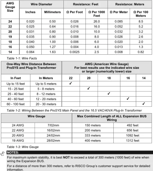
About Wire
The proper use of wire and cable is necessary for the successful installation and operation of the ProSYS system. It is important to select wire of the correct thickness to minimize power loss and ensure reliable system operation. Take into account both the installation's current requirements and the wiring distances involved. The following tables provide useful information to help make your installation trouble-free.
ETL NOTES:
Wiring shall be done according to the National Electrical code ANSI/NFPA 70. Use a min gauge of 22AWG for all wiring.
Wire Diameter Resistance: Feet Resistance: Meters AWG
Gauge
Size Inches Millimeters Ω Per Foot Ω Per 1000
Feet Ω Per Meter ΩMeters Per 100
24 0.020 0.50 0.026 26.0 0.085 8.5 22 0.025 0.64 0.016 16.0 0.052 5.2 20 0.031 0.80 0.010 10.0 0.032 3.2 19 0.035 0.90 0.008 8.0 0.026 2.6 18 0.040 1.00 0.006 6.0 0.020 2.0 16 0.050 1.27 0.004 4.0 0.013 1.3 14 0.064 1.63 0.0025 2.5 0.008 0.82
Table 1-1: Wire Facts
One-Way Wire Distance Between
ProSYS and Plug-In Transformer For best results use the indicated wire size AWG (American Wire Gauge) or larger (numerically lower) size In Feet In Meters 22 20 18 16 14 Up to 15 feet Up to 5 meters 15 - 25 feet 5 - 8 meters 25 - 40 feet 8 - 12 meters 40 - 60 feet 12 - 20 meters 60 - 100 feet 20 - 30 meters
Table 1-2: Wiring Between the ProSYS Main Panel and the 16.5 VAC/40VA Plug-In Transformer
Wire Gauge Max Combined Length of ALL Expansion BUS Wiring
24 AWG 7/02mm 150 meters 492 feet
22 AWG 16/02mm 200 meters 656 feet
20 AWG 24/02mm 333 meters 1092 feet
19 AWG 28/02mm 400 meters 1312 feet
Table 1-3: Wire Gauge NOTES:
For maximum system stability, it is best NOT to exceed a total of 300 meters (1000 feet) of wire when wiring the Expansion BUS.
For a distance of more than 300 meters, refer to RISCO Group’s customer support service for detailed information.
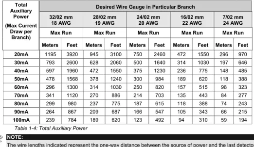
Desired Wire Gauge in Particular Branch 32/02 mm
18 AWG 28/02 mm 19 AWG 24/02 mm 20 AWG 16/02 mm 22 AWG 7/02 mm 24 AWG Max Run Max Run Max Run Max Run Max Run Total Auxiliary Power (Max Current Draw per Branch)
Meters Feet Meters Feet Meters Feet Meters Feet Meters Feet 20mA 1195 3920 945 3100 750 2460 472 1550 296 970 30mA 793 2600 628 2060 500 1640 314 1030 197 646 40mA 597 1960 472 1550 375 1230 236 775 148 485 50mA 478 1568 378 1240 300 984 189 620 118 388 60mA 296 1300 314 1030 250 820 157 515 98 323 70mA 341 1120 270 886 214 703 135 443 84 277 80mA 299 980 237 775 187 615 118 388 74 243 90mA 264 867 209 687 166 547 105 343 66 215 100mA 239 784 189 620 123 492 94 310 59 194 Table 1-4: Total Auxiliary Power
NOTE:
The wire lengths indicated represent the one-way distance between the source of power and the last detector in the branch.
Desired Wire Gauge in Particular Branch
32/02 mm 28/02 mm 24/02 mm 16/02 mm Max Run Max Run Max Run Max Run Max External
Siren Current (Max current draw per
branch)
Meters Feet Meters Feet Meters Feet Meters Feet 100mA 238 780 191 625 151 495 94 310 200mA 229 390 95 313 76 248 47 155 300mA 79 260 63 208 50 165 31 103 400mA 59 195 48 157 38 124 24 78 500mA 48 156 38 125 30 99 19 62 650mA 37 120 29 96 23 76 15 48 Table 1-5: Maximum External Siren Current
NOTE:
The wire lengths indicated represent the one-way distance between the ProSYS and the external siren in the branch.
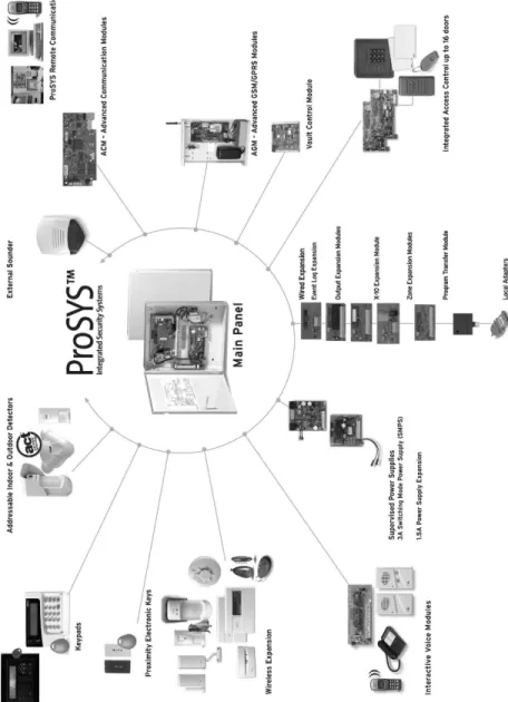
ProSYS Architecture and Capabilities
The following diagram provides an overview of the ProSYS's architecture and capabilities. Examine this figure before beginning your ProSYS installation to obtain an overall picture of the full extent of the ProSYS system's capabilities.
ProSYS Features
This section describes the features of the ProSYS system, including features specific to each ProSYS model.
Feature-Specific Limitations
Each ProSYS model has several feature-specific limitations, as described in the following table:
Feature ProSYS 16 ProSYS 40 ProSYS 128
Total Zones 8-16 8-40 8-128
Main Expansion Zones (wired or wireless) 1x8 (EZ or WR) 4x8 or 2x16 or 2x8 + 1x16 (EX or WR) 1x8 + 7x16 (EX or WR)
Max BUS Zones 16 32 32
Max Current 1,5 A 1,5 A 1,5 A
Number of Expansion BUSes 2 2 2
Total Number of Expansion
Modules 64 (32 for each data BUS) 64 (32 for each data BUS) 64 (32 for each data BUS)
Box NC Tamper Input 1 1 1
Bell Tamper EOL Input 1 1 1
Total Utility Outputs 6-22 6-38 6-70
Utility Output Expansion Modules Up to 2 modules (max 16 UO) Up to 4 modules (max 32 UO) Up to 8 modules (max 64 UO) Partitions/Areas 4 4 8
Groups Per Partition/Area 4 4 4
User Codes 00-29 00-59 00-98
Access Control Modules
(# of Doors) 2 (4 doors) 4 (8 doors) 8 (16 doors)
Proximity Key Reader 16 16 16
Keypads 8 12 16
Account Numbers 8 8 12
Follow Me Numbers 8 8 16
Event Log 256 Built-in (No
Possible Expansion) 512 (with Expansion) 999 (with Expansion)
GSM/GPRS Communication Module 1 1 1 IP Communication Interface (ACM) 1 1 1 NOTES:
The zone expansion modules can be either with wire or wireless.
All panels can work with a battery of up to 17AH according to the applicable regulations. The relay output should have the option to supply COM positive -12V or negative -0V.
Main Panel
The Main Panel is the foundation of the system's operation and has the following features: ♦ 8 basic hardwired zones
♦ 6 Utility Outputs:
1 x relay (programmable output) (3 Amps) 1 x 500mA transistor (Open Collector) 4 x 70mA transistors (Open Collector) ♦ Box tamper input (normally open)
♦ Bell tamper input (using a 2.2KΩ end-of-line resistor)
♦ Two different 4-wire BUSes with "quick connectors" from the Main Panel, which is the initial point for all system. If one BUS is shorted or there is any kind of problem that interrupts the BUS data, the other one continues to operate normally
♦ Power for the operation of an external sounder
♦ Offers the required type of voltage for one or more electronic sirens, bells, or loudspeakers, respectively
♦ Supports more than 20 zone types
♦ 6 zone terminations, including: closed-circuit (NC), open-circuit (NO), end-of-line (EOL) resistors, double end-of-line (DEOL) resistors, triple end-of-line (TEOL) resistors (refer also to Chapter 2, Mounting and Wiring the Main Panel) and BUS zone.
♦ Event log (on board up to 256 events)
Zone Expansion
♦ Support for additional 16 (ProSYS 16), 32 (ProSYS 40) or 120 (ProSYS 128) wired or wireless zones
♦ 8-Zone or 16-Zone wired/wireless-868MHz expansion modules
♦ 6 zone terminations, including closed-circuit (NC), open-circuit (NO), end-of-line (EOL) resistors, double end-of-line (DEOL) resistors and triple end-of line(TEOL) resistors ♦ BUS zones support and BUS Zones expander
♦ Supports more than 20 zone types ♦ Forced setting zone capability
Wireless Devices
When using wireless zones, the ProSYS 8/16 Wireless expansion modules respond to different wireless detectors, such as:
♦ PIR/PET detectors ♦ Smoke detectors
♦ Door contacts/Door magnet/universal transmitter/door contact +universal ♦ Up to 32 rolling code 4-buttons keyfobs
♦ Double key panic keyfob ♦ Flood detector
♦ Shock detectors ♦ CO detectors ♦ Gas detectors ♦ Glassbreak detectors
The Wireless expansion module includes the following features: ♦ Super heterodyne technology
♦ Programmable supervision time ♦ Tamper detection
♦ Low battery in transmitters detection ♦ Signal jamming indication
♦ Programmable supervision time
Partitions/Areas
♦ Up to 8 independent partitions/areas
♦ Any zone can be assigned to any partition/area
♦ Each partition/area supports both zone sharing and cross zoning. ♦ Each partition/area can be assigned with its own account number
Groups
Groups are combined zones within a partition/area that are used for partial arming. ♦ Up to four groups of zones can be defined for each partition/area.
♦ Group arming is performed by using the Function keys on the keypad (A, B, C, and D). Each key represents a different group of zones.
♦ Each zone can be assigned to any of the 4 groups ♦ Users can arm any of the four groups individually
♦ Group setting is performed by using the function keys on the keypad or using a keyfob
Keypads
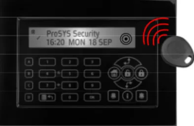
The ProSYS can support up to 16 keypads, with a choice of four styles (LCD, two LED types, and one LCD proximity type) from which virtually all system features can be accessed.
Figure 1-2: LCD Keypad
Each keypad is equipped with:
♦ Three Emergency Key zones (Panic, Fire, and Auxiliary Emergency) ♦ The ability to produce a Duress (Ambush) Code
♦ Double tamper-protected ♦ Internal buzzer
♦ Audible feedback for keypad operations
♦ Easy-to-use hot-key sequences for simple zone bypassing ♦ A one-key Quick-Arm feature for both "Stay" and "Away"
♦ In partitioned systems, keypads can be selectively assigned to specific partitions ♦ 4 function keys (A,B,C,D) can be programmed to carry a sequence of commands
User Codes and Authority Levels
♦ 1 engineer code♦ 1 sub engineer code ♦ 1 Grand Master code
♦ Up to 99 user codes (ProSYS 128) ♦ 8 Authority levels
♦ Double code option for high security
♦ Codes can be defined to 4 or 6 digits (By default 6 digits)
Programmable Utility Outputs
♦ Supports additional 16 (ProSYS 16), 32 (ProSYS 40) or 64 (ProSYS 128) outputs ♦ 4-relay or 8-transistor expansion output modules
♦ Outputs operation follows system events, codes or scheduling programs. ♦ Output can follow up to 5 zone events (All/Any definition)
♦ X-10 Module: The ProSYS also supports the connection of an X-10 Transmitter module to its 4-wire Expansion BUS. X-10 technology converts the ProSYS's programmable output events into a protocol understood by the Transmitter module. When triggered, this module generates activation and control signals along existing AC premises wiring to the appropriate X-10 Receiver modules, appropriately placed and connected within the premises to control lighting and appliances. X-10 Transmitter modules are available for the ProSYS, supporting either 8- or 16-premises Receiver modules.
Communication
♦ On-board Digital Communicator
♦ Numerous transmission formats to MS including ADEMCO Contact ID and SIA. ♦ Account number for each partition with additional backup accounts.
♦ 3 MS link up options using: PSTN report GSM report IP report GPRS report SMS report
♦ Flexible split reporting for backup
♦ Call Save mode from which non-urgent reports can be collected over a designated time period and then transmitted all at once (windowing), and support daily system testing, along with reports of entry into, and exit from, the system's Installer Programming mode
♦ Follow Me report: In addition to standard communication with the MS, the ProSYS employs a Follow-Me feature in which the system can report a homeowner at work, or a business owner at home, that there has been an alarm at a specific location by voice message over the phone, SMS or Email.
Advanced Digital Voice Module
The Advanced Digital Voice module provides audible information about the status of your ProSYS system and enables any remote, touch-tone (DTMF) telephone to act as a keypad for the system. The Advanced Digital Voice Module can be used in the following situations: ♦ Upon event occurrence, such as alarm activation, the Advanced Digital Voice module
informs you of a security situation, such as intrusion or fire, by calling you and playing a pre-recorded Event announcement. You can then acknowledge the event and remotely operate the system.
♦ Remotely operating the system, which includes: Partition arming and disarming
Zone bypassing
UO activation/deactivation Changing Follow-Me numbers
Performing Listen and Talk options that enable you to listen in to your property and talk back, if necessary
Power Supply Expansion Module
Although the ProSYS's Main Panel provides 600mA of auxiliary power (900mA for Bell), the use of a number of additional system modules and detectors will likely exceed this limitation. As a result, the ProSYS permits the addition of up to eight remote Power Supply expansion modules, each operating from AC power and connected to the BUS.
There are 2 types of power supply modules. One provides a total current capacity of 1.5 Amps and the other is a switched power supply that provides a total current capacity of 3 Amps. Both modules have connections for powering auxiliary devices and triggering bells, electronic sirens, or loudspeakers during an alarm. Each Power Supply expansion module also supports its own standby battery and is supervised for the loss of AC, a low battery condition, tamper input, the failure of its auxiliary output power, and the loss of sounder loop integrity.
Access Control Expansion Module
One of ProSYS's most unique features is its integration with an Access Control sub-system. With a maximum connection of eight such Access Control modules, a total of 16 readers is possible (each module supporting up to two readers). Each reader can operate with magnetic, proximity, bar code, touch, and/or Weigand technology. Up to 999 users can be accommodated, and up to 1000 "transactions" can be stored in a module.
Scheduling
Through the use of the system's built-in clock, it is possible to automate system operations at the same time on selected days of the week or at a specific time within the subsequent 24-hour period or during vacation periods.
The system operations include:
♦ Scheduling automatic arming and disarming (of one or more partitions). ♦ Scheduling automatic operation of Utility Outputs.
Event Logging
The ProSYS has the capability of storing up to 999 significant events, including arming, disarming, bypassing, alarms, troubles, restorals, and resets. These events are logged in order according to date and time, and when applicable, according to Zone, Partition, Area, User Code, Keypad, etc. When appropriate, such events can be displayed on an LCD keypad or uploaded to the MS via the Upload/Download software and printed for further analysis.
Printer Module
A Printer module, designed to interface between the ProSYS's 4-wire Expansion BUS and a Centronics-type parallel printer, enables the printing of all significant system events as they occur, including access control activities, if applicable. Each event includes the date, time and if applicable, the affected partition and the user involved.
Advanced Installation Tools
♦ Auto Installation: For quick and easy installation, the system performs automatic installation of the modules connected to the BUS. The system searches for the modules by automatically verifying their connection and operation through the BUS-scanning feature and prompts the user to approve each module connection. The auto installation feature is performed automatically after defaulting the system or can also be performed manually.
♦ Self Monitoring
The BUS Test enables the system to verify the connection and the operation of the modules connected to the BUS by indicating the efficiency of each one on a 0-100% scale. Each result is individually displayed on the LCD keypad (or via the Upload/Download software).
A watchdog feature, which periodically and automatically performs a comprehensive self-test and reports when operating faults are found. A Maintenance Mode which, when selected, performs an active self-check on
many of its components.
One-man walk testing capabilities, enabling an Installer or technician to check the operation of each contact and detector which, when tripped, produces audible feedback and is visibly logged at the keypad from which the test was initiated.
♦ System programming Local keypad keys
Program Transfer Module: Used to store the programmed configuration of any ProSYS without the need for power.
Local/Remote Upload/Download software
False Alarm Reduction
In an effort to deter false alarms, the ProSYS provides various programmable features, including the following programmable features: cross zoning, swinger shutdown, audible/visual entry/exit delays, fire alarm verification, dialer delay before an alarm transmission, cancel report option, double knock, soak test and exit termination zone.
Chapter 2: Mounting and Wiring the Main
Panel
This chapter covers the first two steps of the ProSYS installation procedure, as follows:
♦Step 1: Mounting the Main Panel, below
♦Step 2: Wiring the Main Panel, page 2-3
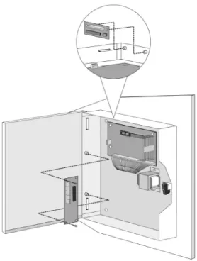
Step 1: Mounting the Main Panel
The ProSYS Main Panel . should be installed inside a metal box Attach the box to the wall using the proper hardware, as shown below.
Figure 2-1: Mounting the Main Panel The mounting location should be:
♦ Dry.
♦ Near an AC power supply (switched off).
♦ With a good earth connection.
Safety Precautions
When mounting the Main Panel, the following safety precautions are relevant:
♦ When the Main Panel is powered on, mains voltage is present on the main PCB. To prevent risk of electric shock, disconnect all power (AC transformer and battery) and phone cords before servicing. Under no circumstances should mains power be connected to the PCB other than to the main terminal block.
♦ For AC mains connection, a readily accessible disconnect device shall be incorporated in the building installation wiring.
♦ The equipment should be installed in accordance with the National Fire Protection Association's Standard #74 (N.F.P.A. Batterymarch Park, Qulncy, MA 02269) and local National Electrical Codes.
♦ For continued protection against risk of fire, replace fuses only with fuses of the same type and rating.
♦ There is a risk of explosion if a battery is replaced with an incorrect type. Dispose of used batteries according to the proper instructions. (The Main Panel is designed to work with a 12 V, 7 Amp-hour sealed lead battery as a backup for the primary power supply.)
♦ Do no short the terminals of the transformer together. This causes the internal fuse to blow. The transformer must be connected to a 230 VAC, 24-hour outlet not controlled by a switch other than an approved over-current protection device.
♦ The Main Panel is designed with reverse polarity protection on the battery charging circuit. However, prolonged improper connection of the battery to the Main Panel will result in damage. The power should remain disconnected until all connections have been made and checked for accuracy.
Discharging Static Electricity
Please note that it is important to discharge static electricity that may have built up in your body before you touch a circuit. To do this, touch the earth. (Refer also to What Makes a Good Ground? in Chapter 2, Mounting and Wiring the Main Panel.)
Following Local Regulations
Be sure to follow your local regulations regarding fire protection, electrical installation, noise pollution, and security systems installation.
What Makes a Good Ground?
Grounding provides a degree of protection against lightning and induced transients for any piece of electronic equipment that may, due to lightning or static discharge, experience permanent or general malfunctions. The ideal ground is considered to be a unified earth ground in which an 8-foot copper-clad rod, located close to the existing power and telephone ground rods, is sunk several feet into the earth. Appropriate hardware and clamps are then used to electrically connect each of these rods together and then to the ground terminal of the device to be protected.
It may be possible to use an existing electrical ground on the premises if one is close enough to the Main Panel. Ideally, that ground can be obtained at the metal service panel where the incoming electrical power originates. When connecting the ground wire, use a solid 14-gauge wire [or larger (numerically lower) size] connected between the ProSYS'sGND terminal and an acceptable electrical ground connection. Keep this wire as short as possible and do not run it in conduit, coil it, bend it sharply, or run it alongside other wiring. If you must bend it or change its direction, it should have a radius of at least 8 inches at the point from which it is bent. If in doubt, you may want to enlist the help of a licensed electrician in matters concerning such grounding.
Step 2: Wiring the Main Panel
This step explains the various wiring and connection procedures that must be performed when wiring the Main Panel, as follows:
♦Wiring the Main Panel,page 2-3
♦Wiring the Zones to Sensors and Detectors (Zone Terminals Z1 through Z8), page 2-4
♦Wiring the Auxiliary Devices, page 2-6
♦Wiring the Bell Sounders, page 2-7
♦Wiring the Bell Tamper, page 2-7
♦Wiring the Box Tamper, page 2-8
♦Wiring External Triggerable Devices, page 2-8
♦Connecting the J10 Connector, page 2-9
♦Connecting to Ground (Earth), page 2-10
♦Connecting Telephone Lines, page 2-10
♦Jumper Settings, page 2-11
♦Connectors, page 2-12
♦Connecting AC Power, page 2-12
IMPORTANT: Before wiring the Main Panel, ensure that the connection to the power supplies, mains or battery, is switched OFF during wiring.
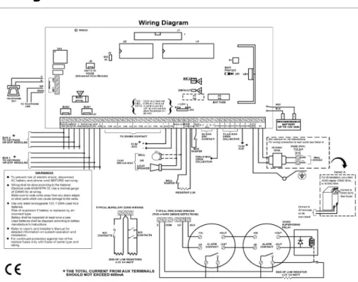
Wiring the Main Panel
The second set of four terminals on the left of the Main Panel represent the Expansion BUS. These support the connection of keypads and expansion modules.
The connections are terminal-to-terminal with color-coded wires, as follows: BUS Terminal Description
AUX RED +12V power for BUS expansion modules COM BLK Black 0V common for BUS expansion modules BUS YEL Yellow DATA connection for BUS expansion modules BUS GRN Green DATA connection for BUS expansion modules
To prevent a possible drop in voltage due to multiple keypads and long wire runs, use a quality 4-conductor cable with an appropriate gauge size (refer to the table of gauge sizes in
Chapter 1, Introducing ProSYS).
The parallel wiring system supports parallel connections from any point along the wiring (refer to Figure 2-3 below). The maximum wire run permitted is 300 meters (1000 feet) for all legs of the BUS.
Figure 2-3: 4-Wire Expansion BUS
NOTE:
The ProSYS has 2 separate BUS connections. If one BUS is shorted or there is any kind of problem that interrupts the BUS data, the other BUS will continue to operate normally.
Wiring the Zones to Sensors and Detectors
(Zone Terminals Z1 through Z8)
¾
To wire the zones to sensors and detectors:1. Connect up to 8 hardwired zones, using twisted-pair or 4-conductor cablewiring. 2. Connect each zone to the appropriate Zone (Z) terminal and its related COM terminal.
Each pair of zones shares a COM terminal. For example, Z1 and Z2 share a COM terminal, as do Z3 and Z4, and so on.
NOTES:
It is recommended that you use an End-of-Line Resistor at the far end of each hardwired zone to prevent short-circuits (16 resistors are supplied).
For a zone with a tamper switch, you can use a Double End-of-Line Resistor to save additional Main Panel connections (refer to
Figure 2-4 on page 2-6).
3. Terminate unused zones at the Main Panel.
4. Connect the power to the sensors and/or detectors, as described in Wiring the Auxiliary Devices, page 2-6.
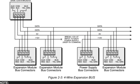
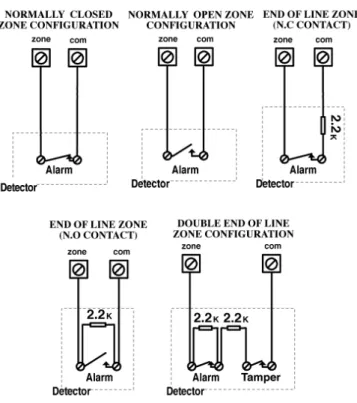
The following diagrams illustrate the various possible zone connections depending on the zone expanders.
Connections on Zone Expanders (ProSYS EZ8, ProSYS EZ16):
Figure 2-4: Zone Connection Diagrams
Wiring the Auxiliary Devices
¾
To wire auxiliary devices:♦ Use the Auxiliary Power AUX (+) COM (-) terminals to power PIRs, glass-break detectors (4-wire types), smoke detectors, audio switches, photoelectric systems and/or any device that requires a 12V DC power supply.
NOTES:
The total power from the AUX terminals should not exceed 600mA.
To connect a 4-wire smoke detector or devices that require resetting after an alarm condition, connect the Auxiliary power AUX and UO terminals (refer to Figure 2-2 on page 2-3, for smoke detector wiring). Remember to define the UO as Switched Auxiliary (refer to the Switch AUX parameter described in Chapter 5, Quick Key [3][1][14]). Using the Installer Programming Menus).
In addition, when connecting a 4-wire smoke detector, observe the wiring guidelines mentioned in the previous sections, along with any local requirements applicable to smoke detectors.
To prevent a possible drop in voltage due to current requirements and distances involved, make sure to use the appropriate wire gauge (refer to the table of gauge sizesin Chapter 1, Introducing ProSYS). To increase your power supply when employing multiple auxiliary devices, you can use the optional Power Supply expansion module (refer to the Wiring Power Supply Expansion Modules section in Chapter 3, Installing External Modules and Devices).
If the auxiliary outputs are overloaded (exceed 600mA) and are shut down, you must disconnect all loads from the outputs for a period of at least 10 seconds before you reconnect any load to the auxiliary outputs.
Wiring the Bell Sounders
¾
To wire the bell sounders:1. Connect a suitable wire to the internal sounding device(s) inside the building (bell, electronic siren, or loudspeaker).
2. Ensure that you note the polarity when connecting electronic siren(s) and/or polarized bells.
!
WARNING: To avoid Bell Loop Trouble, if NO connection is made to an internal sounder, use a 2200Ω resistor in its place.
NOTE:
It is important to position the BELL/LS Jumper (J3) correctly. The position varies depending on the type of internal sounder.
3. For a loudspeaker without a built-in sound driver, position the jumper J3 so that it covers both pins. The Main Panel produces a continuous oscillating voltage for burglary and panic alarms and an interrupted oscillating voltage for fire alarms.
4. For a bell or an electronic siren with a built-in sound driver, position the jumper J3 so that it does NOT cover both pins. A steady 12V DC is produced at the sounder terminals during burglary and panic alarms. A slow pulsing voltage is produced during a fire alarm.
Wiring the Bell Tamper
¾
To wire the bell tamper:♦ Connect the bell tamper to the BELL TMP and COM terminals on the Main Panel, as illustrated in Figure 2-2 on page 2-3.
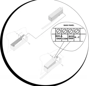
Wiring the Box Tamper
¾
To wire the box tamper:♦ Connect the box tamper to the BOX TMP and COM terminals on the Main Panel, as illustrated in Figure 2-2 on page 2-3. Refer also to the diagram shown below.
Figure 2-5: Wiring the Box Tamper
Wiring External Triggerable Devices
¾
To wire external triggerable devices:♦ Wire the external triggerable devices that you want to activate to the outputs UO1-UO6, as follows:
UO1: Refer to the J10 connector instructions, described in the next section. For additional details, refer to Chapter 3, Installing External Modules and Devices.
UO2-UO6: Connect the positive connection of the device to AUX (+) and the negative connection to the UO's (-) terminals.
Connecting the J10 Connector
POS NEG Figure 2-6: Connecting the J10 Connector
The J10 connector (jumper) determines the UO1 connection (behavior), which is normally used for an external siren connection, as follows:
♦Positive (POS): When the J10 connector is placed on POS, the C terminal on UO1 receives 13.8V.
NOTE:
The maximum current for UO1 and the bell should not exceed 900mA.
♦Negative (NEG): When the J10 connector is placed on NEG, the C terminal on UO1 receives COM.
Connecting to Ground (Earth)
¾
To connect to ground (earth):♦ Connect the metal box and the door of the metal box to mains earth (ground), as shown in the diagrams on the following page. Refer also to What Makes a Good Ground?, page 2-2. !
IMPORTANT:
Connecting to ground must be performed according to the local National Electrical Code.
Figure 2-7: Grounding the Metal Box Figure 2-8: Grounding the Metal Box Door
Connecting Telephone Lines
These lines are typically derived from an installed RJ31X jack.
¾
To connect telephone lines:1. Connect the incoming telephone line to the Main Panel's LINE terminals. 2. Connect any telephone on the premises to the SET terminals.
Jumper Settings
The ProSYS is equipped with internal jumpers. Use the following table to configure the jumpers according to the desired configuration.
Jumpers Position Function
Enables to default the panel and restore the ProSYS codes (Grand master, installer and sub installer) to the manufacturers default settings.
Position the jumper plug over both pins when reinstating factory installed defaults values to the Grand master, installer and sub installer codes or for installing programming using the Program Transfer Module (refer to Chapter 4, Programming the ProSYS).
DEFAULT (J2)
(Default)
Maintains the last programming setting and disables the restoring of the ProSYS codes (Grand master, installer and sub installer) to the manufacturers default settings.
Position the default jumper plug over one pin for safekeeping.
The J3 jumper determines whether a bell or loudspeaker sound will be heard.
Loudspeaker: The ProSYS produces a continuous or interrupted oscillating voltage, depending on the type of alarm.
BELL/ LOUDSPEAKER
(J3)
(Default)
Bell: The ProSYS produces a steady 12V DC voltage or a slow pulsating voltage, depending on the alarm type. Refer to Wiring the Bell Sounders, page 2-7, for further details
(Default)
Battery Discharge Protection is Activated: If a continuous AC power outage occurs, the ProSYS automatically disconnects the battery when its backup battery voltage drops below 10.05 VDC, in order to prevent "deep discharge” that may damage the battery.
NOTE:
In this position, the ProSYS will not start to operate from a battery power supply, unless connected to the Mains first. BATTERY
PROTECTION (J20)
Battery Discharge Protection is Disabled; The battery may be totally discharged during continuous AC failure, thus battery replacement may be required (no deep discharge protection).
NOTE:
In this position, the ProSYS will start to operate from a battery power supply whether it is connected to the Mains or not.
UO1 (J10)
Determines the UO1 connection (behavior), see Connecting the J10 Connector, page 2-9. Default: 1 PIN
Connectors
Connector Function
J1, J5 BUS 1 Plug in connector. J8 BUS 2 Plug in connector.
J4 SIG In connector. The J4 SIG IN voice connector enables the transfer of audio data between the Voice module RP200VC and the phone line.
J6
The J6 connector is used to connect the Advanced Digital Voice Module (rp128ev00uka) to the ProSYS.
Connect the Voice module to the VOICE connector (J6) on the Main Panel via the supplied cable. This connector transmits signals from the Voice module to the telephone line during remote communication and is essential for normal operation of the Voice module.
Connecting AC Power
¾
To connect AC power:1. Connect the 230V AC to the mains fuse (SLOW BLOW 315 mA) input terminal block according to the Local National Electronic Code.
2. Fasten the AC cord to the metal box using adjustable clamps. !
IMPORTANT:
Do NOT apply mains power at this time.
Be sure to connect the live wire of the AC power through the AC fuse. The size of the conductors must not be less than 0.75mm2 (18AWG).
Chapter 3: Installing External Modules and
Devices
This chapter describes steps 3 to 5 of the ProSYS installation procedure, as follows: ♦ Step 3: Identifying and Wiring Keypads and Expansion Modules ♦ Step 4: Adding Modules, page 3-3
♦ Step 5: Applying Power, page 3-7
Step 3: Identifying and Wiring Keypads and
Expansion Modules
This section explains how to program a unique ID number to identify each keypad and expansion module in the system and how to install a keypad, as follows:
♦ Programming Device ID Numbers, below ♦ Installing a Keypad, page 3-2
Programming Device ID Numbers
¾
To program device ID numbers:♦ Program each device's ID number by setting the dip switches, as follows:
ID 1 2 3 4
01 OFF OFF OFF OFF 02 ON OFF OFF OFF 03 OFF ON OFF OFF 04 ON ON OFF OFF 05 OFF OFF ON OFF 06 ON OFF ON OFF 07 OFF ON ON OFF 08 ON ON ON OFF 09 OFF OFF OFF ON 10 ON OFF OFF ON 11 OFF ON OFF ON 12 ON ON OFF ON 13 OFF OFF ON ON 14 ON OFF ON ON 15 OFF ON ON ON 16 ON ON ON ON Figure 3-1: Dip Switch Settings
Assign the same ID numbers to the different categories of devices (meaning keypads and expansion modules) in the order they are added to the system.
This means that you must assign the ID of 01 to the first keypad as well as to the first Zone Expander, the first Utility Output and the first Power Supply module. A second module in any of these categories receives the ID of 02. Up to 16 keypads can be added to the system, each assigned ID numbers from 01 to 16. Up to 8 of the other types of devices can be added to the system, each assigned ID numbers from 01 to 08.
Installing a Keypad
NOTE:
For information on installing the Touchscreen keypad, refer to the ProSYS Touchscreen Keypad Instruction manual that is included with the product.
¾
To install a keypad:1. Open the Keypad Cover: Remove the back of the keypad cover, and using a screwdriver, press in each of the retaining clips to separate the back cover from the keypad. Take care not to touch the circuitry of the keypad buttons.
2. Set the Dip Switches: Program the keypad ID by setting the dip switches according to the table displayed in Figure 3-1 on page 3-1. Dip switch settings are per ID number (01 = first keypad, 02 = second keypad, and so on).
3. Connect the BUS Wiring: Connect the wires from the appropriate terminals in the keypad to the appropriate connector on the Main Panel's Expansion BUS terminals. The connections are terminal-to-terminal with the terminals clearly marked. The wires are color-coded, as follows:
EXPANSION BUS TERMINALS AUX COM BUS BUS
Color RED BLK
(Black) (Yellow)YEL (Green) GRN
UP
Orientation arrow Wall fixing points
Back panel Tamper protected fixing
point
Figure 3-2: Keypad Installation Front View
NOTES:
A trimmer is located on the right side of the keypad (next to the dip switches) that enables you to adjust the brightness and contrast of the LCD display. Therefore, it is recommended to leave the keypad open while powering up in order to adjust the LCD display.
To prevent a possible drop in voltage due to multiple keypads and long wire runs, use a quality 4-conductor cable with an appropriate gauge size (refer to the table of gauge sizes in Chapter 1, Introducing ProSYS).
4. Set the Tamper Switch: Before mounting the keypad on the wall, locate the rear-mounted Tamper Switch and make sure that it is vertically oriented. 5. Replace the Cover:
Carefully replace the keypad's printed circuit board in its cover.
Join the cover and base by hooking the tops together and then snapping the bottom in place, returning the retaining clips to their positions.
Step 4: Adding Modules
This section explains how to add the various ProSYS modules, as follows: ♦ Wiring Zone Expansion Modules, below
♦ Wiring Utility Output Modules, page 3-4
♦ Wiring Power Supply Expansion Modules, page 3-6 ♦ Wiring Additional Modules, page 3-7
Wiring Zone Expansion Modules
Figure 3-3: 8 Zone Expansion Module Figure 3-4: 16 Zone Expansion Module
¾
To wire Zone expansion modules:1. Set the Dip Switches: Assign a unique ID to each Zone expansion module by setting the dip switches, using Figure 3-1 on page 3-1.
NOTE:
The ID for the first Zone expansion module is 01, for the second 02, and so on.
2. Connect the BUS Terminals: Connect the first four terminals at the left of the Zone expansion module to the Main Panel's 4-wire BUS terminal, as follows:
EXPANSION BUS TERMINALS AUX COM BUS BUS
Color RED BLK
(Black) (Yellow)YEL (Green) GRN
NOTES:
The parallel wiring system supports parallel connections from any point along the wiring (refer to Chapter 2, Mounting and Wiring the Main Panel).
The maximum wire run permitted is 300 meters (1000 feet) for the total BUS wiring. 3. Connect the Zone Terminals (8-Zone Expander Z8; 16-Zone Expander
Z1-Z16): Refer to steps 1 to 3 in the Wiring the Zones to Sensors and Detectors section in
Chapter 2, Mounting and Wiring the Main Panel.
4. Supply Power to the Auxiliary Devices: Refer to step 4 in the Wiring the Zones to Sensors and Detectors section in Chapter 2, Mounting and Wiring the Main Panel.
Wiring Utility Output Modules
Figure 3-5: Utility Output Module UO4 (Showing an Example of UO4 Wiring)
Figure 3-6: Utility Output Module E08 Figure 3-7: Utility Output Module X-10
¾
To wire Utility Output modules:1. Set the Dip Switches: Assign a unique ID to each Utility Output expansion module by setting the dip switches, using Figure 3-1 on page 3-1.
NOTE:
The ID for the first Utility Output expansion module is 01, for the second 02, and so on. The first Utility Output in the Utility Output expansion module (defined as ID 01) will always be Utility Output 07. 2. Connect the BUS Terminals: Connect the first four terminals at the left of the Utility
Output expansion module to the Main Panel's 4-wire BUS, as follows: EXPANSION BUS TERMINALS
AUX COM BUS BUS Color RED BLK
(Black) (Yellow)YEL (Green) GRN
NOTES:
Additional Utility Output modules can be connected to the system at any available point on the Expansion BUS wiring (refer to Chapter 2, Mounting and Wiring the Main Panel).
3. Set the Tamper (TAMP COM): The Utility Output expansion module can be contained in a metal cabinet. Tamper the cabinet, as follows:
Connect one (or more) normally open (NO) momentary-action pushbutton switches in a series between the TAMP and COM terminals in order to short-circuit these terminals while the cabinet door is closed.
NOTES:
It is not necessary to use a tamper switch if another module sharing the same cabinet is equipped with one.
Do NOT use an End-of-Line Resistor in the tamper switch circuit.
If a tamper switch is not used, connect a wire jumper between the two terminals. 4. Mount the Utility Output Expansion Modules: Mount one or more Utility Output
expansion modules in the Main Panel cabinet, depending on space availability. Alternatively, mount them in a separate cabinet.
5. Connect the Triggerable Device to the Utility Output:
Connect one wire to the COM terminal of the UO device to be operated and connect the other wire to the GND.
Connect the NO or NC switch to the AUX terminal.
6. Wire the Relay Connections: The Relay module has 4 relays (UO1, UO2, UO3, and UO4), which can be connected as follows:
Connect one wire of the device to be operated to the UO terminal. Connect the other wire of the device to be operated to the AUX terminal.
For instructions about programming the relay operation, refer to the Utility Output
section in Chapter 5, Using the Installer Programming Menus.
7. Wire the Triggers: The Open Collector modules have 8 outputs (UO1 through UO8). For instructions about programming their operation, refer to the Utility Output section in Chapter 5, Using the Installer Programming Menus.
8. Wire the X-10:
Connect the 4-wire BUS between the Main Panel and the X-10 module.
Connect an RJ25 cable (4-wire telephone cable) between the RJ11 connector on the X-10 module and the X-10 transmitter.
Plug the X-10 transmitter into the AC power.
Plug the X-10 receiver into the AC power close to the device that will be operated. Connect the X-10 receiver to the device.
For more information about programming and setting the ID of the X-10 module, refer to the instructions supplied with the module
Wiring Power Supply Expansion Modules
ON 1234 ON OFF SW1 BELL LS(PS LED) (UO LED)
AC AUX RED BELL LS+ -TAMP BUS YEL GRN COM BLK BUS BELL/LS (Bell/Loudspeaker Jumper) OC
(Over Current LED) BAT (Battery Jumper) PS Battery Connections Loudspeaker/ Bell Power to Accessories and Detectors Transformer 1 2 3 4 1 2 3 4 ON N.O C N.C U O 1 C U O 2 N.O N.C
Figure 3-8: 1.5A Power Supply Module PS Figure 3-9: 3A Power Supply Module PS
¾
To wire Power Supply expansion modules:1. Set the Dip Switches: Assign a unique ID to each Power Supply expansion module by setting the dip switches, using Figure 3-1 on page 3-1.
NOTE:
The ID for the first Power Supply expansion module is 01, for the second 02, and so on.
2. Connect the BUS Terminals: Connect only three of the first four terminals at the left of the Power Supply expansion module to the Main Panel's 4-wire BUS, as follows (refer also to Figure 2-3 in Chapter 2, Mounting and Wiring the Main Panel):
EXPANSION BUS TERMINALS COM BUS BUS Color BLK
(Black) (Yellow)YEL (Green) GRN !
IMPORTANT:
Do NOT make any connection to the AUX (RED) terminal from the Main Panel. It is used for the outgoing BUS to supply voltage to other modules.
NOTES:
The Power Supply expansion module is connected to the AC power supply. This module, therefore, supplies power to all modules and/or keypads located AFTER the point that it is connected to the BUS. The maximum wire run permitted is 300 meters (1000 feet) for the total BUS wiring.
3. Set the Tamper (TAMP COM): The Power Supply expansion module can be contained in a metal cabinet. Tamper the cabinet, as follows:
Connect one (or more) normally open momentary-action pushbutton switches in a series between the TAMP and COM terminals.
NOTES:
It is not necessary to use a tamper switch if another module sharing the same cabinet is equipped with one.
If a tamper switch is not used, connect a wire jumper between the two terminals. 4. Connect the Internal Siren BELL/LS (+) (-):
Connect a suitable wire to the internal device(s) to be driven by the Power Supply expansion module (bell, electronic siren, or loudspeaker).
Use a larger wire gauge if the distance separating the siren and the module is significant. Take the siren(s) current draw into account as well when selecting a wire gauge (refer to the table of gauge sizes in Chapter 1, Introducing ProSYS).
NOTE:
Any internal siren(s) connected to the Power Supply expansion module will operate exactly like the siren(s) connected to the Main Panel.
Position the BELL/LS Jumper (J3), as follows:
♦ For a loudspeaker without a built-in siren driver, position the jumper J3 so that it covers both pins. The module produces a continuous oscillating voltage for burglary and panic alarms and an interrupted oscillating voltage for fire alarms. ♦ For a bell or electronic siren, with a built-in sound driver, position the jumper J3 so
that it does NOT cover both pins. A steady 12V DC is produced at the siren terminals during burglary and panic alarms. A slow pulsing voltage is produced during a fire alarm.
5. Supply Power to the Auxiliary Device AUX (+) COM (−): The Power Supply expansion module can power PIRs, glass-break detectors (4-wire types), audio switches, and photoelectric systems. It can also power any device located too far from the Main Panel and/or whose operation requires a continuous supply of 12V DC via the AUX (+) and COM (−) terminals. (Refer to Chapter 2, Mounting and Wiring the Main Panel).
6. Connect the Flying Leads (RED and BLACK): Connect these leads (at the proper time) to the positive (+ RED) and negative (− BLACK) terminals of the appropriate Standby Battery for the Power Supply expansion module.
Wiring Additional Modules
For details about wiring the following modules, refer to the installation and programming manual that is supplied with each module:
♦ Advanced Digital Voice Module ♦ Access Control Module ♦ Proximity Key Reader ♦ Fast PSTN Modem 2400 BPS ♦ ProSound Sounder
♦ Advanced Communication Module (ACM) ♦ GSM/GPRS Module (AGM)
♦ BUS Zones detectors (WatchOUT, Lunar Industrial, WatchIN, iWise) ♦ BUS Zone Expander
Step 5: Applying Power
After you have completed wiring the modules, you can apply power and program the system according to the instructions in the next chapter.
Chapter 4: Programming the ProSYS
This chapter explains the ProSYS programming options, how to use the keypad elements, and the basics about programming via the keypad, as described in the following sections: ♦ Using the ProSYS Main Panel Programming Options, below
♦ Using the LCD Keypad, page 4-2
♦ Programming from the LCD Keypad, page 4-4 ♦ Using the Program Transfer Module, page 4-9
For detailed information about each Programming option, refer to Chapter 5, Using the Installer Programming Menus.
Using the ProSYS Main Panel Programming Options
You can program the ProSYS in any of the following ways:♦ LCD Keypad: Use any of the LCD keypads described in this manual. Each keypad needs a unique ID to identify it in the system. Refer to Chapter 3, Installing External Modules and Devices, for details about how to set the keypad ID using dip switches. Instructions for programming the ProSYS from an LCD keypad are provided on pages 4-2 through 4-8. ♦ Program Transfer Module (PTM): (Model ProSYS EE) The PTM is a tiny circuit board into which a copy of the Main Panel's configuration can be copied and stored as well as transferred to any installation when temporarily plugged into its 4-wire BUS. Refer to page 4-9 for detailed instructions about using the Program Transfer Module.
♦ Upload/Download (U/D): This is a software application that enables you to program the ProSYS from a PC computer. It offers the following two alternatives:
Working locally, through a portable computer connected to the Main Panel
Working at a remote site, communicating with the Main Panel via one of the following options:
Y A phone line and modem
Y TCP/IP network using the ACM module Y GPRS using the AGM a phone line and modem
When using the Upload/Download software, the following is required: Y IBM compatible PC
Y Upload/Download software
Y BUS adapter cable and plug to connect between the PC serial COM port and the ProSYS J1 connector (for on-site use)
Y Modem with access to a phone line (for remote use)
Y USB/485 converter for on-site use (p/n RP128EUSB00A) to connect between a PC USB port and the ProSYS J1 serial connection. For additional details, refer to a RISCO Group’s technical support representative.
Full details and operating instructions for the U/D software are available in the
Using the LCD Keypad
#/
?Figure 4-1: The LCD Keypad Face
The LCD keypad is a visual interface tool that helps you operate the ProSYS Main Panel. The LCD keypad contains six LED indicators and a variety of keys. Their typical uses are described in the following table:
NOTE:
For information regarding the TouchScreen keypad please refer to the instructions supplied with the product.
Item Key/LED Programming Mode/Function 1 Power LED This LED indicates the following:
• LED ON = power on
• Slow flashing LED = an active programming session • Fast flashing LED = system trouble
2 Arm LED This LED indicates that the system is armed. All partitions must be disarmed (LED unlit) to enter the Installer Programming mode.
3 Ready LED 4 Bypass LED 5 Fire LED 6 Tamper LED
These LEDS are off (unlit) during programming operations. These LEDs on the keypads (other than the one being used for actual programming) flash during programming operations.
Item Key/LED Programming Mode/Function
7 A, B, C, and D Use these keys for defining groups and macros. Refer to the
Groups section in Chapter 1, Introducing ProSYS for further details.
8 Use this key to exit the current programming selection and move up to the next higher level in the programming hierarchy. 9 LCD Program
Display The LCD program display consists of two lines. The top line displays information about the main selection mode, and the bottom line displays information and/or data about the specific option set. Such data may be changed through keypad entry. When programming, up to 16-characters can be entered into a line, as required.
10 0 through 9 Use the numbered keys, 0 through 9, to key in numbers and/or special characters when labeling zones, areas, and partitions. (For information about how to use the keypad for labeling zones, areas, and partitions, refer to Chapter 5, Using the Installer Programming Menus.)
11
/ /
Press either one of these keys to move back and forth through the programming level functions.
These keys also change the position of the flashing cursor. When editing a selection, the cursor moves to the left or right respectively.
12
/ Use this key to toggle forward through the programming choices within a selection. 13
/ Use this key to toggle backward through the programming choices within a selection. 14
/ Use this key to enter selected information into the system or to accept the current selection and access the lower level of options in the programming hierarchy.
Programming from the LCD Keypad
This section explains how to use the keypad to access the Installer Programming menu as well as how to restore the manufacturer's defaults, as described in the following sections: ♦ Accessing the Installer Programming Menu, below
♦ Restoring Manufacturer's Programming Defaults, page 4-6 ♦ Keypad Timeout, page 4-8
♦ Using the Program Transfer Module (PTM), page 4-9
Accessing the Installer Programming Menu
This section describes how to access the Installer Programming menu for the first time or after the Main Panel has been defaulted, as well as how to access it from the regular operation mode.
If the Main Panel has been defaulted, you must enter the Installer Programming menu as if it is the first time. In this case, after you enter your Installer code, the system automatically enters the automatic accessories setting process by performing the BUS scan. (Refer to the
Accessories: Auto Settings section of Chapter 5, Using the Installer Programming Menus for further details).
¾
To access the Installer Programming Menu for the first time (or after the Main Panel has been defaulted):1. When you power up the system, the following display appears: PLEASE WAIT…
PLEASE WAIT…
After a brief wait, the following display appears:
TO INSTALL TO INSTALL PRESS * PRESS * TO INSTALL TO INSTALL PRESS * PRESS *
2. To program the system to recognize the keypad, press . The following display appears, prompting you for the Installer code:
3. Enter the default Installer code, depending on the ProSYS model:
ProSYS 128: [0][1][2][8]
ProSYS 40: [0][1][4][0]
ProSYS 16: [0][1][1][6]
The code appears as 4444 on the keypad display, as follows:
4. The system enters the automatic accessories setting process, and the following display appears:
NOTE:
Refer to Accessories: Auto Settings section of Chapter 5, Using the Installer Programming Menus for further details.
The Power/ LED begins flashing slowly at this point, indicating that you have entered a programming session.
¾
To access the Installer Programming Menu from the regular operation mode: 1. When you power up the system, the following display appears:PLEASE WAIT… PLEASE WAIT…
After a brief wait, the keypad displays the regular operation mode, as follows:
2. Press . The keypad displays the first User Functions option, as follows:
3. Press [7] to select the Installer option or use the / key. The keypad
displays the first option, as follows:
4. Press [1] Advanced. The keypad prompts you for the Installer code, as follows:
5. Enter the default Installer Code, depending on the ProSYS model:
ProSYS 128: [0][1][2][8]
ProSYS 40: [0][1][4][0]
ProSYS 16: [0][1][1][6]
The code appears as 4444 on the keypad display, as follows:
6. Press / . The keypad displays the following message:
Then the first main Installer Programming menu option is displayed, as follows:
The Power/ LED begins flashing slowly at this point, indicating that you have entered a programming session.
The main Installer Programming menu options are available, as follows: [1] SYSTEM [2] ZONES [3] UTIL OUTPUT [4] CODE MAINT [5] DIALER [6] REPORT CODES [7] ACCESSORIES [8] MISCELLANEOUS [9] ACCESS CONTROL [0] EXIT PROGRAM
Each of the main Installer Programming menu options enables you to access and program all of the ProSYS options. Refer to Appendix E, Installer Programming Maps for a complete list of all the programming options. Each option is also discussed in detail in
Chapter 5, Using the Installer Programming Menus.
Restoring Manufacturer's Programming Defaults
You may find it useful to be able to remove all changes made to the Main Panel's programming and restore the default settings provided by the manufacturer. Restoring defaults requires performing both of the procedures below. The first procedure enables the restoring option and the second procedure is the actual restoring process.¾
To enable the restore to the manufacturer's defaults:1. From the Installer Programming menu,select the System option by pressing [1] or pressing the / key. The System menu option is displayed, as follows:
2. Select the Default Enable/Disable option by scrolling down to the option using the
/ key or press [7]. The following display appears:
3. Toggle to the Default Enable option using the / key until the following is displayed:
NOTE:
The Default option for the Default Enable/Disable parameter is Enable.
4. Select the option by pressing the / key. NOTE:
5. Press and then press [0]. The keypad prompts you to save the changes by displaying the following message:
6. Confirm saving the data by pressing the / key. A short beep will sound, and the keypad displays the following messages:
7. Next, the system will perform a Tamper Test. The following display appears:
TESTING: TESTING: PLEASE WAIT PLEASE WAIT TESTING: TESTING: PLEASE WAIT PLEASE WAIT
If a tamper occurs in the system (Bell, box or other) the display will show a list of the tamper faults in the system.
It is advisable to scroll down the list and fix the tamper before exiting the installer programming mode to prevent tamper alarm.
8. After reviewing the tamper fault list press / key. The following display appears: Quit with Tamper? N Quit with Tamper? N
Selecting Yes will result in exiting the installer programming menu and activating a tamper alarm in the system.
When the save function is complete and no tamper fault exists, the keypad displays the regular operation mode, as follows:
If, while exiting, the following display appears, this means that the J2 default jumper on the Main Panel is NOT in its position on one of the J2 pins, but wrongly positioned on both J2 pins.