Augmented reality for robots:
virtual sensing technology
applied to a swarm of e-pucks
Andreagiovanni Reina, Mattia Salvaro
∗, Gianpiero Francesca,
Lorenzo Garattoni, Carlo Pinciroli, Marco Dorigo, Mauro Birattari
IRIDIA, Universit´e Libre de Bruxelles, Brussels, Belgium [email protected], [email protected]
Abstract—We present a novel technology that allows real robots to perceive an augmented reality environment through
virtual sensors. Virtual sensors are a useful and desirable tech-nology for research activities because they allow researchers to quickly and efficiently perform experiments that would otherwise be more expensive, or even impossible. In particular, augmented reality is useful (i) for prototyping and assessing the impact of new sensors before they are physically produced; and (ii) for developing and studying the behaviour of robots that should deal with phenomena that cannot be easily reproduced in a laboratory environment because, for example, they are dangerous (e.g., fire, radiations). We realised an augmented reality system for robots in which a simulator retrieves real-time data on the real environment through a multi-camera tracking system and delivers post-processed information to the robot swarm according to each robot’s sensing range. We illustrate the proposed virtual sensing technology through an experiment involving 15 e-pucks.
I. INTRODUCTION
Swarm robotics [1] is a promising discipline that studies the coordination of a large number of robots to perform tasks in several domains. Real-world applications that would benefit from swarm robotics-based solutions include search and rescue, demining, nanoparticle medical treatments, space or underwater construction. However, the complexity and unpredictability of these applications exceeds the capabilities of current swarm systems, which are developed in totally controlled lab conditions. While, on the one hand, robot swarms promise characteristics such as scalability, robustness, adaptivity and low-cost, on the other hand, robot swarms are complex to analyse, model and design because of the large number of nonlinear interactions among the robots. Mathematical and statistical tools to describe robot swarms are still under development, and a theoretical methodology to forecast the swarm dynamics given the individual robot behaviour is missing [2]. As a consequence, it is common practice to resort to empirical studies to assess the performance of robot swarms.
Experiments may be either in simulation or with physical hardware. The former are easier to run and less time consum-ing than the latter. However, when experiments are performed only in simulation, they may not guarantee that the estimated performance matches the one measured with real hardware.
∗MS is also with Universit`a di Bologna, Italy.
In contrast, experiments with robots demonstrate and confirm that the investigated system functions on real devices, which include challenging aspects intrinsic of reality and out of the designer’s control, such as noise and device failures. However, experimentation with physical hardware is expensive, both in terms of money and time. In addition, hardware modifications are impractical and often impossible to realise when time and money resources are limited. We believe that a viable solution to these issues is performing hybrid experiments that combine real robots with simulation. This work proposes a novel technology to endow a robot swarm with virtual sensors, immersing the robots in an augmented reality environment.
We envision two useful applications of augmented reality for robots: (i) prototyping new sensors to endow the robots with additional sensing capabilities, and (ii) adding virtual el-ements in the experimental environment. Concerning point (i), through the proposed virtual sensing technology, a robot swarm can be quickly endowed with a new sensor and the new resulting swarm behaviour can be tested before the sensor is produced. Compared to the production and installation of a real sensor, implementing a virtual sensor is much quicker, cheaper and easier, since it is built entirely in software and installed by uploading the code on the robot. Therefore, several tests can be done before the actual production of the sensor. This prototyping approach is particularly advantageous when operating with a swarm of robots. In fact, hardware production and installation for a large number of robots may be expensive and requires a considerable amount of work. Concerning point (ii), a researcher can design a virtual environment with the desired characteristics and allow a robot swarm to perceive that environment. This use case permits studies in hard-to-reproduce experimental conditions because of costs or risks involved. For instance, the proposed technology allows the simulation of harmful radiations in a nuclear accident site (or flames diffusion in a fire), and enables the robots to perceive the simulated radiations (or temperature) through a virtual sensor. In particular, the proposed technology allows a researcher to simulate environments that evolve in time with arbitrarily complex temporal patterns. This allows the study of systems that are required to adapt to changes in their operational environment.
To enable virtual sensing, we designed an architecture composed of three components: a tracking system, a simulator and a robot swarm. The tracking system provides the simulator with the location and orientation of each robot in real time. 978-1-4673-7501-6/15/$31.00 © 2015 IEEE
On the basis of this information, the simulator computes the readings of the virtual sensors. The simulator then delivers the readings into the robots via wireless communication. To illustrate the system, we performed an experiments in which a swarm of 15 e-pucks senses and acts in a real environment, augmented with features of a virtual counterpart.
The rest of the paper is organised as follows. In Section II, we give an overview of the state of the art in virtual sensing technology. In Section III, we describe the architecture of the system. In Section IV, we describe the experiment that we perform to illustrate the system. In Section V, we discuss the proposed technology and we suggest possible future work.
II. RELATED WORK
A number of works devoted attention to the subject of virtual sensing technology. O’Dowd et al. [3] and Bjerknes et al. [4] implemented a specific virtual sensor to perform robot localisation. In both cases, the authors adopt a tracking or positioning system to import the robots’ position in a simulator. O’Dowd et al. [3] used a tracking system and WiFi communication to supply the robots with their position. Thus, virtual sensor technology has been implemented only as a specific virtual GPS sensor. Bjerknes et al. [4] developed a 2D and 3D positioning system based on ultrasonic beacons. Through triangulation, the robots can calculate their position autonomously. Bjerknes et al. [4] achieved decentralised and scalable virtual sensing employing an embedded simulator running on each robot. This solution would not be viable for robot swarms, due to the limitations of the hardware in terms of memory and computation power. In this work, virtual sensors are not transparent to the control software that has to allocate power and time resources for the virtual sensor computation. Furthermore, the ultrasonic positioning system requires hardware modification, in particular ultrasonic sensors are installed on each robot. In contrast to these two systems, we propose a general architecture that enables the implementation of any kind of virtual sensor, requiring only WiFi communication hardware on the robots involved. While, in the literature, the virtual sensors are ad-hoc implementations to be used only in a specific experimental setup, here we propose a general-purpose technology for virtual sensing.
Although this paper does not deal with virtual actuation, we report here the main works on the topic as it is relevant in the context of augmented reality. In the literature, there are a few works that propose an interaction between robots and virtual environment based on virtual actuators. Among those who implemented virtual actuation, Sugawara et al. [5] and Garnier et al. [6] developed a system in which robot deposit virtual pheromone. Once deposited, the pheromone is visualised using coloured light projections on the floor. Both works, employed a tracking system, a projector, and additional light sensors installed on the top of the robots. Thus, the proposed approaches require both custom hardware on the robots and a smart environment based on a light projector. The approaches require controlled light conditions: in particular, ambient light needs to be reduced to a minimum to allow the robots perceive the light emitted by the projector. Khaliq et al. [7] implemented virtual pheromone using a grid of radio frequency identification tags (RFID) embedded in the floor, each tag being an hexagonal portion of the grid. The robots
TABLE I: List of components and respective acronym.
Acronym Component
ATS Arena tracking system
ATS-PE Arena tracking system physics engine ATS-S Arena tracking system server
ATS-C Arena tracking system client VS-S Virtual sensor server VS-C Virtual sensor client
VS-SM Virtual sensor simulation module VS-RRM Virtual sensor real robot module
are equipped with a RFID transceiver and are able to write and read the value of the tag they are standing on. Khaliq et al. [7] achieved a scalable system because the information is externalised and spatialized throughout the RFID tag grid: the robots only elaborate local information and there is no need of central control and computation. However, a smart environment and specific hardware on the robots must be provided for the realisation of only one specific virtual actuator.
III. ARCHITECTURE
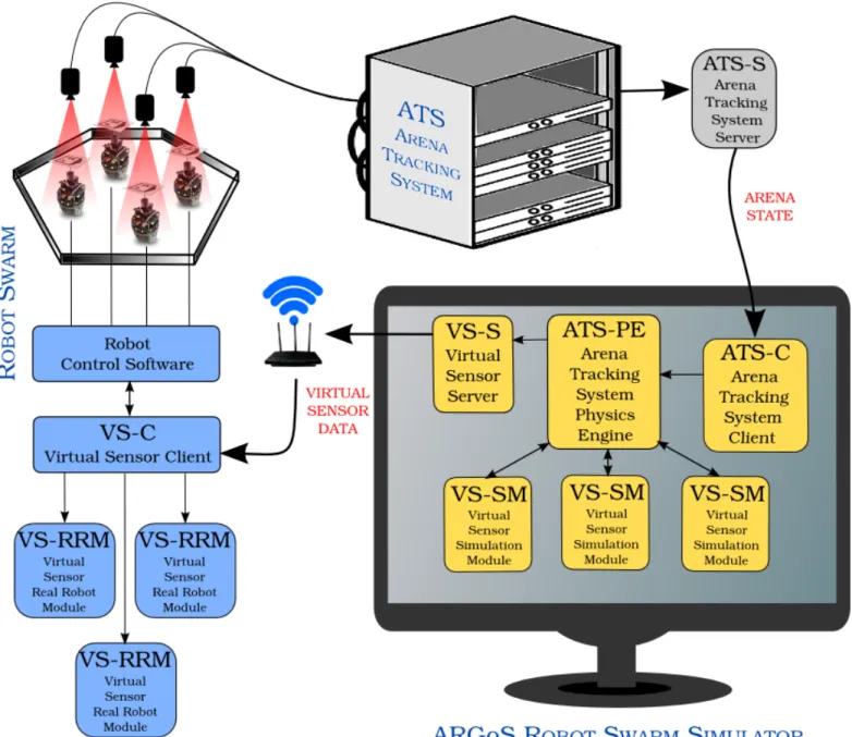
In this section, we detail the components of the system and their communication protocols, following the logical flow from the source of the information (tracking system) to the final “user” of the virtual sensors (the robots). Figure 1 shows the information flow between the components, while Table I lists the components of the virtual sensing architecture and provides their respective acronym.
Similarly to the works mentioned in Section II, our system is based on a tracking system that computes the robots’ positions, i.e., their locations and orientations, in real time. The tracking system streams the robots’ data to a simulator which, in turn, computes the readings of the virtual sensors. Next, the simulator sends the computed readings to the robots, according to their sensing ranges. Finally, the robots access the readings to choose the next actions to perform.
A. Arena tracking system
The developed virtual sensing architecture can work with any tracking system that supplies real-time location and orien-tation of the robots. In this work, we employ thearena tracking system(ATS) [8], a multi-camera tracking system developed at the IRIDIA lab. The ATS is composed of a 4×4 matrix of HD cameras and a dedicated 16-core server which runs custom software based on the Halcon libraries for machine vision1.
The camera matrix covers an area of about 10×7m2.
Between each pair of neighbouring cameras there is an over-lapping region that is covered by both cameras. The overlap between cameras allows the ATS to robustly handle the track-ing of robots that move between two cameras’ field-of-view. The tracking software transparently manages image merging and robot tracking: it receives as input an XML configuration file and returns as output the robots’ position list. The input configuration file allows a user to select the active cameras and
Fig. 1: Graphical representation of the proposed virtual sensing technology.
to tune each camera parameters to perform tracking at different speeds and under different light conditions.
The arena tracking system detects the robots through paper printed markers placed on the top of the robots. The markers are composed of a matrix of 6 cells (2×3), similar to a very simple QR code. This setup yields 64 different configurations; all of them are valid configurations that the ATS recognises. This markup method has the advantage of rendering it simple and quick to setup an experiment. In fact, the markers can be printed by any black-and-white printer on standard paper and there are no configurations in mutual exclusions or algorithms to compute the set of valid configurations, any subset of the 64 ones is valid.
Large coverage area, ease of configuration, and large max-imum swarm size are the main features that characterise the
ATS with respect to other tracking systems [8]. Nevertheless, every tracking system can be used for our virtual sensing system, as long as the tracking system returns the location and orientation of the robots in real time.
The set of positions of each robot, i.e., locations and orientations, identifies the arena statewhich is transmitted to the swarm robotics simulator to compute the virtual sensor readings (see Section III-B). The communication between the ATS and the simulator is achieved through a client/server architecture on TCP/IP. The ATS provides a server named
arena tracking system server(ATS-S) that waits for connections from the simulator. The connection must happen before the robot experiment begins. Once connected, the ATS-S sends to the simulator the last computed arena state at its maximum tracking rate. Since image processing time is variable, the
tracking rate is not constant and the server transmits the new arena state as soon as it is computed. Until a new arena state is received, the simulator uses the last known arena state. During our experiment, the arena state transmission average period is about 90 ms, which determines an acceptable rate for our purposes.
B. Robot swarm simulator: ARGoS
The robot simulator we use is ARGoS [9], a modular physics-based simulator tailored for swarm robotics. One of the main features of ARGoS is its modularity, which allows a user to extend the simulator by developing custom plugins. We exploited ARGoS modularity by implementing a custom physics engine named arena tracking system physics engine
(ATS-PE) that controls the motion of the simulated robots. A physics engine is the simulator module dedicated to compute and update at each timestep the world state, including the robots positions.
The ATS-PE is the focal point of the whole virtual sensor architecture. Through the ATS-PE, the control of the ex-periment is transferred from reality to simulation. ATS-PE connects to the ATS-S to receive the arena state from the tracking system, and updates with this information the position of the simulated robots. Then, ARGoS computes the virtual sensor readings for each simulated robot. When the virtual sensor readings have been computed, the ATS-PE transmits them to the (real) robots, and finally the robot control software reads these values as if they were from normal sensors.
While the ATS runs on a dedicated high-performance machine, the simulator can run on a general-purpose com-puter without affecting the overall system performance. To communicate with the tracking system and the robots, ATS-PE includes a client calledATS client(ATS-C), and a server called
virtual sensor server(VS-S). The ATS client is a thread respon-sible for establishing a connection to the ATS through ethernet LAN, and periodically receives the arena state. The arena state is encapsulated in a data structure organised according to a double-buffer design. The double buffer guarantees the consistency of the arena state and minimises the duration of the lock session on the data structure. The ATS client stores the computed arena state in one buffer and updates the other one. At the end of the procedure, the ATS client swaps the buffers.
The VS-S executes a thread that constantly waits for robot connections. Upon establishing a connection, the VS-S sends the robot the necessary information to initialise the virtual sensor. Robots can connect dynamically to the virtual sensor server in any stage of the experiment through a thread running on them, called virtual sensor client (VS-C). At the end of each simulation timestep, the VS-S transmits the virtual sensor readings to the corresponding robots. The duty of serialising and deserialising the data structure is delegated to the imple-mentation of the single virtual sensor (see Section III-C).
C. Virtual sensors
A virtual sensor is composed of two software modules: one module running in the ARGoS simulator that computes the sensor’s readings, (calledvirtual sensor simulation module,
VS-SM) and a second module running on the robot that allows
the control software to receive the virtual sensor readings (virtual sensor real robot module,VS-RRM).
The simulation module is similar to a simulated sensor: it uses robot position and simulated environment information to compute the sensor reading at each timestep. Additionally to a classic simulated sensor, the VS-SM extends a generic virtual sensor interface which provides the functionality of serialising the reading values and copy them to the output buffer of the VS-S (see Section III-B).
The VS-RRM appears to the robot control software as a normal sensor, however its readings do not result from a dedicated hardware component, instead the readings are retrieved from the input buffer of the VS-C. Similarly to the VS-SM, the VS-RRM implements the virtual sensor interface that provides the specular functionality of deserialising the readings received from the VS-C’s input buffer.
We tailored the virtual sensor interface and the virtual sensor client for the e-puck robot [10], a small-size wheeled robot. Decoupling the virtual sensor server from the virtual sensors data structure releases the virtual sensor designer of any constraint regarding the data structure, allowing him/her to apply an arbitrary level of complexity. In addition, through the proposed architecture, the robot control software accesses virtual sensor readings in a transparent way, in fact, at robot control software level, there is no distinction between real and simulated sensors.
As stated above, one of the main advantages of the pro-posed technology is the simplicity of implementing a new vir-tual sensor. Through the proposed technology, providing robots with novel sensing capabilities requires a very small amount of work because, once the infrastructure is in place, most part of the components do not need any further modification. In fact, to add a new virtual sensor, it is sufficient to implement the VS-SM and VS-RRM modules and register the new sensor’s name in the VS-C and VS-S. Most of this implementation is straightforward and automated; the crucial part is the design and implementation of (i) the data structure that embeds the virtual sensor readings (e.g., a single real number vs. a list of nbits), and (ii) the logic that ARGoS will use to compute these readings given the robot position and the environment state.
IV. ROBOT EXPERIMENT
We illustrate the architecture presented above through an experiment in which a swarm of 15 e-pucks equipped with virtual sensors is able to perceive an augmented reality en-vironment. In this experiment, the robots are equipped with a virtual pollutant sensor. The pollutant is simulated via ARGoS. The sensor returns a binary value indicating whether there is a presence of pollutant at the robot location. In our experiment, we assume that the pollutant is present in an area within a diffusion cone with vertex located at the pollutant source σ. The diffusion cone is characterised by the direction angle θd that indicates the direction of diffusion, the cone width θw. The parametersθd andθw are defined at the beginning of the experiment by the user. In contrast, the location of the pollutant source σis defined through an ATS marker placed in the real environment, therefore, it is computed at runtime and may change during the experiment. In the implemented pollutant
TABLE II: Parameter values used in the robot experiment.
θd 10◦ θr 100◦
θw 45◦ Tr 60 s
Ps 0.3
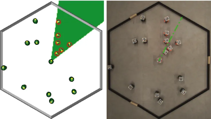
diffusion model, we included a time variant component which turns the direction angle θd of θr degrees counterclockwise afterTrseconds from the beginning of the experiment. Table II shows the parameter values we have used for our experiment. The same robot control software runs on all the robots of the swarm. The software encodes a very simple robot behaviour that has been designed with the purpose of offering an easy-to-understand experiment that illustrates the proposed technology. The robots move randomly within an hexagonal arena and, when a robot perceives the pollutant (i.e., it lies within the diffusion cone defined above), it stops and lights up its red LEDs with probability Ps= 0.3per timestep. Figure 2 shows two screenshots of the experiment and the full video can be found at https://youtu.be/7QAWi5JDwzA.
In this setup, the robots receive noiseless readings from their virtual sensors; however, if desired, a virtual sensor can be designed with a more realistic characterisation to include noise. Despite its simplicity, we deem this pollutant diffusion experiment sufficient to illustrate the elements of the architecture and showcase one of the main advantages of virtual sensing. We show the possibility of a cheap, quick and safe implementation that enables experimentations in scenarios involving dangerous components. The polluted environment we present is a simple example of the type of scenarios that are normally very complex to setup within a laboratory; however, through virtual sensing, experiments in such a scenario can be performed with very limited effort. Additionally, in the presented experiment, the pollutant diffusion model includes a time-variant component that illustrates the possibility of performing experiments in environment that changes over time according to any user defined model.
V. CONCLUSIONS AND FUTURE WORK
In this paper, we presented a novel technology to enable augmented reality for robots via virtual sensing. We proposed an architecture based on a tracking system, a simulator and virtual sensor modules running on the robots. The proposed architecture allows a robot swarm to perceive in real time an augmented reality environment that may include components difficult or impossible to create within a lab. These extended capabilities pave the way for novel types of experimentation with robot swarms. For example, an envisioned case study includes the simulation of radioactive emissions in a nuclear disaster site. The use of time-variant features is particularly useful to perform experiments that investigate the swarm flexibility on external changes, e.g., changes of environmental features. Additionally, the proposed technology allows one to prototype novel sensors prior to their production. This procedure may reduce the risk of wrong hardware production by allowing the preliminary verification of the functioning of the algorithms of interest.
A limitation of the proposed technology is that it does not operate in environments where objects taller than the robots
occlude the field of view of the ATS ’s ceiling cameras. For instance, experiments involving walking humans may hinder the proper functioning of the system because in certain situations the human body may interfere with the tracking of the robots.
Future developments include furthering the design of our systems, endowing it with virtual actuators capable of modify-ing the augmented reality. A viable approach currently under study to achieve this result is to close the communication loop between the robots and the simulator. In other words, the virtual action of a robot consists in the delivery of a message from the robot to the simulator. The latter, in turn, processes the message and applies the modification to the simulated environment. In this way, the modification becomes available for virtual sensing by the rest of the swarm.
The realisation of virtual actuation would bring the same advantages given by the virtual sensing technology, applied on actuators instead of sensors. We could prototype actuators as we can do for sensors, and additionally we could perform experiments in fully dynamic virtual environments that change in response to the robot actions. An appealing idea is to implement virtual actuators that, while impossible to install on the e-puck (or similar low-cost robots), would enable complex and affordable experimental studies on swarm dy-namics. For instance, from the combination of virtual sensing and actuation, experiments with virtual pheromone would be easy accessible and would facilitate studies on the role of stigmergy in self-organisation. Virtual sensing and actuation technology offers a clean, flexible and software based solution to investigate, by means of real robots experiments, fields of swarm robotics that have been prerogative of simulation.
ACKNOWLEDGMENT
This work was partially supported by the European Re-search Council through the ERC Advanced Grant “E-SWARM: Engineering Swarm Intelligence Systems” (contract 246939). Marco Dorigo and Mauro Birattari acknowledge support from the Belgian F.R.S.-FNRS. We thank Bernard Mayeur for helping in refactoring the code of the virtual sensor modules.
REFERENCES
[1] M. Dorigo, M. Birattari, and M. Brambilla, “Swarm robotics,” Scholarpedia, vol. 9, no. 1, p. 1463, 2014. [2] M. Brambilla, E. Ferrante, M. Birattari, and M. Dorigo,
“Swarm robotics: A review from the swarm engineering perspective,”Swarm Intelligence, vol. 7, no. 1, pp. 1–41, 2013.
[3] P. J. O’Dowd, A. F. T. Winfield, and M. Studley, “The distributed co-evolution of an embodied simulator and controller for swarm robot behaviours,” inIROS. IEEE, 2011, pp. 4995–5000.
[4] J. D. Bjerknes, W. Liu, A. F. Winfield, C. Melhuish, and C. Lane, “Low cost ultrasonic positioning system for mobile robots,” Proceeding of Towards Autonomous Robotic Systems (TAROS 2007), pp. 107–114, 2007. [5] K. Sugawara, T. Kazama, and T. Watanabe, “Foraging
Behavior of Interacting Robots with Virtual Pheromone,” inProceedings of IEEE/RSJ International Conference on Intelligent Robots and Systems. Los Alamitos, CA: IEEE Press, 2004, pp. 3074–3079.
Fig. 2: Screenshot of the running experiment: On the left, the simulated environment in ARGoS and, on the right, an aerial view of the robots, with an overlay representing the pollutant cone. The simulated robot positions matches with the real robot ones. The object placed in the center of the arena represents the pollutant source σand, in the simulated environment, the green cone highlights the area where robots perceive the pollutant. In the real environment, robots within the pollutant cone perceive the pollutant through their virtual sensors and light up their red LEDs with probability Ps.
[6] S. Garnier, F. Tache, M. Combe, A. Grimal, and G. Ther-aulaz, “Alice in pheromone land: An experimental setup for the study of ant-like robots,” Swarm Intelligence Symposium. SIS 2007. IEEE., pp. 37–44, 2007.
[7] A. A. Khaliq, M. D. Rocco, and A. Saffiotti, “Stigmergic algorithms for multiple minimalistic robots on an RFID floor,” Swarm Intelligence, vol. 8, no. 3, pp. 199–225, 2014.
[8] A. Stranieri, A. Turgut, M. Salvaro, L. Garattoni, G. Francesca, A. Reina, M. Dorigo, and M. Birat-tari, “IRIDIA’s arena tracking system,” IRIDIA, Univer-sit´e Libre de Bruxelles, Brussels, Belgium, Tech. Rep. TR/IRIDIA/2013-013r004, 2015.
[9] C. Pinciroli, V. Trianni, R. O’Grady, G. Pini, A. Brutschy, M. Brambilla, N. Mathews, E. Ferrante, G. A. Di Caro, F. Ducatelle, M. Birattari, L. M. Gambardella, and M. Dorigo, “ARGoS: a modular, parallel, multi-engine simulator for multi-robot systems,” Swarm Intelligence, vol. 6, no. 4, pp. 271–295, 2012.
[10] F. Mondada, M. Bonani, X. Raemy, J. Pugh, C. Cianci, A. Klaptocz, S. Magnenat, J.-C. Zufferey, D. Floreano, and A. Martinoli, “The e-puck, a robot designed for education in engineering,” inProceedings of the 9th Con-ference on Autonomous Robot Systems and Competitions, 2009, pp. 59–65.