Physical-Layer Attacks in Optical WDM Networks
and Attack-Aware Network Planning
Marija Furdek
Dept. of Telecommunications, Faculty of Electrical Engineering and Computing, University of Zagreb, Croatia Phone: +38516129731, Email: [email protected]
Abstract—The high data rates employed by WDM transparent optical networks make them most suitable for today’s growing network traffic demands. However, their transparency imposes several vulnerabilities in network security, enabling malicious signals to propagate from the source to other parts of the network without losing their attacking capabilities. Furthermore, detecting, locating the source and localizing the spreading of such physical-layer attacks is more difficult since monitoring must be performed in the optical domain. Most failure and attack management approaches are reactive and focus on network recovery after a fault or an attack has already occurred. Recently, novel, prevention-oriented safety strategies have been proposed to aid attack localization and source identification in the planning phase.
This paper provides a summary of optical network component vulnerabilities which can be exploited to perform attacks to the proper functioning of the network and a description of known methods of such attacks. Furthermore, it gives an overview of network planning approaches which deal with the physical-layer security issues in transparent optical networks and emphasises the need for new, preventive strategies for increasing safety in transparent optical networks.
Index Terms—Transparent optical networks; Routing and Wavelength Assignment; Physical-layer attacks
I. INTRODUCTION
The best way of accommodating the intensively growing network traffic and satisfying the ever tighter demands on throughput, delay and overall network performance is by using optical fiber technology. Optical fiber is characterized by huge bandwidth of up to 50 THz, low BER of10−12, low loss of down to 0.2 dB/km and low noise and interference characteristics. The best way of exploiting this immense potential is by dividing it among independent sets of different wavelengths, which is the underlying principle of Wavelength Division Multiplexing (WDM). Each wavelength supports one communication channel, operating independently at an arbitrary speed. Independently modulated wavelengths are all multiplexed and carried simultaneously over the same physical fiber. Transparent Optical Networks (TON) enable all-optical channels, called lightpaths, to be established between any pair of nodes. Due to the wavelength routing network capabilities, a lightpath can span multiple physical links without undergoing opto-electronic-optical (OEO) conversion at the intermediate nodes it traverses. This creates a virtual topology over the given physical topology, in a process called Routing and Wavelength Assignment (RWA).
Network transparency, given its advantageous insensitivity to data rates and protocol formats, has a crucial drawback
when it comes to network safety. Namely, full 3R (re-amplification, re-shaping, re-timing) signal regeneration in the optical domain is still in experimental phase. At the moment, optical signals can only be re-amplified (1R), while re-shaping and re-timing require OEO conversion. In the absence of OEO conversion, a signal does not get regenerated or even interpreted at any intermediate node so it can propagate through parts of the network even in cases when variations in its modulation, intensity or bandwidth are out of bounds of “regular” signal characteristics for a given protocol. In networks with full 3R regeneration, an anomalous signal would either get discarded or misinterpreted by a regenerating node, resulting in further propagation of an erroneous signal, but with characteristics within the bounds of the network modulation format. In TONs, however, a malicious signal can spread uncontrollably. Combined with difficulties related to the monitoring in the optical domain, all of this significantly decreases network robustness and requires more sophisticated methods of error prevention, detection and correction.
The outline of the paper is as follows. Section II describes some of the common network planning approaches and points out the recent trends in their design. Section III characterizes and classifies attacks in transparent optical networks, followed by an overview of specific attack methods which exploit op-tical network component vulnerabilities in section IV. Section V identifies key issues in fault and attack management in transparent optical networks, while suggestions of possible avenues of future work conclude the paper.
II. ROUTING ANDWAVELENGTHASSIGNMENT The Routing and Wavelength Assignment problem consists of two subproblems: finding the physical routes for the given lightpath demands in the Routing (R) part of the problem, and assigning a wavelength to each of them in the Wavelength Assignment (WA) subproblem. Most common objectives of the RWA process include minimizing the number of physical hops in the established lightpaths or lightpath congestion (R), or minimizing the number of wavelengths used (WA). The wavelength assignment problem is subject to two main con-straints. The wavelength clash constraint prohibits assigning the same wavelength to lightpaths which traverse a common directed physical link while the wavelength continuity con-straint ensures each lightpath is assigned the same wavelength along its entire physical path. This constraint is relaxed when wavelength converters are available, but they are not yet
economically viable. There are three variations of the RWA problem. In the static case, all lightpath demands are known in advance and the virtual topology does not change over time. In scheduled RWA, their set up and holding times are known in advance, and in the dynamic case they arrive unexpectedly with random holding times.
For small-sized problems, exact solutions of the RWA prob-lem can be found by, for example, formulating the probprob-lem as an integer linear program. Larger network instances, however, require heuristic approaches, such as those from [1], [2], [3] and [4]. The RWA problem has been shown to be NP-complete [5], so the Routing (R) and Wavelength Assignment (WA) subproblems are often solved subsequently.
A. The Routing Subproblem
Given the pyhsical network topology, i.e., set of nodes interconnected with physical links, and a set of lightpath demands, solving the Routing subproblem consists of finding a physical route for each of the lightpaths demands. Some of the commonly used approaches include [4]:
1) Fixed Routing- A lightpath demand between the same
source nodes and destination nodesd is always routed on the same, precalculated path, e.g. the shortest con-necting path.
2) Fixed-Alternate Routing- The route of the lightpath is
chosen among several possible routes to the destination, which are all kept in the source node’s routing table. The default route is called ’primary’, and it is usually the one corresponding to the shortest path. The term ’alternate route’ may describe a route which is link-disjoint to the primary path, or it may be a general term for all available routes between the source and destination node.
3) Adaptive Routing- The route between the source and
destination is chosen dynamically, taking into considera-tion the changing network state. For example, the chosen route may be the shortest-cost path, i.e., the path which yields the lowest cost in a network with wavelength converters. Another example is the least-congested path routing, where the least congested route among the pre-calculated routes is chosen.
4) Fault-tolerant Routing - In order to improve network
robustness against link and node failures, we can ensure backup capacity for the potentially affected traffic by reserving two link- and/or node-disjoint paths for a pair of end nodes. In that case, one of the paths is used as a default, primary lightpath, while the other one activates in case the first path fails.
B. The Wavelength Assignment (WA) Subproblem
After finding a physical route for each of the lightpath demands, the wavelength assignment subproblem consists of assigning a wavelength to each of them subject to the wave-length continuity and clash constraints. Wavewave-length Assign-ment has been shown to be equivalent to the NP-complete graph coloring problem [6] and, as such, requires heuristic approaches. Some of the common approaches include [4]:
1) First Fit- Wavelengths are indexed in sequential order. Each lightpath is assigned the wavelength with the lowest index which is available on all of the physical links included in the lightpath’s path. A lightpath is assigned a wavelength with an index higher than any other used wavelengths in case when none of the already used wavelengths can accomodate it.
2) Least-used/SPREAD - In order to balance the load
among wavelengths, each lightpath is assigned the wave-length which is the least used in the network. This method performs poorly in terms of blocking probability.
3) Most-used/PACK- Each lightpath is assigned the
avail-able wavelength which is the most used in the network. This method tends to pack lightpaths into the smallest possible number of wavelengths, minimizing the wave-length usage for future network needs.
4) Random - Each lightpath is assigned a random
wave-length among those which can accomodate the request. In recent years, the research community has given much attention to impairment-aware RWA approaches aimed at minimizing the degradation of the quality of transmission caused by physical-layer impairments. Namely, the intensity and effects of many physical-layer impairments greatly depend on the specific method of network planning [7], and their impact can be diminished or compensated for through careful network planning approaches. Detailed overviews of such impairment-constrained network planning approaches can be found in [8] and [9].
III. ATTACKS INTRANSPARENTOPTICALNETWORKS
A. Attack Characteristics
High data rates employed in TONs make them extremely sensitive to communication failures, because large amounts of data can be affected even by failures of very short duration. Depending on the type of failure, which can roughly be divided into intended attacks and unintended component faults, data can get lost, corrupted or compromised. Because of that, as stated in [10], in TONs:
1) Attacks must be detected and identified at all points in the network where they can occur.
2) The speed of attack detection should be proportional to the data transmission rate in the network.
Attacks are much more hazardous than component failures and the damage they cause is much more difficult to prevent for the following reasons [11]:
1) Attacks may spread to many users and many parts of the network, while a component failure affects only those connections passing through it.
2) Attacks are often designed in such a way as to appear sporadically and avoid detection, while a failure cannot do that.
3) Rerouting the traffic connections which use components which have failed is not effective in case of attacks, since the traffic itself is often used as the source of attacks.
Furthermore, component failures affect only connections pass-ing through them, while attacks have capabilities of spreadpass-ing and propagating.
B. Attack Classification
Authors in [10] distinguish two general types of security: physical and semantic. Physical security ensures that the data have a minimum privacy and quality of service (QoS), and that the users are informed when such conditions are violated. Semantic security protects the meaning of the data even if it has already been reached by an attacker, and it belongs to the domain of cryptography. As described in [10], [11], [12], depending on the goal of the attacker, network attacks can be broadly categorized into :
1) Service disruption, which prevents communication or
degrades the quality of service (QoS), and
2) Tapping, which compromises privacy by providing
unauthorized users access to data, which can then be used for eavesdropping or traffic analyses.
When it comes to physical-layer attacks, the authors in [13] discern three categories:
1) Direct attacks. Characteristics of certain physical link
elements are more likely to be intruded and exploited as direct attack ports. Such attacks include:
∙ Attacks aimed at network transmission: tapping, tapping and jamming following signal processing, jamming only.
∙ Attacks aimed at optical amplifiers: gain competi-tion due to local or remote attacks, crosstalk. ∙ Attacks aimed at optical transmission: fiber cut.
2) Indirect attacks. Certain network elements are more
likely to be attacked indirectly, because it is too com-plicated to attack them directly, or they are not easily accessible. This type of attacks include:
∙ Indirect crosstalk
∙ Unauthorized access through add/drop ports ∙ Intentional crosstalk propagation from preceeding
blocks
3) Pseudo-attacks - anomalies which are not intrusions,
but may be interpreted as such, due to significant changes in the signal quality depending on the physical network design.
There are many other ways of classifying attacks. For example, each attack can be classified by its resources (pas-sive or active), its means of attack (transmission/reception, protocol, control system), the target (specific users or net-work/subnetwork), the intended effect (service disruption or tapping), the location of the attack (terminal, node, link, mul-tiple locations), and the attacker’s willingness to be discovered (covert, subtle, open) [10].
IV. COMPONENTVULNERABILITIES
The main building blocks of WDM networks are optical fibers, optical amplifiers and optical cross-connects (OXC). Each of these components has specific characteristics, which
can be exploited to perform physical-layer attacks. Overviews of various physical-layer attacks in TONs can be found in [10], [12] and [14].
A. Optical Fibers
Optical fibers propagate light of different wavelengths with very low loss (about 0.2dB/km), low BER (of 10−12), with only frequency-dependent delay and attenuation. Light that propagates through the fiber is kept in its core by total internal reflection, which keeps radiation from the fiber at a negligible level, thus making the fiber immune to electromagnetic inter-ference. However, the fiber is not shielded, and an attacker with a physical access to it can easily cut the fiber or bend it slightly, so that the light can be radiated into or out of the core. Fiber cut, which can be considered as a component fault, causes denial of service. Light radiating out of the fiber can not only degrade the quality of service, but it can also deliver the carried information straight into the hands of the attacker, i.e., tapper.
Another way of performing tappingis by exploiting fiber nonlinearities. Under normal operating conditions fibers are fairly linear, but under high input power (e.g. at the output of an amplifier) or long distances, they exhibit certain nonlinear characteristics which cause signals on different wavelengths to affect each other. For instance, cross-phase modulation and Raman effects may cause a signal on one wavelength to amplify or attenuate a signal on another wavelength. A sophisticated attacker may take advantage of this crosstalk to copropagate a malicious signal on a fiber and decrease QoS or tap legitimate signals [10].
When light is radiated into the fiber, service can be inter-rupted on a single wavelength by injecting light on the same wavelength, without breaking or otherwise disrupting the fiber. This technique is called in-band jamming, and the attack is difficult to localize. If tapping is combined with jamming, an especially efficient service disruption attack is achieved. This kind of attack is called correlated jamming. In it, an attacker first taps a signal at one point and then injects a signal downstream, which has especially harmful effects to signals with relatively low signal-to-noise ratio (SNR). For the same levels of jamming signal power, correlated jamming attack has much worse consequences than uncorrelated jamming, since the attacker can tamper with the original signal, replace parts of it with noise, or introduce multiple different delays to cause repeat-back jamming, eavesdropping and SNR degradation [10].
B. Optical Amplifiers
As an optical signal propagates through the fiber, it gets attenuated and its power level decreases. Optical amplifiers are used to transparently amplify optical signals and restore their power to an acceptable level.
The most commonly used optical amplifier is EDFA (Erbium-doped fiber amplifier), which uses doped optical fiber as a gain medium to amplify an optical signal. The basic principle of amplification is through stimulated emission of
Fig. 1. The dependence of the gain of a typical EDFA on the signal wavelength, obtained for 980 nm pumping with pump powers of 5, 10, 20 and 30 mW, from [6].
radiation by atoms in the presence of electro-magnetic field, i.e., optical signal. The gain medium receives energy through a process called pumping, which makes it possible for it to amplify light by stimulated emission. Pumping raises some electrons into excited quantum states, which is accompanied by absorption of photons from the incident electromagnetic field. The transition of those electrons back into lower energy state is accompanied by emission of photons of the same frequency, direction of propagation, phase and polarization as the incident photons. Once the number of electrons in one excited state exceeds their number in some lower-energy state, population inversion is achieved and the amount of stimulated emission due to light that passes through is larger than the amount of absorption. Hence, the light is amplified.
Generally, EDFAs introduce a two-component system penalty in the presence of other interfering channels [13]:
1) A saturation component: the steady-state reduction in the amplifier gain due to the increase of the average input power.
2) A crosstalk component: the variation of the gain due to randomness of the total input power around the mean value.
When the number of channels is small, the crosstalk compo-nent dominates, but when it is large, the saturation compocompo-nent dominates. In high data-rate transmission, employed in WDM networks, the crosstalk component is no longer present, only steady-state reduction is present. This weakness can easily be taken advantage of by transmitting at high power levels so as to deteriorate EDFA performance.
EDFAs have gain of about 35 nm in the 1550 nm wave-length region [6]. Ideally, the gain would be flat over all operating wavelengths, insensitive to the variations in the power of the input signals. However, due to the fact that the distribution of excited electrons is not uniform at various energy levels within the amplifier’s passband, the gain of an EDFA depends on the wavelength of the incoming signals, with a peak around 1532 nm, as shown in Fig. 1. Each of the signals is granted photons proportionally to its power level, which can lead to a situation called gain competition.
Gain competition can be used to create a powerful
out-of-band jamming attack. In it, the attacker injects a powerful
signal on a wavelength different from those of other, legitimate signals, but still within the passband of the amplifier. The amplifier, unable to distinguish between the attack signal and legitimate data signals, will provide gain to each signal indiscriminately. This means that the stronger, attacking signal will be provided with higher gain than weaker, legitimate signals, robbing them of power. Thereby, the QoS level on the legitimate signals will deteriorate, potentially leading to service denial. Furthermore, the power of the attacking signal will have an additional increase downstream of the amplifier, allowing it to propagate through other transparent nodes and spread the attack to other parts of the network. Since optical fibers have very low loss, a high-powered attacking signal will not get attenuated even if it is injected at a location distant from the amplifier. Thus, EDFAs are vulnerable to attacks even from remote locations.
Out-of-band jamming can also be used to tap a signal. Namely, in some optical amplifiers, gain competition occurs at the modulation rate, which enables tapping by observing cross-modulation effects.
When EDFAs are used in a cascade, the flatness of their gain becomes a critical issue. Namely, there are slight differences between the amounts of gain available for different wave-lengths, which get multiplied as the amplifiers are cascaded. There are several ways of dealing with this issue. For example, signals on different wavelengths can be preequalized, so that the signals on wavelengths with higher gain are attenuated, and those with lower gain amplified before they enter the cascaded amplifier segment. Another way of dealing with the problem is to introduce equalization at each amplifier stage.
In case of cascaded EDFAs, power transients potentially present a great security threat. Due to the fact that the amplifier gain depends on the total input power, a failure of one channel will cause the gain of each amplifier to increase. The surviving channels will see more gain and they will have higher power when they arrive to their receivers. This means that setting up or tearing a channel down affects other channels that share amplifiers with that channel. Amplifiers with automatic gain
WSF (λ1) WSF (λ2) WSF (λn) 1 n 1 n 1 n Input fiber 1 Input fiber 2 Input fiber N Output fiber 1 Output fiber 2 Output fiber N λ1 ...λn λ1 ...λn λ1 ...λn λ1 ...λn λ1 ...λn λ1 ...λn demultiplexers multiplexers 1 n 1 n 1 n
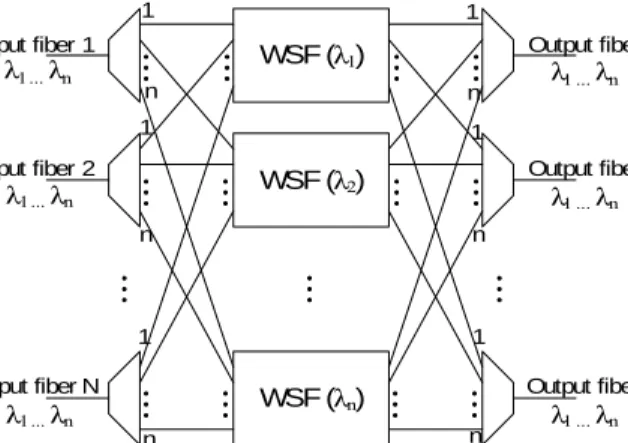
Fig. 2. The typical architecture of a switching node, consisting of demulti-plexers, wavelength switching fabric and multiplexers.
Out-of-band crosstalk In-band crosstalk a
)
b
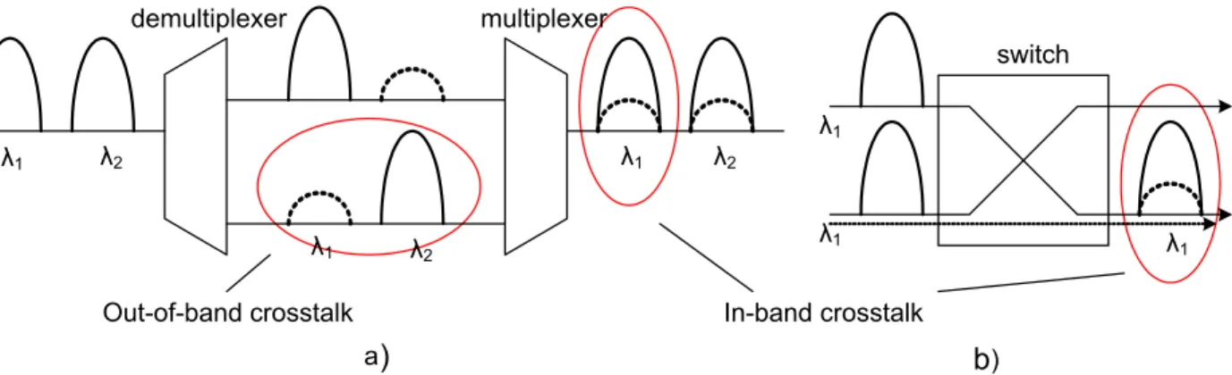
) demultiplexer multiplexer switch λ1 λ1 λ1 λ1 λ1 λ1 λ2 λ2 λ2Fig. 3. Optical multiplexer/demultiplexer (a) and optical switch (b) as sources of out-of-band and in-band crosstalk.
control solve this problem by monitoring the power levels in different ways and keeping the output power per channel constant, regardless of the input power. In such a network, high-power signals could not propagate. However, authors in [15] describe an attack which can affect even networks with automatic gain control. They refer to it as a low power QoS
attack. If an attacker attaches a splitter at the beginning of a
link, they are able to attenuate the power of the signal more than the amplifier is able to compensate for. This induced attenuation can significantly degrade the performance metrics of attacked lightpaths.
C. Optical Cross-Connects
Wavelength-selective optical cross-connects (OXC), also referred to as reconfigurable wavelength routing switches (WRS), are one of the key components in TONs. Their functions include lightpath provisioning, wavelength switch-ing, protection switching (rerouting connections), wavelength conversion and performance monitoring. They usually consist of demultiplexers, photonic switching fabric and multiplexers. A typical architecture of a switching node is shown in Fig. 2. When a signal enters an OXC on one of the incoming ports, first each of the wavelengths is demultiplexed onto its own fiber and then guided to the switching plane corresponding to that wavelength. After being directed to the wanted output port of the switch, it is guided to the optical multiplexer corresponding to that port, multiplexed with other wavelengths directed to that OXC output port and passed to the associated output fiber.
The main hazard to proper functioning of OXC nodes lies in crosstalk. In [16], two main mechanisms of crosstalk in OXC nodes are identified. The first originates in non-ideal response of the multiplexers and demultiplexers, while non-ideal switching gives rise to the second one. There are two types of crosstalk; out-of-band, which occurs among adjacent lightpaths at different wavelengths, and in-band, which occurs among lightpaths at the same wavelength.
Out-of-band crosstalk usually occurs in optical fibers,
es-pecially under high power conditions or long distances. It can also arise inside OXCs due to non-ideal demultiplexing, where one channel is selected and the others are not perfectly rejected
(Fig. 3a). Optical switches can also be a source of out-of-band crosstalk, which arises due to imperfect isolation of different output ports.
In-band crosstalk is, however, much more influential and
hazardous than out-of-band crosstalk. Namely, since the dam-aging signal is on the same wavelength as the legitimate signal, optical filters cannot filter it out, nor can it be removed by demultiplexers. Both multiplexers/demultiplexers and optical switches can be sources of in-band crosstalk, as shown in Fig. 3. Namely, when demultiplexers separate signals on different wavelengths, a small portion of each signal leaks onto ports reserved for signals on other wavelengths. When, after switching, different wavelengths are multiplexed back onto the same output fiber, small portions of one wavelength that had leaked onto other wavelengths will leak back onto the common fiber. Because of that, the signal on one wavelength will have crosstalk originating from its very own components carrying the same information, but suffering from different delays and phase shifts (Fig. 3a).
Optical switches are another source of in-band crosstalk (Fig. 3b). Namely, switch ports are not perfectly isolated from each other, so components of different signals transmitted on the same wavelength leak and interfere with each other. This means that each channel that crosses through an optical switch mixes with crosstalk leakage from signals on the same wavelength. An extensive study of crosstalk’s deleterious effect to signal quality and the system requirements it imposes can be found in [17].
In-band crosstalk inherent to optical switches can be used
for tapping. For example, if there are unused ports at the
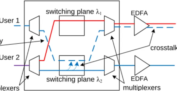
output of a switch to which a tapper gains access, they can analyze traffic and gain information carried at other signals on the same wavelength. This can be prevented by individually amplifying only signals which are registered with the network management system, which means that the crosstalk would not be amplified. However, an attacker can still request a legitimate data channel and then not send any information over it, but use it to tap other signals at the same wavelength. This kind of an attack is shown in Fig. 4.
User 1 User 2 switching plane λ1 switching plane λ2 demultiplexers multiplexers empty call crosstalk EDFA EDFA
Fig. 4. An example of tapping attack exploiting in-band crosstalk in a wavelength-selective switch.
suffer from significant levels of crosstalk of -20 dB (e.g. acousto-optical switches) to -30 dB (most other types) [10]. Even though these values are low enough to ensure proper communication, they allow for several types of attacks, aimed at service disruption or tapping. If an attacker injects a high-powered signal, its components will leak onto adjacent channels on the same wavelength, impairing the quality of the transmission on those signals, as shown in Fig. 5. Jamming attacks exploiting in-band crosstalk in switches have some of the highest damage capabilities among all attacks described above [11].
If the attacking signal is strong enough, it is possible that enough power is transferred onto adjacent channels inside their common switch, for them to gain attacking possibilities [11]. In this way, the attacked signal becomes an attacker, and attack propagates through the network, affecting signals which share no physical components with the signal which the attack originated from. This type of attack is shown in Fig. 6. Via in-band crosstalk in switches, the attacker does not affect only user 1’s legitimate signal, but the attack propagates to users 2 and 3, which share no common physical components with the original attacker.
This type of an attack is particularly hazardous to the proper network functioning, since the nature of its propagation makes it very difficult to localize the original source of the attack.
A study of the vulnerability of different node architectures to various attacks and faults, including in-band jamming causing crosstalk can be found in [18]. They describe various optical switch architectures commonly used in transparent optical networks. Optical cross-connects (OXCs), the main components of transparent mesh networks, can be realized us-ing broadcast & select (B&S) and wavelength-selective (WS) architectures. The study indicates that both implementations exhibit significant in-band crosstalk effects even under normal operating conditions, i.e., with no high-powered attacking signal. Somewhat lower in-band jamming vulnerability was found in WS architectures which employ (de)multiplexers with better port isolation.
Besides the in-band crosstalk vulnerability of the nodes themselves, the propagation of crosstalk attacks also depends on the physical and virtual topologies. A study of the impact of various physical and network-layer topologies on resilience under in-band crosstalk attacks assuming only direct attacks
switching plane λ1 switching plane λ2 demultiplexers multiplexers intra-channel crosstalk malicious channel legitimate users' signals
Fig. 5. An example of jamming attack causing in-band crosstalk in an optical switch.
from the original attacker can be found in [19]. Under the as-sumption of a fully connected virtual topology, fully-connected mesh, star and ring physical topologies are shown to be the least resilient to crosstalk attacks.
V. ATTACK ANDFAULTMANAGEMENT
In general, attack and fault management consists of preven-tion, detection and reaction (i.e. restoration of affected connec-tions) mechanisms [14]. Existing prevention techniques can be divided into hardware measures, transmission schemes and protocol/architecture design [10]. Hardware measures include adjusting the existing network equipment to new security de-mands or adding supplementary components, thus, increasing the overall cost of the network. Prevention via transmission schemes includes modulation or coding techniques, as well as limiting the signal bandwidth and power. Network architecture or protocols may also be designed to adapt to the changing security states of certain links and nodes in the network. Potential trade-offs of this technique include an increase in the length of certain routes or the number of used wavelengths.
Most approaches considering crosstalk attacks proposed in the literature deal with the consequences after they occur. The risk of losing and/or corrupting large amounts of data, as well as the difficulties in monitoring due to network transparency, call for sophisticated algorithms for precise localization of attacks. This is especially true if such attacks can propagate among different lightpaths, as is the case with jamming attacks causing in-band crosstalk. Several frameworks for fault localization in TONs have been proposed in [13], [14], [20] and [21], although a generalized approach has not yet
λ1 λ1 λ1 Attacker user 1 user 2 user 3 switch A switch B switch C IN-BAND CROSSTALK user 1 user 2 user 1 user 2 user 3 λ1 λ1 λ1 λ1
Fig. 6. In-band crosstalk attack propagation. The attacker can affect User 2’s and User 3’s signal even though they do not share any common physical components.
been established. The main reasons for this are the fact that very little is currently understood concerning performance monitoring in TONs [20], as well as the fact that the fault detection and localization methods design highly depends on the specific physical layer details [16].
Approaches in [11], [16] and [22] focus on monitoring and localization of in-band crosstalk attacks in particular. A distributed algorithm is proposed in [16] which deals with multiple in-band crosstalk attack localization and identifica-tion, but requires monitoring information for every established lightpath on the input and output sides of each OXC, raising scalability issues.
Monitoring difficulties, the nature of attack propagation in transparent optical networks, and large amounts of data they can severely affect, create the need to consider the possibilities of physical-layer attacks and try to minimize their impact already in the network planning phase. The concept of preventive, attack-aware RWA was recently proposed in [23]. The authors formulate the routing sub-problem of RWA as an integer linear program with the objective of decreasing the potential damage of jamming attacks causing out-of-band crosstalk in fibers and gain competition in optical amplifiers. A tabu search heuristic was proposed to cover larger network instances.
VI. CONCLUSION
The vulnerabilities of optical network fundamental physical components, as well as the attack techniques that exploit them combined with the transparency property of emerging all-optical networks demand new, specific ways of attack detec-tion, localization and network restoration. Besides upgrading existing ways of dealing with network failures and attacks and developing new ones, significant attention should be paid to prevention mechanisms, by taking physical layer impairments and attacks that exploit them into consideration already in the network planning phase. This approach, i.e., prevention-oriented network planning is a new concept which may play a significant role in increasing the all-optical network security in an economically more viable way.
REFERENCES
[1] N. Skorin-Kapov, “Routing and Wavelength Assignment in Optical Networks using Bin Packing Based Algorithms,” European Journal of Operational Research,vol. 177, no. 2, pp.1167–1179, March 2007. [2] J. S. Choi, N. Golmie, F. Lapeyrere, F. Mouveaux and D. Su, “A
Func-tional Classification of Routing and Wavelength Assignment Schemes in DWDM Networks: Static Case,” in Proc. of the 7th International Conference on Optical Communications and Networks, (OPNET), pp. 1109–1115, January 2000.
[3] A. Narula-Tam, P. J. Lin and E. Modiano, “Efficient Routing and Wavelength Assignment for Reconfigurable WDM Networks,” IEEE Journal on Selected Areas in Communications,vol. 20, no. 1, pp 75– 88, January 2002.
[4] H. Zang, J. P. Jue and B. Mukherjee, “A Review of Routing and Wave-length Assignment Approaches for WaveWave-length-Routed Optical WDM Networks,”Optical Networks Magazine,vol. 1, pp. 47–60, January 2000. [5] I. Chlamtac, A. Ganz and G. Karmi, “Lightpath communications: an approach to high-bandwidth optical WANs,” IEEE Transactions on Communications,vol. 40, pp. 1171–1182, 1992.
[6] R. Ramaswami and K. N. Sivarajan, “Optical Networks: A Practical Perspective,” 2nd edition, R. Adams, Ed., San Diego: Academic Press, 2002, pp. 437–488.
[7] T. Song, H. Zhang, Y. Guo and X. Zheng, “Statistical Study of Crosstalk Accumulation in WDM Optical Network Using Different RWA,”Optics Communication202, pp. 131–138, 2002.
[8] S. Azodomolky, M. Klinkowski, E. Marin, D. Careglio, J. Sol´e Pareta and I. Tomkos, “A survey on physical layer impairments aware routing and wavelength assignemnt algorithms in optical networks,” Computer Net-works: The International Journal of Computer and Telecommunications Networking,vol. 53, no. 7, p. 926–944, May 2009.
[9] C. C. Saradhi and S. Subramaniam, “Physical Layer Impairment Aware Routing (PLIAR) in WDM Optical Networks: Issues and Challenges,” IEEE Communications Surveys & Tutorials,vol. 11, no. 4, pp. 109–130, 4th quarter 2009.
[10] M. M´edard, D. Marquis, R. A. Barry and S. G. Finn, “Security Issues in All-Optical Networks”,IEEE Network Magazine, vol. 11, no. 3, pp. 42–48, May 1997.
[11] T. Wu and A. K. Somani, “Cross-Talk Attack Monitoring and Localiza-tion in All-Optical Networks,”IEEE/ACM Transactions on Networking 13, pp. 1390-1401 (2005).
[12] M. M´edard, D. Marquis, S. R. Chinn, “Attack Detection Methods for All-Optical Networks”, in in Proc. of Network and Distributed Systems Security Symposium,Session 3, paper 2, San Diego, California, 1998. [13] J. K. Patel, S. U. Kim, D. H. Su, S. Subramaniam and H.-A. Choi, “A
Framework for Managing Faults and Attacks in WDM Optical Networks,” Proc. of the DARPA Information Survivability Conference and Exposition, Anaheim, California 2001.
[14] C. Mas, I. Tomkos and O. K. Tonguz, “Failure Location Algorithm for Transparent Optical Networks,”,IEEE Journal on Selected Areas in Communication, vol. 23, no. 8, pp. 1508–1519, August 2005.
[15] T. Deng and S. Subramaniam, “Covert low-power QoS attack in all-optical wavelength routed network,” in Proc. of IEEE Global Telecom-munications Conference (GLOBECOM)vol. 3, pp. 1948-1952, 2004. [16] R. Rejeb, M. S. Leeson and R. J. Green, “Multiple Attack Localization
and Identification in All-optical Networks,” Optical Switching and Networking3, pp. 41–49, 2006.
[17] T. Y. Chai, T. H. Cheng, Y. Ye and Q. Liu, “Inband Crosstalk Analysis of Optical Cross-Connect Architectures, ” Journal of Lightwave Tech-nologies, Vol. 23, No. 2 pp. 688–701, February 2005.
[18] P. Gil Arbu´es, C. Mas Machuca and A. Tzanakaki, “Comparative study of existing OADM and OXC architectures and technologies from the failure behavior perspective,” Journal of Optical Networking,vol. 6, no. 2, pp. 123–133, February 2007.
[19] C. Liu and C. Ji, “Resilience of All-Optical Network Architectures under In-band Crosstalk Attacks: A Probabilistic Graphical Model Approach,” IEEE Journal on Selected Areas of Communication,vol. 25, Issue 3, pp. 2–17, 2007.
[20] R. Rejeb, M. S. Leeson and R. J. Green, “Fault and Attack Management in All-Optical Networks,”IEEE Communications Magazine, vol. 44, no. 11, pp. 79–86, November 2006.
[21] R. Bergman, M. M´edard and S. Chan, “Distributed Algorithms for Attack Localization in All-Optical Networks,” inNetwork and Distributed Systems Symposium, San Diego, California, March 1998.
[22] A. Jedidi and M. Abid, “Optimal Crosstalk Monitoring and Identifi-cation Method,” IFIP International Conference on Wireless and Optical Communication Networks (WOCN’09), pp. 1–5, 2009.
[23] N. Skorin-Kapov, J. Chen, L. Wosinska, “A New Approach to Optical Networks Security: Attack-Aware Routing and Wavelength Assignment,” IEEE/ACM Transactions on Networking, vol. 18, no. 3, pp. 750–760, 2010.