10FTM08
AGMA Technical Paper
Calculation of Load
Distribution in Planetary
Gears for an Effective
Gear Design Process
By Dr.-Ing. T. Schulze and
Dipl.-Ing. C. Hartmann-Gerlach,
DriveConcepts GmbH
Calculation of Load Distribution in Planetary Gears for an
Effective Gear Design Process
Dr.-Ing. Tobias Schulze and Dipl.-Ing. Christian Hartmann-Gerlach, DriveConcepts
GmbH and Prof. Dr.-Ing. Berthold Schlecht, Technical University of Dresden
[The statements and opinions contained herein are those of the author and should not be construed as an official action or opinion of the American Gear Manufacturers Association.]
Abstract
The design of gears - especially planetary gears - can just be carried out by the consideration of influences of the whole drive train and the analysis of all relevant machine elements. In this case the gear is more than the sum of its machine elements. Relevant interactions need to be considered under real conditions. The standardized calculations are decisive for the safe dimensioning of the machine elements with the consideration of realistic load assumptions. But they need to be completed by extended analysis of load distribution, flank pressure, root stress, transmission error and contact temperature.
Copyright2010
American Gear Manufacturers Association 500 Montgomery Street, Suite 350
Alexandria, Virginia, 22314 October 2010
Calculation of Load Distribution in Planetary Gears
for an Effective Gear Design Process
Dr.--Ing. Tobias Schulze and Dipl.--Ing. Christian Hartmann--Gerlach, DriveConcepts
GmbH and Prof. Dr.--Ing. Berthold Schlecht, Technical University of Dresden
Introduction
For the dimensioning of highly stressed toothings the analysis of load distribution and the definition of tooth flank modifications belongs to the principal tasks. Similar problems appear at the evaluation of toothing damages and failure modes of whole gears. Although there are a large number of standards for the calculation of spur gears, ISO 6336. It is necessary to have special and powerful calculation software which is reflecting the force--deformation--relation for every point of the contact area more precisely. The cause is the divergence from the conjugated toothings at gear wheels of spur and planetary gears. Often the flanks are mod-ified in height and width direction. With these modi-fications the load--dependent deformations of the toothing and the surroundings as well as toothing errors, position errors of the housing boreholes and bearing clearance can be compensated. Also the gear noise as well as the load capacity is influenced in a positive way.
For the determination of the load distribution in planetary gear stages the deformation analysis is a more complex task as for spur gear stages. The deformation of the wheel body as well as the adja-cent structures and the planet carrier can’t be calcu-lated efficiency in an analytical way. They need to be investigated with FE calculations or extended model approaches.
With a detailed load distribution analyses software /7/ all necessary calculations for the load analysis of planetary gears are united. The relevant deforma-tions are determined with automatically generated FE meshes of the gear wheels and planet carrier and are used for the load distribution calculation after wards. The software MDESIGN LVRplanet allows the load distribution calculation of planetary stages with spur, helical and double helical gear wheels. Therefore analytical functions for the con-tact area are in use. As result you can see the fast computing time despite of the high--resolution rough
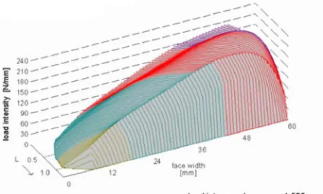
discretization of the used model. The load, pressure, root stress distribution and width load factor can be interpreted, Figure 1.
Figure 1. Bad load distribution on flank
Furthermore the program is giving suggestions how to modify the flanks for a well--balanced load distribution, see Figure 2.
Figure 2. Good load distribution on flank
To solve all this calculation tasks in an efficient way it is necessary to install calculation software. To reduce the necessary inputs to a minimum it is indis-pensable to have a high degree of connections between the single calculation modules (gear design, calculation accord. Standards, load distribution analysis). In the background the task is efficiently solved with scientific established calculation kernels and uniform interfaces. So a
4 fast and secure concept, dimensioning and calculation of the machine element, the gear and the whole drive train are possible. There is the pos-sibility to optimize toothing, shafts, bearings and bolts with use of real load assumption. Using this calculation software already at an early point of the product life cycle, PLC, you can get secure state-ments of your finish product without manufacturing prototypes. This calculation method can’t totally replace the measuring campaign and test runs but unnecessary iterations can be switched off.
Applications of large gearboxes
The gearboxes described in this article are mostly used in heavy drive trains, special purpose machinery and in wind power plants, Figure 3. The characteristic of all these operating areas are turbulent and unsteady loads, uncertain boundary conditions and in some cases very high load peaks.
Figure 3. Application – wind power plant
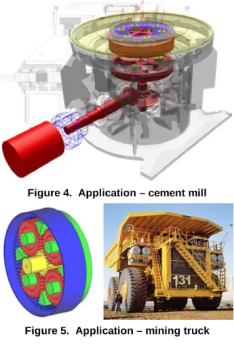
For wind turbines the wind, the start-- and stop procedure are the most important dynamic input parameter – and also the biggest unsureness for load conditions. By the mills there is the same fact in terms of flow of material, Figure 4.
A very special case study is the drive train of big mining trucks with high power output up to 700 kW and cyclic loads for transportation in surface min-ing’s, Figure 5.
In all of these operation areas there are high requirements to design, optimization and calculation of drive trains and especially gearboxes.
Figure 4. Application – cement mill
Figure 5. Application – mining truck
Another example of a large gearbox with high power output and cyclic loads is the foundry crane in Figure 6 for transportation of melted mass.
Basics of load distribution
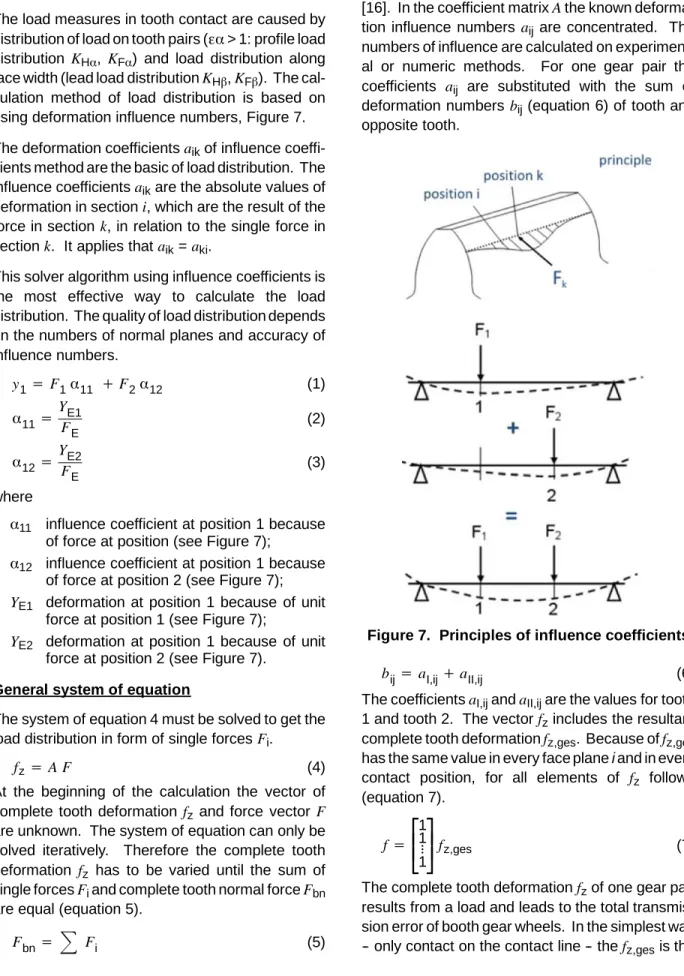
The load measures in tooth contact are caused by distribution of load on tooth pairs (εα> 1: profile load distribution KHα, KFα) and load distribution along face width (lead load distributionKHβ,KFβ). The cal-culation method of load distribution is based on using deformation influence numbers, Figure 7. The deformation coefficientsaikof influence coeffi-cients method are the basic of load distribution. The influence coefficientsaikare the absolute values of deformation in sectioni, which are the result of the force in sectionk, in relation to the single force in sectionk. It applies thataik=aki.
This solver algorithm using influence coefficients is the most effective way to calculate the load distribution. The quality of load distribution depends on the numbers of normal planes and accuracy of influence numbers. y1=F1α11 +F2α12 (1) α11=YE1 FE (2) α12=YE2 FE (3) where
α11 influence coefficient at position 1 because of force at position (see Figure 7);
α12 influence coefficient at position 1 because of force at position 2 (see Figure 7);
YE1 deformation at position 1 because of unit force at position 1 (see Figure 7);
YE2 deformation at position 1 because of unit force at position 2 (see Figure 7).
General system of equation
The system of equation 4 must be solved to get the load distribution in form of single forcesFi.
fz=A F (4)
At the beginning of the calculation the vector of complete tooth deformationfz and force vector F are unknown. The system of equation can only be solved iteratively. Therefore the complete tooth deformation fz has to be varied until the sum of single forcesFiand complete tooth normal forceFbn are equal (equation 5).
Fbn=
Fi (5)The calculation ofFbnis done with equations from [16]. In the coefficient matrixAthe known deforma-tion influence numbersaij are concentrated. The numbers of influence are calculated on experiment-al or numeric methods. For one gear pair the coefficients aij are substituted with the sum of deformation numbersbij(equation 6) of tooth and opposite tooth.
Figure 7. Principles of influence coefficients
bij=aI,ij+aII,ij (6) The coefficientsaI,ijandaII,ijare the values for tooth 1 and tooth 2. The vectorfzincludes the resultant complete tooth deformationfz,ges. Because offz,ges has the same value in every face plane i and in every contact position, for all elements of fz follows (equation 7). f=
⎪⎡⎣
11 ⋮ 1⎪⎤⎦
fz,ges (7)The complete tooth deformationfzof one gear pair results from a load and leads to the total transmis-sion error of booth gear wheels. In the simplest way -- only contact on the contact line -- thefz,gesis the
6 result of elastic tooth deformationfzI,iandfzII,ifrom pinion and gear (equation 8).
fz,i=fzI,i+fzII,i=fz,ges=const. (8) In the simplest way the contact line deviation consists of the existing deviation of the designed flank and eventually added modifications. The contact line deviation is calculated for one position of contact and unencumbered load case, so it is a constant initial value for solving the complete system of equation. The current values are combined in vectorfk, the contact line deviation. In the advanced form all existing deformations and displacements, i.e. deflection of shaft, bearing clearance, excepting deformation of numbers of influences, are considered in vector fk. These deformations and displacements can be calculated independently from load distribution. If an additional contact line deviationfkis superposed on elastic deformations, equation 8 must be changed to equation 9.
fz,i=fzI,i+fzII,i+fk,i−gi=fz,ges=const. (9) The resultant deviation of the gear pair after elastic deformation is expressed with the part gi. The elast-ic tooth deformationsfzI, iandfzII, iare replaced in the system with force vectorFand coefficient matrixA. So an enlarged system of equation 10 is built.
fz,ges=A F+fk−g (10) When the result of the system of equation is a negative single forceFi, it means that this section doesn’t contact under complete tooth force and a resultant flank deviation giexists. The system of equation is compressed and solved again after deletion of row i and column for every negative sec-tion force. The operasec-tion is repeated until no negat-ive single forces exist. After deletion the system of equation 11 remains. One row of the system of equation for one gear pair can be expressed (equation 12) according to Figure 7.
A F=fz,ges−fk (11)
n k=1
aikFk
=fz,ges−fki (12) Enlarged system of equation: If more results of Hohrein/Senf [14, 15] are used, the system of equation 13 forFandfzcan be solved directly.⎪⎪
⎪
⎡
⎣
⎪
⎡
⎣
A⎪
⎤
⎦
−1 −1 ⋮ −1 1 1 ⋅⋅⋅ 0⎪⎪
⎪
⎤
⎦
⎪⎪⎪
⎪
⎡
⎣
F1 F2 3. Fn fz,ges⎪⎪⎪
⎪
⎤
⎦
=⎪⎪
⎡
⎣
⎪⎡⎣
−fk⎪⎤⎦
Fbn⎪⎪
⎤
⎦
(13)The matrix of deformation numbers of influenceA
consists of the matrix of Hertzian deformationAH and the matrix of the resultant tooth deformationAZ (equation 14).
A=AH+AZ (14) A directly solving of the system of equation 13, respectively the solving algorithm, is only possible by linear interrelations between load and deforma-tion. Non linear variables (i.e., Hertzian pressure) are linearized or considered in the system of equation by iterative operations. To include the load depending Hertzian influence on deformation exactly, the algorithm of load distribution has to be done in one position of contact several times. After every step of iteration the Hertzian stiffness is adapted to the actual load distribution. The iterative calculation is also necessary to involve deformation of surrounding from resilience of surrounding to achieve a correct load distribution. As aforemen-tioned, the negative single forces Fi because of flank deviation are deleted by compressing the system of equation.
If at the same time more tooth pairsnare in contact, the system of equation 13 is enlarged and the coeffi-cient matrixAp(equation 15) of one tooth pairpis seen as matrix of discontinuity. If in this equation also the null terminated matrices are reserved the opposite influence (cross influence) of neighboring tooth pairs can be shown. When using solid wheels the cross influence is disregarded and the teeth are uncoupled. A=
⎪⎪
⎡
⎣
A1 0 0 ⋮ ⋮ ⋮ ⋮ 0 Ap 0 0 0 An⎪⎪
⎤
⎦
(15) Flank modificationsThe general way to use flank modifications is described by the following 3 steps:
1. Load depending deformations should be influenced by design arrangements in this way that they are reduced or maybe compensated.
2. The residual linear variable part of contact line deviation depending on load, thermic and centri-fugal force has to be compensated by helical flank modification.
3. The contact line deviation, which balances around expected value 0, caused by measure-ment deviation of gears, deviation of gear wobbling and other raisings of load on the face side has to be reduced by an additional lead crowning.
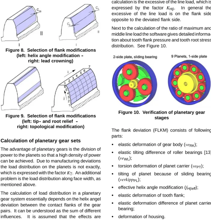
Figure 8 and Figure 9 show some possible modifications on the tooth flank.
Figure 8. Selection of flank modifications (left: helix angle modification
--right: lead crowning)
Figure 9. Selection of flank modifications (left: tip and root relief
--right: topological modification)
Calculation of planetary gear sets
The advantage of planetary gears is the division of power to the planets so that a high density of power can be achieved. Due to manufacturing deviations the load distribution on the planets is not exactly, which is expressed with the factorKγ. An additional problem is the load distribution along face width, as mentioned above.
The calculation of load distribution in a planetary gear system essentially depends on the helix angel deviation between the contact flanks of the gear pairs. It can be understood as the sum of different influences. It is assumed that the effects are
overlying independently, the sum of contact line deviation can be calculated with the single deviations. The calculation of single displacements and deformations of all gear box bodies – especially the planet carrier, the coupling of ring gear and gear wheel bodies and the deformation of teeth – is in planetary gearboxes more complex than in spur gearboxes.
To determine the load distribution the flank deviation for the tooth contact sun/planet and the tooth contact planet/ring gear is calculated by the new software MDESIGN LVRplanet. The result of the calculation is the excessive of the line load, which is expressed by the factor KHβ. In general the excessive of the line load is on the flank side opposite to the deviated flank side.
Next to the calculation of the ratio of maximum and middle line load the software gives detailed informa-tion about tooth flank pressure and tooth root stress distribution. See Figure 10.
Figure 10. Verification of planetary gear stages
The flank deviation (FLKM) consists of following parts:
S elastic deformation of gear body (veRK); S elastic tilting difference of roller bearings [13]
(veWL);
S torsion deformation of planet carrier (vePT); S tilting of planet because of sliding bearing
(verkippPL);
S effective helix angle modification (fHβeff); S elastic deformation of tooth flank;
S elastic deformation difference of planet carrier bearing;
8 The helix angle deviation for tooth contact sun/ planet is calculated by equation 16.
FLKM1∕2=ve1+ve2
1∕2+veWL1∕2+vePT1∕2 +verkippPL1∕2+fHβeff1∕2
(16) The helix angle deviation for tooth contact planet/ ring gear is calculated by equation 17.
FLKM2∕3=ve2
2∕3+ve3+veWL2∕3+vePT2∕3
+verkippPL2∕3+fHβeff2∕3
(17) where
ve1 deformation difference of sun;
ve2 deformation difference of planet;
ve3 deformation difference of ring gear. The deformation is calculated by the FE--method and after wards it is added to the flank deviation. All parts of the helix angle deviation have to be added as values normal to the flank.
The database of the calculation is saved in XML--Format. With this a structured depositing of design--, modifications--, deviation--, load-- and control data is possible. Furthermore the program has a project management which is based on a database to save projects, for standard examples and more calculation guidelines.
After input of all necessary parameters all data are checked, the design models are generated and the FE--models for the gears with coupling design and the planet carrier are created. Figure 11 shows some design variants of planet carriers.
Figure 11. Design variants of planet carrier
For an efficient calculation it is necessary and reasonable to use software. DriveConcepts GmbH develops software solutions for drive technology, which is characterized by clear and intuitive handling of all data.
In the background academic established calculation kernels and consistent structured interfaces help to solve the actual task efficiently.
Gearbox design
Especially for design concepts of planetary and spur gearboxes the newest development of Drive-Concepts GmbH the product MDESIGN gearbox is established, see Figure 12. This calculation software gives complete product information in the early phase of product life cycle, PLC. The calculation can’t replace measurements and test drives, but iteration steps can be reduced economically.
Figure 12. Design and optimization of planetary gear boxes
The software allows an intuitive and easy handling in the design process of whole gearboxes from the dimensioning of the machine elements – shafts, bearings and toothings -- according to the actual standards. See Figure 13.
Figure 13. Gearbox model of a multi stage spur gear in the software MDESIGN gearbox
In a second step the consideration of CAD geometry data of housings will be possible. There-fore the software imports a standard geometry format, generate Finite Element models, calculate stiffness matrices for the housing and deliver this information to the design process of MDESIGN gearbox. See Figure 14.
Figure 14. Selection of interfaces between bearing and housing
Case study
The example of a wind turbine with 2000 kW output power should show the consequences of different flank modifications with constant load. See Figure 15.
Figure 15. Case study – wind power plant
The main gearbox consists of three gear stages (helical gearing). The detailed parameters of the 1st planetary gear stage are listed in Table 1. Additional parameters (e.g., the bearing characteristics, carrier pin tolerances) are not shown, but they had
to consider for realistic determination of load distribution. See Table 1.
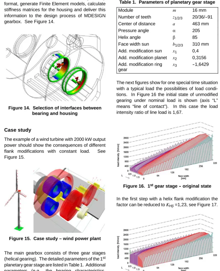
Table 1. Parameters of planetary gear stage
Module m 16 mm
Number of teeth z1/2/3 20/36/--91 Center of distance a 463 mm
Pressure angle α 205
Helix angle β 85
Face width sun b1/2/3 310 mm Add. modification sun x1 0,4 Add. modification planet x2 0,3156 Add. modification ring
gear
x3 --1,6429
The next figures show for one special time situation with a typical load the possibilities of load condi-tions. In Figure 16 the initial state of unmodified gearing under nominal load is shown (axis “L” means “line of contact”). In this case the load intensity ratio of line load is 1,67.
Figure 16. 1stgear stage -- original state
In the first step with a helix flank modification the factor can be reduced toKHβ=1,23, see Figure 17.
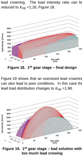
10 The rest of unbalanced distribution along the face width, which comes from planet carrier torsion deformation, can be compensated with an optimal lead crowning. The load intensity ratio can be reduced toKHβ=1,16, Figure 18.
Figure 18. 1stgear stage – final design
Figure 19 shows that an oversized lead crowning can also lead to poor conditions. In this case the lead load distribution changes toKHβ=1,98.
Figure 19. 1stgear stage – bad solution with
too much lead crowing
The example shows the must oft the right dimension of used modifications. If these are right the lead load distribution KHβcan be reduced from 1,67 to 1,16. But with unfavorable modifications the opposite will be achieved.
The case study shows many advantages of integrated software, like MDESIGN LVRplanet, to develop gearboxes.
References
1. Börner, J. Senf, M.: Verzahnungsbeans-pruchung im Eingriffsfeld – effektiv berechnet. Antriebstechnik 1, 1995
2. Börner, J.: Very efficient calculation of the load distribution on external gear sets – the method and application of the program LVR. Interna-tional ASME Conference, San Diego, 1996 3. Hartmann--Gerlach, Christian:
Verformungsan-alyse von Planetenträgern unter Verwendung der Finiten Elemente Methode. Internal draft, TU Dresden 2008
4. ISO 6336:2006 Calculation of load capacity of spur and helical gears
5. Linke, H.: Beitrag zur Ermittlung der Zahn-flanken-- und Zahnfuβtragfähigkeit unter Ber-ücksichtigung der Abweichungen geomet-rischer Gröβen, Deformation der Getriebeteile und der Werkstoffkennwerte. Habilitationss-chrift TU Dresden, 1978
6. MDESIGN LVR 2010, software for load distribu-tion of multi stage spur-- and helical gears. DriveConcepts GmbH, 2010
7. MDESIGN LVRplanet 2010, software for load distribution of planetary gear stages. Drive-Concepts GmbH, 2010
8. MDESIGN gearbox 2010, design and calcula-tion software for multi stage gearboxes. Drive-Concepts GmbH, 2010
9. Schlecht, B. Senf, M.; Schulze, T.: Beans-pruchungsanalyse bei Stirnradgetrieben. An-triebsstränge in Windenergieanlagen -- Haus der Technik e.V., Essen, o9./1o. März 2010 10. Schulze, Tobias: Ganzheitliche dynamische
Antriebsstrangsbetrachtung von Windener-gieanlagen. Sierke Verlag 2008, PhD thesis TU Dresden
11. Schulze, Tobias: Getriebeberechnung nach ak-tuellen wissenschaftlichen Erkenntnissen, Vor-trag anlässlich des Dresdner Maschinenele-mente DMK2007 in Dresden, DriveConcepts GmbH, 2007
12. Schulze, Tobias: Load distribution in planetary gears under consideration all relevant influ-ences. JSME International Conference on Mo-tion and Power Transmissions May 13--15, 2009, Matsushima Isles Resort, Japan 13. Schulze, Tobias: Load distribution in planetary
gears. Danish gear society “Gearteknisk In-teresseGruppe” 11th february 2010 at SDU in Odense, Denmark
14. Wiche, E.: Radiale Federung von Wälzlagern bei beliebiger Lagerluft. Konstruktion, Berlin 19(1967)5
15. Hohrein, A.; Senf, M.: Untersuchungen zur Last-- und Spannungsverteilung an
schrägverzahnten Stirnrädern. Diss. TU Dresden, 1978
16. Linke, H.: Stirnradverzahnung – Berechnung, Werkstoffe, Fertigung. München, Wien: Hanser, 1996