Nonlinear Autoregressive Moving Average-L2
Model Based Adaptive Control of Nonlinear Arm Nerve
Simulator System
Mustefa JibrilDepartment of Electrical & Computer Engineering, Dire Dawa Institute of Technology, Dire Dawa, Ethiopia
Dr.Prashanth Alluvada
Faculty of Electrical & Computer Engineering, Jimma Institute of Technology, Jimma, Ethiopia
Abstract
This paper considers the trouble of the usage of approximate strategies for realizing the neural controllers for nonlinear SISO systems. In this paper, we introduce the nonlinear autoregressive moving average (NARMA-L2) model which might be approximations to the NARMA model. The nonlinear autoregressive moving average (NARMA-L2) model is an precise illustration of the input–output behavior of finite-dimensional nonlinear discrete time dynamical systems in a neighborhood of the equilibrium state. However, it isn't always handy for purposes of neural networks due to its nonlinear dependence on the manipulate input. In this paper, nerves system based arm position sensor device is used to degree the precise arm function for nerve patients the use of the proposed systems. In this paper, neural network controller is designed with NARMA-L2 model, neural network controller is designed with NARMA-L2 model system identification based predictive controller and neural network controller is designed with NARMA-L2 model based model reference adaptive control system. Hence, quite regularly, approximate techniques are used for figuring out the neural controllers to conquer computational complexity. Comparison were made among the neural network controller with NARMA-L2 model, neural network controller with NARMA-L2 model system identification based predictive controller and neural network controller with NARMA-L2 model reference based adaptive control for the preferred input arm function (step, sine wave and random signals). The comparative simulation result shows the effectiveness of the system with a neural network controller with NARMA-L2 model based model reference adaptive control system.
Index Terms: Nonlinear autoregressive moving average, neural network, Model reference adaptive control, Predictive controller
DOI: 10.7176/ISDE/11-2-02
Publication date:March 31st 2020
I. INTRODUCTION
The neural network pattern tins be used in dominion strategies that require a global creation of the diagram forward or inverse dynamics, and these form are available in the example of neural networks, which have been trained using neural based design discovery techniques. The generalized teaching dresser attempts to crops the inverse of a fortification over the entire kingdom crack using off-line training while in the specialized configuration the convention is on-line and uses incorrectness back dispersal through the movement to learn the protocol inverse liveliness over a small operating region. The global firmness of the closed-loop response design is guaranteed provided the arrangement of the robot-manipulator action phrase is exact. Generalization of the director over the desired path breach has been established using an on-line weight education scheme. The advantage of a neuron-adaptive hybrids mastery scheme is the high accuracy and computationally less intensive proficiency scheme.
II. SYSTEM DISCRIPTION
A. Nerves System Based Arm Position Sensor System Description
Nerves system based arm position sensor is a device which senses the electrical pulse signal of the nerve and compares the desired arm position and response arm position of the nerve defected arm. Nerves system based arm position sensor is a type of neuro modulation therapy in which electrodes are surfacely placed next to a selected peripheral nerve considered to be the source of nerve pain. One way of trying to control the arm position is that arises from peripheral nerves calls for a device that sends low levels of electricity to stimulate part(s) of the nerve. This electrical voltage is thought to interfere with how the nerve transmits the voltage impulse signals and response through arm motion.
2 2 2 1 d y t v t dy t dt s y t s dt
Wherey (t) Arm position output
v (t) Impulse voltage input
γ Arm position acceleration s Device sensitivity function
α Nerve transmission coefficient
β Nerve delay coefficient
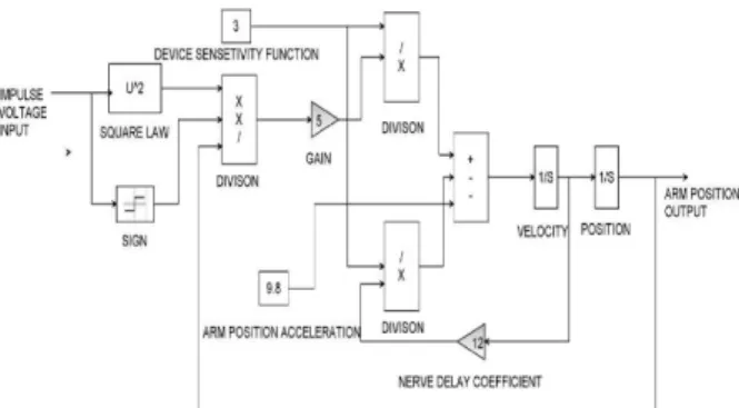
The block diagram of the nerves system based arm position sensor device is shown in Figure 1 bellow.
Fig. 1. Block diagram of the nerves system based arm position sensor device
B. Design of NARMA-L2 Neural Network Controller
The neuro controller described on this phase is cited through two different names: response linearization control and NARMA-L2 manipulate. It is known as comments linearization when the plant shape has a specific form (associate form). It is known as NARMA-L2 manipulate while the fortification mold may be approximated by using the same form. The vital principle of this type of control is to convert nonlinear design system into linear dynamics with the aid of canceling the nonlinearities. This phase starts off evolved with the aid of submitting the associate system form and presentation how you may use a neural community to become aware of this model. Then it describes how the identified neural network model may be used to broaden a controller.
1) Identification of the NARMA-L2 Model: The first step in the use of feedback linearization (or NARMA-L2)
manipulate is to identify the design to be controlled. You train a neural network to represent the forward dynamics of the system.
The first step is to pick out a styles association to use. One standard patterns this is used to symbolize fashionable discrete-time nonlinear system is the nonlinear autoregressive-moving average (NARMA) model:
, 1 ,...,
1 ,
, 1 ,....,
1
2y k d N y k y k y k n u k u k u k n Where u(k) is the system input, and y(k) is the
Where u(k) is the system input, and y(k) is the system output. For the identification section, you can teach a neural network to approximate the nonlinear function N. If you want the system output to follow some reference trajectory
y (k + d) = yr (k + d) the subsequent step is to expand a nonlinear controller of the form: , 1 ,..., 1 , r , 1 ,...., 1 3
u k G y k y k y k n y k d u k u k m
The trouble with the usage of this controller is that in case you need to teach a neural network to create the characteristic G to minimize mean square blunders, you need to apply dynamic returned propagation. This can be pretty sluggish. One answer is to apply approximate models to symbolize the system. The controller used on this section is based totally at the NARMA-L2 approximate model:
, 1 ,.., , 1 ,.., 1 , ˆ 4 1 , 1 ,.., 1 1 ,.., 1 y k y k y k y k y k n y k d f g u k y k n u k u k m u k u k m
This model is in associate shape, wherein the next controller input u(k) is not contained in the nonlinearity. The gain of this form is that you could resolve for the control input that causes the system output to comply with the reference y (k + d) = yr (k + d). The resulting
controller would have the form
, 1 ,..., 1 , 1 ,...., 1 5 , 1 ,..., 1 , 1 ,...., 1 r y k d f y k y k y k n u k u k n u k g y k y k y k n u k u k n
Using this equation immediately can motive awareness problems, due to the fact you ought to determine the control input u(k) primarily based on the output at the same time, y(k). So, rather, use the model
, 1 ,.., 1 , , 1 ,.., 1 6 1 ,.., 1 1 , 1 ,.., 1 y k y k y k n y k y k y y k d f g u k u k u k m k n u k u k m
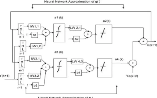
network representation
Fig. 2. The structure of a neural network representation. Using the NARMA-L2 model, you can obtain the controller
1 , 1 ,..., 1 , ,...., 1 7 , 1 ,..., 1 , ,...., 1 r y k d f y k y k y k n u k u k n u k g y k y k y k n u k u k n
Which is realizable for d ≥ 2. Figure 3 shows the block diagram of the NARMA-L2 controller.
Fig. 3. Block diagram of the NARMA-L2 controller
This controller can be implemented with the formerly diagnosed NARMA-L2 plant model, as shown in Figure 4 below.
Fig. 4. Previously identified NARMA-L2 plant model
C. Design of NARMA-L2 Model Controller Using SystemIdentification
The NARMA-L2 based neural network predictive controller makes use of a neural network model of a nonlinear plant to expect future plant performance. The controller then calculates the control input that will optimize plant performance over a targeted destiny time horizon. The first step in model predictive control is to determine the neural network plant model. Next, the plant model is utilized by the controller to predict future performance.
1) System Identification:
The first stage of model NARMAL2 based predictive controller is to train a neural network to symbolize the ahead dynamics of the plant. The prediction errors among the plant output and the neural network output is used as the neural network education signal. The method is shown in Figure 5 below:
Fig. 5. The process of training model predictive control
The neural network plant model uses preceding inputs and former plant outputs to be expecting destiny values of the plant output. The structure of the neural network plant model is given in Figure 6 bellow.
Fig. 6. The structure of the neural network plant model
2) Predictive Control:
The model predictive control technique is based totally on the receding horizon method. The neural network model predicts the plant reaction over a unique time horizon. The predictions are used by a numerical optimization software to decide the control signal that minimizes the following performance criterion over the required horizon
2 1 2 ' ' 2 m 1 ( ( ) y (- )) ( ( - -1) u (k+j 2))- 8 u N N r j N j J y k j k j u k j
Where N1, N2, and Nu define the horizons over which the tracking blunders and the manage increments are evaluated. The u´ variable is the tentative control signal, yr is the preferred response, and ym is the network model reaction. The cost determines the contribution that the sum of the squares of the control increments has on the performance index.
The following block diagram illustrates the model predictive control method. The controller consists of the neural network plant model and the optimization block. The optimization block determines the values of u´ that limit J, after which the top of the line u is input to the plant.
Fig. 7. Block diagram of the model predictive control process
D. Design of NARMA-L2 Model Controller Using AdaptiveControl
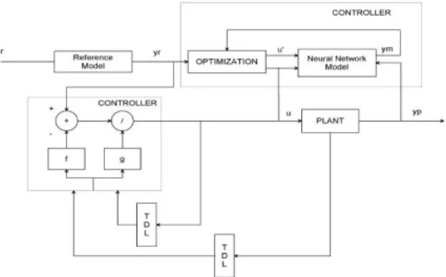
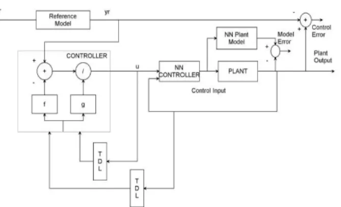
The NARMA-L2 based neural model reference adaptive control structure uses neural networks: a controller network and a plant model network, as shown in Figure 8 below. The plant model is identified first, and then the controller is trained in order that the plant output follows the reference model output.
Fig. 8. Block diagram of controller network and a plant model network
Figure 9 indicates the info of the neural network plant model and the neural network controller. Each network has two layers, and you can pick out the quantity of neurons to use within the hidden layers. There are three units of controller inputs:
• Delayed reference inputs • Delayed controller outputs • Delayed plant outputs
For each of those inputs, you can select the variety of delayed values to apply. Typically, the variety of delays increases with the order of the plant. There are two sets of inputs to the neural network plant model: Delayed controller outputs
• Delayed plant outputs
Fig. 9. The neural network plant model and the neural network controller
III. RESULT AND DISSCUSION
This chapter basically focuses on the comparison of neural network controller with NARMA-L2 model, neural network controller with NARMA-L2 model system identification based predictive controller and neural network controller with NARMA-L2 model based model reference adaptive control . These three systems input is the desired arm position and they generate impulse voltage signal to be given to the arm and the arm deliver arm output position. These three systems tested with step, sine wave and random desired arm position signal.
A. Comparison of the Proposed Controllers using step input signal
The Simulink model for the comparison of neural network controller with NARMA-L2 model, neural network controller with NARMA-L2 model system identification based predictive controller and neural network controller with NARMA-L2 model based model reference adaptive control using step input signal is shown in the Figure 10 bellow
Fig. 10. Step response Simulink model
The simulation output for the comparison of the neural network controller with NARMA-L2 model, neural network controller with NARMA-L2 model system identification based predictive controller and neural network controller with NARMA-L2 model based model reference adaptive control using step input signal is shown in the Figure 11 bellow.
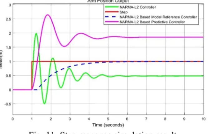
Fig. 11. Step response simulation result
The neural network controller with NARMA-L2 controller has a high percentage overshoot and since the step input signal is the desired arm position of the patient and the output of this controller has a steady state value of 0.5 m while the desired arm position is 1m. This show us that the neural network controller with NARMA-L2 controller does not feed enough nerve impulse voltage to the nerve of the arm. The neural network controller with NARMA-L2 model system identification based predictive controller has a bigger percentage overshoot and since the step input signal is the desired arm position of the patient and the output of this controller has a steady state value of 1.75 m while the desired arm position is 1m. This show us that the neural network controller with NARMA-L2 model system identification based predictive controller feed excess nerve impulse voltage to the nerve of the arm. The neural network controller with NARMAL2 model based model reference adaptive control has a no percentage overshoot and since the step input signal is the desired arm position of the patient and the output of this controller has the same steady state value of 1 m with the desired arm position. This show us that the neural network controller with NARMA-L2 model based model reference adaptive control gives the exact nerve impulse voltage to the nerve of the arm.
B. Comparison of the Proposed Controllers using Sine Wave Input Signal
The Simulink model for the comparison of neural network controller with NARMA-L2 model, neural network controller with NARMA-L2 model system identification based predictive controller and neural network controller with NARMA-L2 model based model reference adaptive control using sine wave input signal is shown in the Figure 12 bellow
Fig. 12. Sine wave response Simulink model
The simulation output for the comparison of the neural network controller with NARMA-L2 model, neural network controller with NARMA-L2 model system identification based predictive controller and neural network controller with NARMA-L2 model based model reference adaptive control using sine wave input signal is shown in the Figure 13 bellow
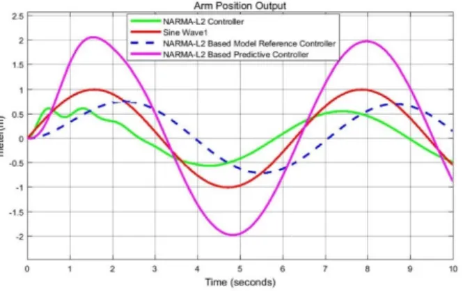
Fig. 13. Sine wave response simulation result
The neural network controller with NARMA-L2 controller sine wave input signal is the desired arm position of the patient and the output of this controller has a peak value of 0.6 m while the desired arm position is 1m. This show us that the neural network controller with NARMA-L2 controller gives low impulse voltage to the nerve of the arm. The neural network controller with NARMA-L2 model system identification based predictive controller sine wave input signal is the desired arm position of the patient and the output of this controller has a peak value of 2.1 m while the desired arm position is 1m. This show us that the neural network controller with NARMA-L2 model system identification based predictive controller feed excess nerve impulse voltage to the nerve of the arm. The neural network controller with NARMA-L2 model based model reference adaptive control sine wave input signal is the desired arm position of the patient and the output of this controller has a peak value of 0.8 m while the desired arm position is 1m. This show us that the neural network controller with NARMA-L2 model based model reference adaptive control gives almost the exact nerve impulse voltage to the nerve of the arm.
C. Comparison of the Proposed Controllers using Random Input Signal
The Simulink model for the comparison of neural network controller with NARMA-L2 model, neural network controller with NARMA-L2 model system identification based predictive controller and neural network controller with NARMA-L2 model based model reference adaptive control using random input signal is shown in the Figure 14 bellow
The simulation output for the comparison of the neural network controller with NARMA-L2 model, neural network controller with NARMA-L2 model system identification based predictive controller and neural network controller with NARMA-L2 model based model reference adaptive control using random input signal is shown in the Figure 15 bellow
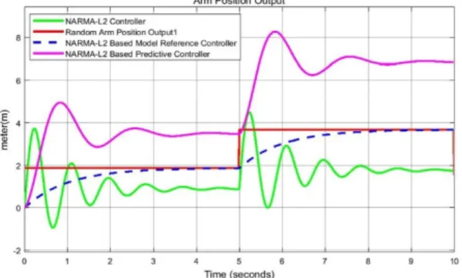
Fig. 15. Random input response simulation result
The neural network controller with NARMA-L2 controller random input signal is the desired arm position of the patient and the output of this controller has a peak value of 4.4 m while the desired arm position is 3.5m. This show us that the neural network controller with NARMA-L2 controller gives high impulse voltage to the nerve of the arm. The neural network controller with NARMA-L2 model system identification based predictive controller random input signal is the desired arm position of the patient and the output of this controller has a peak value of 8.5 m while the desired arm position is 3.5 m. This show us that the neural network controller with NARMA-L2 model system identification based predictive controller feed excess nerve impulse voltage to the nerve of the arm. The neural network controller with NARMA-L2 model based model reference adaptive control random input signal is the desired arm position of the patient and the output of this controller has a peak value of 3.5 m while the desired arm position is 3.5 m. This show us that the neural network controller with NARMA-L2 model based model reference adaptive control gives the exact nerve impulse voltage to the nerve of the arm.
D. Numerical Value Comparison of the proposed systems
The numerical value comparison of the proposed systems is shown in the Table 1 bellow.
TABLE I NUMERICAL VALUE COMPARISON OF THE PROPOSED SYSTEMS
No System Step Sine wave Random
1 Desired Arm Position 1 1 3.5
2 NARMA-L2 model 0.5 0.6 4.4
3 Model reference 1 0.8 3.5
4 Predictive controller 1.75 2.1 8.5
The result from Table 1 shows us that the neural network controller with NARMA-L2 model based model reference adaptive control show the best response.
IV. CONCLUSION
In this thesis, nerves system based arm position sensor device is used to measure the exact arm position for nerve patients using the proposed systems. Three different systems are proposed which are a neural network controller is designed with NARMA-L2 model, neural network controller is designed with NARMA-L2 model system identification based predictive controller and neural network controller is designed with NARMA-L2 model based model reference adaptive control system.
The proposed controllers are tested for comparing the actual and desired arm position of the nerves system based arm position sensor device for three desired arm position inputs (step, sine wave and random).
The simulation result for a step input signals shows that the neural network controller with NARMA-L2 controller feeds a high impulse voltage to the nerve of the arm and the neural network controller with NARMA-L2 model system identification based predictive controller feed excess nerve impulse voltage to the nerve of the arm and the neural network controller with NARMA-L2 model based model reference adaptive control gives the exact nerve impulse voltage to the nerve of the arm.
The simulation result for a sine wave input signals shows that the neural network controller with NARMA-L2 controller gives high nerve impulse voltage to the nerve of the arm and the neural network controller with NARMA-L2 model system identification based predictive controller feed excess nerve impulse voltage to the nerve of the arm and the neural network controller with NARMA-L2 model based model reference adaptive control gives the exact nerve impulse voltage to the nerve of the arm.
controller gives high nerve impulse voltage to the nerve of the arm and the neural network controller with NARMA-L2 model system identification based predictive controller feed excess nerve impulse voltage to the nerve of the arm and the neural network controller with NARMA-L2 model based model reference adaptive control gives the exact nerve impulse voltage to the nerve of the arm.
Finally, the comparative simulation result prove the effectiveness of the presented neural network controller with NARMAL2 model based model reference adaptive control and it achieves to balance between the actual and desired arm position tests for the nerve patient by adjusting the nerve impulse voltage given to the arm.
REFERENCES
[1]. T. A. Al-Zohary “Adaptive Control of Nonlinear Multivariable Systems Using Neural Networks and Approximate Models” Computer and Systems Eng. Dept. Fac. Of Eng. Ain Shams University, 2018. [2]. Yousif Al-Dunainawi “A New MIMO ANFIS-PSO Based NARMA-L2 Controller for Nonlinear Dynamic
Systems” IEEE Control Syst. Soc., vol. 1, p. 246, 2017.
[3]. Cidambaram Vijay Nagaraj “Design of Buck Boost Converter for Nonlinear Systems using Adaptive Controller” Engineering and Technology, Pudukkottai-622507, Tamil Nadu, India, 2017.
[4]. Mehdi Ramezani “Design of NARMA L-2 Control of Nonlinear Inverted Pendulum” International Research Journal of Applied and Basic Sciences, 2016
[5]. NgocKhoat Nguyen “An Investigation of Intelligent Controllers Based on Fuzzy Logic and Artificial Neural Network for Power System Frequency Maintenance” Turkish Journal of Electrical Engineering & Computer Sciences, (2016) 24: 2893 – 2909.
[6]. Dhanraj Suman “Implementation of Narma-L2 Controller for Magnetic Levitation System” 6th international
conference on science technology and management, 04 Dec, 2016.
[7]. Pratik Ghutke “Performance Analysis of Neural Network Based Narma Control for CSTR” International Journal for Innovative Research in Science & Technology| Volume 1 | Issue 8 | January 2015.
[8]. Cabrera, J. B. D. and Narendra, K. S., "On Regulation and Tracking in Nonlinear Discrete” Univ., New Haven, CT, Tech. Rep, 2015.
[9]. Cabrera, J. B. D. and Narendra, K. S., "On Regulation and Tracking in Nonlinear Discrete” Univ., New Haven, CT, Tech. Rep, 2015.
[10].Priyanka Sharma “NARMA-L2 Controller for Five-Area Load Frequency Control” Int. Jour. of App. Sc. and Eng. (IJASE) 2(2): Dec 2014, 91-101.
[11].Razika Zamoum Boushaki “Artificial Neural Network Control of the Recycle Compression System” Studies in Informatics and Control, Vol. 23, No. 1, March 2014.
[12].Priyanka Sharma “NARMA-L2 Controller for Five-Area Load Frequency Control” Proceedings of the IEEE 2014; 121(7):601–8.