2017 2nd International Conference on Artificial Intelligence and Engineering Applications (AIEA 2017)
ISBN: 978-1-60595-485-1
Design and Implementation of Cross-hole CT Data
Acquisition System
FAQUAN ZHANG, RUIHUAN HUANG, GUOFU WANG, JINCAI YE and SI HU
ABSTRACT
Aiming at the problems of small dynamic range, low signal-to-noise ratio and inaccurate data acquisition of the existing cross-hole CT exploration instrument, the cross-hole CT data acquisition system is designed basing on DSP processor and low-noise high-precision A/D converter. According to signal amplitude range, it can be chosen to do signal amplification and attenuation or straight through processing, control signal to the proper sampling A/D converter, then the FIR low-pass filter is used to filter the signals, and the processed data is transmitted to the PC through the Ethernet port. The test results show that the system has large signal range, high signal-to-noise ratio, and high accuracy of data acquisition, the inversion profile coincides with the borehole verification.
KEYWORDS
Cross-hole CT, The data collection, High dynamic range, High signal to noise ratio.
INTRODUCTION
The cross-hole CT exploration instrument takes the way of running the pole to supply electricity and gather data, but it leads to a relatively large dynamic range of the collected signal[1-2]. There are two more extreme cases, one is that when measuring electrodes are close to the supply electrode, the potential difference of the electrode may be great, it would affect the accuracy of data. At worst, it will burn A/D converter. Another is that the measuring electrode from the power supply electrode is far away, the signal is very weak, only microvolt level. It does not come up to the effective conversion range of the A/D converter. At present, the traditional cross-hole CT prospecting apparatus don't handle the mechanism of high dynamic range signal very well, the resolution of the instrument is low, and the accuracy of the measured data is not high in two extreme cases [3-5].
Taking a low-power high-speed DSP C6657 processor as the core, we design a data acquisition system with high dynamic range and high signal-to-noise ratio. It improves the accuracy of data acquisition, the inversion profile agrees well with the borehole.
_________________________________________
SYSTEM DESIGN
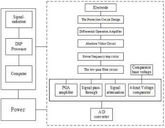
Fig. 1 is a system block diagram of a cross-hole CT explorer that is a complete system, which focuses on the data acquisition section of the cross-hole CT Explorer.
The data acquisition part is shown in Fig. 1. The cross-hole CT data acquisition system is mainly composed of protection circuit, differential amplifier circuit, low-pass filter circuit, and DSP.
SYSTEM HARDWARE DESIGN
The Protection Circuit Design
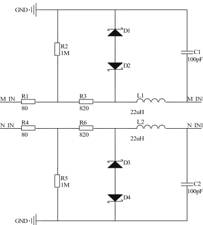
[image:2.612.127.468.340.604.2]Because the transmission current of the cross-hole CT probe is relatively large. In order to prevent the operation led to the failure of the input signal input suddenly greatly damaged equipment in, the design of protection circuit on the input side plays the role of protection. Several diodes in Fig. 2 play the role of overvoltage protection, and passive LC filters can suppress differential mode interference. The two input signals M_IN and N_IN in Fig. 2 are the signals of the common electrode and the signals of the measuring electrodes.
D1
22uH L1 R1
80
100pF C1 R2
1M
R3
820
D2 GND
M_IN
D3 22uH
L2 R4
80
100pF C2 R5
1M R6
820
D4
GND N_IN
M_IN1
N_IN1
Figure 2. the protection circuit design.
Differential Operation Amplifier
Because the input impedance of the amplifier will affect the grounding resistance of the electrode, and the input impedance will be affected by the device noise. So selecting an amplifier OPA301 with low noise, high input impedance and taking the way of the differential input can effectively suppress common mode interference. As shown in Fig. 3, according to the principle of the fault, the current flowing through R7 and R8 is equal and the current flowing through R9 and R10 is equal. Calculation formula:
V OUT=(N IN1 M IN1) / R 9 V / R 10 (1)
7 8
(M IN1 V ) / R (V OUT V ) / R (2)
By the virtual short known V-=V+, by R7=R8, R9=R10, can be seen:
V O U T = ( N IN 1 M IN 1) (3)
[image:3.612.195.396.56.279.2]The essence of this circuit is a subtractor, The difference between the two voltage signals makes it possible to suppress common mode interference.
The low-pass filter circuit
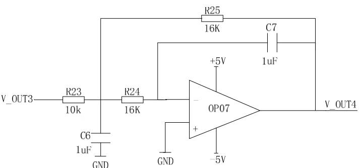
Because the signal frequency of the transmitted signal transmitting module is 1.25Hz, which belong to the low frequency signal. In order to filter out-of-band high-frequency signal, the design of a cut-off high-frequency of 100Hz second-order Butterworth low-pass filter for low-pass filter. As shown in Fig. 4, R23 and C6 form a low pass in graph, R24 and C7 constitute the integral level, the two levels also has low pass characteristics.
7 6 25 24 0
2 1
C C R R f
(4)
6
23 24 25
24 25 7 C Q R / /R / /R
R R C
( )
(5)
In the formula (4), the cutoff frequency of the low-pass filter is 100Hz, which is different from the center frequency of the notch filter. From = 100Hz and C6 = C7 = 1uF, R24 = R25 = 16K, according to the equivalent quality factor Q = 0.71 of the low pass filter, R23 = 10K.
SYSTEM SOFTWARE DESIGN
Digital filter design
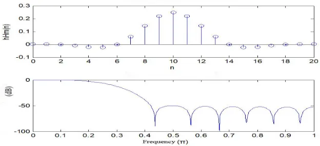
[image:4.612.120.476.528.695.2]In order to improve the accuracy of the data acquisition system, it is necessary to filter out the noise of the system. According to the characteristics of the system launch signal, the design cuts off frequency of 3Hz, sampling frequency of 30Hz, the order of 21 low-pass filter, with Hamming window for interception. Hamming window with energy mainly concentrated in the main lobe, accounting for 99.6%, the first side of the peak of the peak is smaller than the main lap 40dB advantages. Hamming window’s window function is.
Figure 5. Spectrum of low-pass filtering. ) ( )] 1 2 cos( 46 . 0 54 . 0 [ ) (
H R n
N n
n N
m
(6)
When N is the order of the filter, and RN(n)
is the rectangular window sequence. ( ) 1, 0 1
0, ot hers
N n N
R n (7)
The method of designing a linear phase FIR low-pass filter with Hamming window is as follows. First, the unit impulse response corresponding to the frequency response is determined,
( ) s in [ ( )], 1
( ) 2
c d n N h n n
(8) The actual impulse response and spectrum of the Hamming window filter are shown in Fig. 5.
The data inversion
The processed data need to upload to PC for storage. Using the data inversion software, the resistivity distribution section of two boreholes can be inverted, and the actual geological information can be obtained by combining the geological data of the existing geological exploration areas.
THE RESULTS OF FIELD TEST
Figure 6. Inversion profile of cross-hole CT.
As can be seen from the Fig. 6. The bedrock surface depth is shallow, in the range of 0 to -14 m. The whole section is dissociated and divided into two types. One is honeycomb-shaped dissolution area, the depth is roughly -28m to -50m. It is primarily the mass joints of caves, the fissure development of caves and the development of small caves. The other is the cave development area, the cave goes through, and the depth is roughly -14m to -58m. The Late borehole verification is in good agreement with profile analysis.
CONCLUSION
This system can capture high dynamic range signal without distortion, no clipping phenomenon. It can guarantee the accuracy of the collected data. Because the effective data is the guarantee of inversion. This system ensures the accuracy of the collected data, what's more, inversion of the profile coincides with the actual drilling test.
REFERENCES
1. Hua Wang, Hongguang Ji. Study on CT prospecting technology by the pole-pole cross-hole direct-current resistivity method [J]. Progress in Geophysics.2010, 25(5): 1833-1840.
2. Jiayong Yan, Guixiang Meng,Qingtian Lv, et al. Progress and Prospect of High-density Electrical. Geophysical and Geochemical Exploration. 2012.36(4): 576-584.
3. Xiaobin Hu, Xinhui Zhang. Design of Multi-channel and Precision Digital Collecting and Storage System. Automation & Instrumentation. 2012(1): 48-52.
4. Gang He, Jun Wang, Biyong Zhang,et al. Design of High-density Electrical Method Data Acquisition System. Instrument Technique and Sensor. 2014 (8).
5. Biyong Zhang, Gang He, Jun Wang. New High-Electrical Instrument Measuring System. Instrument Technique and Sensor. 2014(1): 24-26.
6. Qingcheng Qiu, Weihe Li. Application of the Cross-hole CT Tomography in Karst [J]. Geophysical and Geochemical Exploration. 2001, 25(3): 236-240.