2018 International Conference on Modeling, Simulation and Analysis (ICMSA 2018) ISBN: 978-1-60595-544-5
Effect of Structural Parameters on the Stiffness of Truss Structure
Qi ZHANG
1and Jia-jun HONG
2,*1
School of Aeronautic Science and Engineering, Beihang University, Beijing 100191, PR China
2
School of Mechanical Engineering, Shanghai Jiao Tong University, Shanghai 200240, PR China
*Corresponding author
Keywords: Truss, Stiffness, Finite element model, Beam.
Abstract. Stiffness is an important parameter during the designment of truss structure. A finite element model (FEM) was put forward to calculate the stiffness of truss structure. The proposed FEM was compared with the universal theoretical model to verify the rationality of FEM. The verified FEM was further used to research the effect of structural parameters on the stiffness of truss structure. The variations of stiffness with length of truss, size of cross section, and spacing of cell were illustrated. The calculated results showed a nonlinear relationship between stiffness and structural parameter. At last, the underlying mechanism of the nonlinear relationship was discussed.
Introduction
Truss structure is widely used in bridge, aerospace and construction because its high ratio of stiffness to mass. The mechanical property of truss structure has been one of the long-standing issues in structural mechanics. Truss structure needs enough stiffness to support external loading; otherwise, security incidents easily happen if truss is put into use. In order to make sure the safety of truss structure, the stiffness of truss structure should be calculated before truss structure is used in engineering.
For uniform beam structure, there is a classical theory to calculate the stiffness of beam [1]. The theoretical model is useful for the homogeneous beam section. For truss structure, the sections of truss are inhomogeneous; therefore, the available theory is useless to calculate the stiffness of truss. Fortunately, it has been demonstrated that finite element model (FEM) is a valid technology to analyze mechanical properties of truss structure [2-5]. From then on, the FEMs of truss structure have been widely researched. In order to analyze the elasto-plastic small-deformation, an extended multiscale finite element method was developed for 2D periodic lattice truss materials [6]. Before using FEM to predict the deformation of truss structure, the differences between matrix displacement method and finite element method were analyzed [7]. Based on the stiffness and load matrix of bridge frames, a FEM was established to calculate the lateral displacement under the loading of wind [8]. The initial yield surface of periodic 2D trusses of beams and evolution of the yield surface with ongoing hardening were both added into an asymptotic discrete expansion FEM to simulate the elastoplastic homogenized response of lattice truss structure [9]. In order to realize the geometrical nonlinear analysis of the structures with lattice truss materials, an equivalent continuum multiscale formulation was presented by combining the extended multiscale finite element method with the co-rotational approach [10]. Up to now, the effect of structural parameters on the stiffness of truss structure has not been explored.
Finite Element Model
The finite element model (FEM) aimed to simulate the mechanical behavior of truss structure, has been developed by means of Abaqus 6.11 [11, 12]. In order to research in detail the mechanical properties of truss structure, a 3D FEM has been defined accounting for the truss geometry, materials and boundary conditions.
The first modeling step is the characterization of the beam geometry accounting for the bending behavior of truss. A deformable 3D truss model was generated by means of planar commands. Concerning the meshing of the beam, the truss has been discretized by means of shear-flexible elements adopting the global seeds meshing technique. In order to favor convergence and reduce the computational time, the simplest element type has been chosen, the B31, that is a 2-node linear beam in space. The boundaries for simply supported beam was used here. The displacements for one side of the truss were constrained in both x direction and y direction. The displacement for the other side of the truss was constrained only in y direction. The concentrated force was exerted on the middle position of truss. A general and static procedure type was chosen to calculate the mechanical response of truss. When the calculations of the mechanical response of truss have been accomplished, the Mises stress and displacement are obtained by means of output databases. Based on the calculated Mises stress and displacement, the stiffness of truss was analyzed.
Verification of Finite Element Model
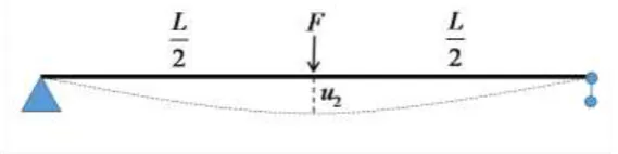
According to the description of FEM in Section 2, we can set up FEM of simply supported beam in Fig. 1. Two kinds of FEM were established: the length of beam is fixed and the loading force varies in the first FEM; the loading force is fixed and the length of beam varies in the other FEM. The material of the beam is steel. The shape of the section is thin-walled pipe with a diameter of 48 mm and a thickness of 3.5 mm. After FEM of beam is finished, the maximum of displacement u2 at midpoint is calculated.
In order to verify the rationality of FEM, the FEM results are compared with the universal
[image:2.595.157.442.537.608.2]theoretical model [1] where . Fig. 2 shows the comparison of FEM results and theoretical model. As illustrated in Fig. 2, FEM results are in accordance with the universal theoretical model no matter length of beam or loading force varies. The maximum of relative error is less than 0.7%. Therefore, the proposed FEM is valid to analyze the mechanical response of truss structure.
Figure 2. Comparison of theoretical model and FEM results: (a) variation of maximum of displacement with loading force for a given length of beam. (b) variation of maximum of displacement with length of beam for a loading force.
3D Abaqus Finite Element Model of Truss
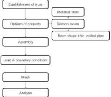
Building 3D ABAQUS finite element model of truss needs a few steps (see Fig. 3). The first step is to establish the model of truss in ABAQUS, where the length of truss is L, the size of cross section is D×D, and the spacing of cell is Lc. The next step is to set the properties of truss as steel beam with the shape of thin-walled pipe. After mashing step, the number of elements and nodes are around 1400 and 1320 respectively. The loading forces are set at midpoint of the truss structure. The left side of truss is hinged support and the right side is only fixed at the vertical direction; therefore, the truss is a simply supported beam in FEM. The final FEM of truss structure is illustrated in Fig. 4. The maximum of displacement can be detected in the results of fully analysis.
[image:3.595.205.395.548.713.2]Figure 4. FEM of truss where the primary parameters are labeled.
According to the universal theoretical model [1], for the loading force at the midpoint of a simply
supported beam, the maximum displacement is , where is the maximum displacement of the beam, is loading force and L is the length of truss. Based on the calculated displacement at the loading force F, we can get the stiffness of truss by:
. (1)
Effect of Structural Parameters on Truss Stiffness
Using 3D ABAQUS finite element model of truss structure, the effect of length of truss on truss stiffness was researched. Fig. 5 shows the calculated results of truss stiffness. The stiffness of truss structure increases with the increasing length of truss. When the length of truss is less than 15 m, the stiffness of truss increases rapidly with the increasing length of truss; however, the stiffness of truss increases slowly with the increasing length of truss if the length of truss is beyond 15 m. In the universal theoretical model [1], the stiffness of beam is related with the modulus and moment of inertia, and therefore the length of beam can not affact the stiffness of beam. For truss structure, the length of truss affacts the stiffness of truss (see Fig. 6). According to polynomial fitting, the variation of stiffness with truss length is given by:
, (2) Where E1 is the stiffness of truss and L is the length of truss. The relationship between stiffness and
truss length is a cubic polynomial equation.
Figure 5. Variation of stiffness with length of truss.
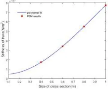
[image:4.595.192.405.543.700.2]section exceeds 0.4 m. When the the size of cross section is beyond 0.5 m, the relationship between the stiffness of truss and the size of cross section is nearly linear. For truss structure, the size of cross section affacts the stiffness of truss (see Fig. 6). According to polynomial fitting, the variation of stiffness with the size of cross section is given by:
[image:5.595.206.386.189.339.2], (3) where is the stiffness of truss and is the size of cross section. The relationship between stiffness and cross section is a cubic polynomial equation.
Figure 6. Variation of stiffness with size of cross section.
The effect of cell spacing on truss stiffness was further studied by using 3D ABAQUS finite element model of truss structure. The calculated results of truss stiffness were illustrated in Fig. 7. The stiffness of truss structure firstly increases with the increasing cell spacing, and then decreases with the increasing cell spacing. There is a maximum of stiffness when spacing of cell varies in a certain range. According to polynomial fitting, the variation of stiffness with cell spacing is in the following form:
, (4) where E3 is the stiffness of truss and Lc is the spacing of cell. The relationship between stiffness and
spacing cell is a quartic polynomial equation. Based on the fitting curve in Fig. 8, the stiffness of truss has a maximum if the spacing of cell is about 0.7 m. The cell spacing of 0.7 m is the optimal designment, which leads to the maximum of truss stiffness.
Figure 7. Variation of stiffness with spacing of cell.
Concluding Remarks
[image:5.595.197.401.534.686.2]model. The comparisons of FEM and theoretical model verified the rationality of the proposed FEM. FEM was further used to research the effect of structural parameters on the stiffness of truss structure. Unlike the universal theoretical model, the stiffness of truss varies with the structural parameters. The stiffness of truss structure increases with the increasing length of truss. The stiffness of truss structure increases with the increasing size of cross section. The stiffness of truss structure firstly increases with the increasing cell spacing, and then decreases with the increasing cell spacing. There is an optical cell spacing during the designment of truss structure. Finally, the proposed FEM can be used to design truss structures and help to improve the mechanical properties of truss structures.
Acknowledgement
This research was financially supported by Fundamental Research Funds for Universities (Grant No. FRFU-18-210A).
References
[1] F. P. Beer, E. R. Johnston, J. T. DeWolf. Mechanics of Materials, Fourth Edition. The McGraw-Hill Companies, Inc. New York, 2006.
[2] J.M. Guedes, N. Kikuchi. Preprocessing and postprocessing for materials based on the homogenization method with adaptive finite elementmethods. Comput. Methods Appl. Mech. Eng. 83 (1990) 143-198.
[3] J. Yan, G.D. Cheng, S.T. Liu, et al. Comparison of prediction on effective elastic property and shape optimization of truss material with periodic microstructure. Int. J. Mech. Sci. 48 (2006) 400-413.
[4] K. Terada, N. Kikuchi. A class of general algorithms for multiscale analyses of heterogeneous media. Comput. Methods Appl. Mech. Eng. 190 (2001) 5427-5464.
[5] C. Miehe, C.G. Bayreuther. On multiscale FE analyses of heterogeneous structures: From homogenization tomultigrid solvers. Int. J. Numer. Methods Eng. 71 (2007) 1135-1180.
[6] T.Y. Hou, X.H. Wu, Z.Q. Cai. Convergence of a multiscale finite element method for elliptic problems with rapidly oscillating coefficients. Math. Comput. 68 (1999) 913-943.
[7] J.E. Aarnes, S. Krogstad, K.A. Lie. A hierarchical multiscale method for two-phase flow based upon mixed finite elements and nonuniform coarse grids. Multiscale Model. Simul. 2 (2006) 337-363.
[8] J.C. Wu, X.Q. Shi, S.J. Ye, et al. Numerical simulation of land subsidence induced by groundwater overexploitation in Su-Xi-Chang area, China. Environ. Geol. 57 (2009) 1409-1421.
[9] Y. Efendiev, T. Hou, V. Ginting. Multiscale finite element methods for nonlinear problems and their applications. Commun. Math. Sci. 2 (2004) 553-589.
[10] G.M. Verderame, G. De Carlo, P. Ricci, G. Fabbrocino. Cyclic bond behavior of plain bars. Part II: analytical investigation. J Constr Build Mater. 23 (2009) 3512-3522.
[11] G. Desiderio, M. Latour, G. Rizzano. Modellazione Analitica e FEM del Meccanismo di trasferimento degli sforzi tra Fondello in Acciaio e Calcestruzzo nelle Travi PREM. Proceeding of XIV Convegno ANIDIS "L'Ingegneria Sismica in Italia", Bari, CD-rom; 2011.