e _ e e e e e.e
e
e e e e e
0
e Gee 000 0 0 e Gee e e _ 000
1Reference Drawing
Collating List of Pages
This reference drawing contains the collating sequence, page side, and EC level of pages for IBM 3480 Magnetic Tape Subsystem Maintenance Information Manual (MI) Volume A03, SY32-5050-12.
The part number of the divider tab list is 8673745. This reference drawing is to be placed at the front of the manual.
PAGE SIDE LEVEL PAGE SIDE LEVEL PAGE SIDE LEVEL PAGE SIDE LEVEL
CARR-DR 190 Back EC 336396 CARR-DR 380 Front EC 336395
FRONT COVER Front ECA57724 CARR-DR 5 Front EC 336396 CARR-DR 388 Back EC 336395
PREF 1 Back EC 336395 CARR-DR 8 Back EC 336396 CARR-DR 200 Front EC 336396
CARR-DR 205 Back EC 336395 CARR-DR 390 Front EC 336395
TAB 1 Front EC 336395 CARR-DR 9 Front EC 336396 CARR-DR 400 Back EC 336395
TAB 2 Back EC 336395 CARR-DR 10 Back EC 336396 CARR-DR 210 Front EC A57723
CARR-DR 300 Back EC 336396 CARR-DR 410 Front EC 336395
CARR-DR Tab CARR-DR 11 Front EC 336396 CARR-DR 420 Back EC 336395
CARR-DR 20 Back ECA57721 CARR-DR 305 Front EC 336396
.~
CARR-DR 1-1 Front EC A57723 CARR-DR 310 Back EC 336396 CARR-DR 430 Front EC 336395
CARR-DR 1-2 Back ECA57721 CARR-DR 30 Front EC 336396 CARR-DR 440 Back EC 336395
CARR-DR 40 Back EC 336396 CARR-DR 315 Front EC 336396
CARR-DR 1-3 Front EC A57721 CARR-DR 318 Back EC 336396 CARR-DR 450 Front EC 336395
CARR-DR 1-4 Back ECA57721 CARR-DR 41 Front EC 336396 CARR-DR 460 Back EC 336395
CARR-DR 50 Back EC 336396 CARR-DR 320 Front EC 336396
CARR-DR 1-5 Front EC A57724 CARR-DR 325 Back EC 336396 CARR-DR 470 Front EC 336396
CARR-DR 1-7 Back EC A57723 CARR-DR 60 Front EC 336396 CARR-DR 490 Back EC 336396
CARR-DR 70 Back EC 336396 CARR-DR 328 Front EC 336396
CARR-DR 1-8 Front EC 336396 CARR-DR 330 Back EC 336396 CARR-DR 491 Front EC 336396
CARR-DR 1-9 Back EC A57723 ..cARR-DR 80 Front EC 336396 CARR-DR 540 Back EC 336396
CARR-DR 90 Back ECA47957 CARR-DR 335 Front EC 336395
CARR-DR 2-1 Front EC 336395 CARR-DR 340 Back EC 336395 CARR-DR 545 Front EC 336396
CARR-DR 2-2 Back EC 336395 CARR-DR 91 Front EC 336396 CARR-DR 580 Back EC 336396
CARR-DR 100 Back EC 336396 CARR-DR 345 Front EC 336395
CARR-DR 2-3 Front EC 336396 CARR-DR 348 Back EC 336395 CARR-DR 581 Front EC 336396
CARR-DR 2-4 Back EC 336396 CARR-DR 110 Front EC 336396 CARR-DR 590 Back EC 336396
CARR-DR 120 Back EC 336396 CARR-DR 350 Front EC 336395
CARR-DR 2-5 Front EC 336396 CARR-DR 355 Back EC 336395 CARR-DR 600 Front EC 336395
CARR-DR 2-6 Back EC 336396 CARR-DR 130 Front EC A57723 CARR-DR 610 Back EC 336395
CARR-DR 131 Back EC A57723 CARR-DR 358 Front EC 336396
CARR-DR 2-8 Front EC 336396 CARR-DR 360 Back EC 336396 CARR-DR 640 Front EC 336395
CARR-DR 2-9 Back ECA57721 CARR-DR 132 Front EC A57723 CARR-DR 650 Back EC 336395
CARR-DR 140 Back EC 336396 CARR-DR 365 Front EC 336396
CARR-DR 3-1 Front EC 336396 CARR-DR 368 Back EC 336396 CARR-DR 655 Front EC 336396
CARR-DR 3-2 Back EC A57723 CARR-DR 160 Front EC 336396 CARR-DR 658 Back EC 336396
CARR-DR 170 Back EC 336396 CARR-DR 370 Front EC 336395
CARR-DR 3-3 Front EC 336395 CARR-DR 378 Back EC 336395 CARR-DR 660 Front EC 336396
CARR-DR 4 Back EC 336395 CARR-DR 180 Front EC 336396 CARR-DR 710 Back EC 336396
PAGE SIDE
CARR-DR 718 Front CARR-DR 750 Back CARR-DR 765 Front CARR-DR 790 Back CARR-DR 791 Front CARR-DR 794 Back CARR-DR 795 Front CARR-DR 796 Back CARR-DR 800 Front CARR-DR 805 Back CARR-DR 810 Front CARR-DR 815 Back CARR-DR 820 Front CARR-DR 823 Back CARR-DR 825 Front CARR-DR 830 Back CARR-DR 833 Front CARR-DR 835 Back CARR-DR 850 Front CARR-DR 880 Back CARR-DR 900 Front CARR-DR 905 Back CARR-DR 950 Front CARR-DR 955 Back CARR-DR 960 Front CARR-DR 1040 Back CARR-DR 1045 Front CARR-DR 1090 Back CARR-DR 1100 Front CARR-DR 1105 Back CARR-DR 1110 Front CARR-DR 1270 Back CARR-DR 1290 Front CARR-DR 1295 Back
3480 MI LEVEL EC A47957 EC A47957 EC 336395 EC 336395 EC 336396 EC 336396 EC 336396 EC 336396 EC 336396 EC 336396 EC 336396 EC 336396 EC 336395 EC 336395 EC 336395 EC 336395 EC 336395 EC 336395 EC 336396 EC 336396 EC 336396 EC 336396 EC 336395 EC 336395 EC A47957 EC 336396 EC 336395 EC 336395 EC A57723 EC 336396 EC 336396 EC 336396 EC 336396 EC 336396
.,
PAGE SIDE LEVEL
CARR-DR 1610 Front EC 336396 CARR-DR 2110 Back EC A57721 CARR-DR 2113 Front EC 336396 CARR-DR 2115 Back EC 336396 CARR-DR 2116 Front EC 336396 CARR-DR 2120 Back EC 336396 CARR-DR 2130 Front EC 336396 CARR-DR 2150 Back EC 336396 CARR-DR 2160 Front EC 336396 CARR-DR 2180 Back EC 336396 CARR-DR 2185 Front EC 336396 CARR-DR 2190 Back EC 336396 CARR-DR 2230 Front EC 336395 CARR-DR 2250 Back EC 336395 CARR-DR 2260 Front EC 336395 CARR-DR 2270 Back EC 336395 CARR-DR 2280 Front EC 336395 CARR-DR 2290 Back EC 336395 CARR-DR 2300 Front EC 336396 CARR-DR 2310 Back EC 336396 CARR-DR 2320 Front EC 336395 CARR-DR 2620 Back EC 336395 CARR-DR 2630 Front EC 336395 CARR-DR 2690 Back EC 336395 CARR-DR 2770 Front EC 336396 CARR-DR 2775 Back EC 336396 CARR-DR 2810 Front EC 336396 CARR-DR 2820 Back EC 336396 CARR-DR 2830 Front EC 336396 CARR-DR 2835 Back EC 336396 CARR-DR 2840 Front EC 336396 CARR-DR 2850 Back EC A47957 CARR-DR 2851 Front EC 336396 CARR-DR 2860 Back EC A57721
,
•
J
Reference Drawing
PAGE SIDE LEVEL
CARR-DR 2880 Front EC 336395 CARR-DR 2890 Back EC A57723 CARR-DR 2900 Front EC 336396 CARR-DR 2910 Back EC 336396 CARR-DR 2920 Front EC A57721 CARR-DR 2930 Back EC 336396 CARR-DR 2940 Front EC 336395 CARR-DR 2950 Back EC 336395 CARR-DR 2960 Front EC A57723 CARR-DR 2970 Back EC A57723 CARR-DR 2980 Front EC 336396 CARR-DR 3000 Back EC A57723 RCF-1 Front
RCF-2 Back
A03-2
,
~ , ~,
..
I
J,
J
,
J
W:m
8673863
C")
~
C")~ ,
i
,PUBLICATIONS REFERENCE DRAWING
..
MACHINE TYPE/MODEL NO. 3480
MACHINE NAME - Magnetic Tape Subsystem
..
'..
FORM NO •
E C NO.
DESCRIPTION
1 COMMENTS
.
SY32-5050-0
991552
VOL. A03 - Maintenance Information
••• 1336326
TNL SN32-0309
IEC 0011225741 (REA 12-25743)
..
IEC 0021225741 (REA 12-25493)
SY32-5050-1
336389
Second Edition
..
IEC 0011225996
SY32-5050-2
336390
Third Edition
IEC 0011225997
IEC 0011215157
SY32-5050-3
336391
Fourth Edition
REA 77-11223
IEC 0011215158
REA 12-11922
REA 12-15151
IEC 0011215159
IEC 0011225842
IEC 0011225843
SY32-5050-4
336392
Fifth Edition
-
IEC 0011225998
IEC 0011228481
336393
TNL SN32-5036
SY32-5050-5
336394
Sixth Edition
SY32·5050-6
336395
Seventh Edition
IEC 0011225844
SY32-5050-7
336396
Eighth Edition
IEC 0011222985
SY32-5050-8
A47957C
Ninth Edition
SY32-5050-9
A57693·
Tenth Edition
SY32-5050-10
A57721
Eleventh Edition
SY32-5050-11
A57723
Twelfth Edition
SY32-5050-12
. A57724,
Thirteenth Edition
,
1
I
IB111
DATE
CHANGE NO
DATE
CHANGE NO
NAME.
PUB 'REF OWG (PRO)
REL
See EC History
.
I •7/24/89
. ,.A57723
,~
I
DEstGN
SHT
OF
.5/11/90
I;·A57724·
-...J
W
DETAIL
ico
0)
CHECK
CLASSIFICATION MUST CONFORM TO ENG SPECDeVELOPMENT NO
LOGIC PG NO
W
'.
,
i
)
,
,
" I
,
I
,
J
J
t
.J
I)
e e e e e
G
e -
e
0 0 0 "
e
C G
eGO c e o 0 0 0 0 GOO 0 0 0 0 0
3480 Magnetic Tape Subsystem
- - . . .
-
---
-
-
- - - -
-
---
~---
-
-
----
-~-.--.,-
Maintenance Information
3480
3480
S/N-
S/N-MI
MI
Maintenance
Maintenance
Information
Information
: GLOSS
PWR
PLAN
SENSE
INTRO
PANEL
*START*
MD
CART
LOC
PNEU
CARR-CU
MSG
INST
INSP
INDEX
--- .-
---Vol AOI
Vol A02
Maintenance Library
Maintenance Infonnation
Logic Diagrams
3480
3480
3480
S/N-
S/N-
S/N-MI
MI
MI
Maintenance
Maintenance
Maintenance
Information
Information
Information
CARR-DR
LGND
FSI
SPROC
EAD
SDISK
DIAG
OF
OPER
I
Vol A03
I
Vol A04
Vol AOS
. .
-- Vols. A01 to AOS
Vols. C01 and 001
. . - _ .. --_ .. - .
-SY32 - 5050 - 12
Preface
This manual contains maintenance information about the IBM 3480 Magnetic Tape Subsystem and is intended for customer engineers responsible for servicing the 3480 tape subsystem. This publication is designed to be used with the IBM
Maintenance Device (MD). Therefore, CEs using this manual should be familiar with that tool.
Prerequisite Knowledge
It is assumed that you have a background in data processing concepts and that you are familiar with the hexadecimal numbering system, stored program concepts, and have a basic understanding of tape subsystems and their relationship to a processor I/O channel.
3480 MI
EC336395
© Copyright IBM Corp. 19B4. 1985. 1986
Related Publications
IBM System/360 and System/370 I/O Interface Channel to Control Unit Original Equipment Manufacturers' Information,
GA22-6974.
IBM 3480 Magnetic Tape Subsystem Description, GA32-0042.
How to Update the Maintenance
Information
This manual is form number controlled. The 3480 manuals will be updated by Technical Newsletters (TNLs). The TNL cover letter will indicate the new EC level. The entire manual will be updated by major revision. All updates are processed through normal MLC control. The Publications Reference Drawing (PRO) in the front of each volume contains the EC history.
"
; I
,
If
How to Order This Manual
This manual or pages can be ordered from one of the following: • United States
• Europe/Middle East/Asia (E/ME/A) • Americas/Far East (A/FE)
Use the wiring Diagram/Logic Page Request form, Z 150-0 130. Be sure to include the form number of the manual when ordering the new manual or pages. Please write your telephone number on the form in case there are any questions regarding your order.
United States
IBM Corporation
General Products Division Dept.30L
Tucson, Arizona 85744
E/ME/A
International Business Machines S.A.E., Division de Fabricacion Dept. 9290
Valencia, Spain
A/FE
't
I
IBM Argentina SA Dept. 020 H. Yrigoyen 2149 1640
Martinec, Pcia. Buenos Aires Republic of Argentina
~
j
l
.~
,
I
j }I
Preface
PREF 1
Preface
PREF 1
•
o
o
o
o
o
o
o
o
o
o
Tab List
Tab List
TAB 1
Volume A01
Volume A02
Volume A03
Volume A04
GLOSS Glossary PWR Power Maps CARR-DR Drive Checks/ Adjustments/Removal/Replacement LGND Legend
PLAN Maintenance Plan SENSE Sense/Status SPROC
Support Procedures
INTRO 3480 Introduction PANEL Panel
SDISK Support Diskette Procedures
START Start Maintenance MD Maintenance Device DIAG
Support Diagnostic Descriptions
CART Cartridge Analysis LOC . Locations
DF Data Fields and Registers PNEU Pneumatic Analysis
MSG Console Messages and EREP
CARR-CU Control Unit
Checks/ Adjustments/Removal/Replacement OPER Theory of Operation
INST Installation/Removal INSP Safety Check Procedures
INDEX Index
Volume A05
FSI Fault Symptom Index EAD Error Analysis Diagrams
3480 MI
EC336395
Notes
3480 MI
EC336395
C> Copyright IBM Corp. 1984. 19B5. 1986 \
J
Notes
TAB 2
Notes
TAB 2
RemoAePlace proce&s
by FRU
NunDr
o
o
This directory lists all field-replaceable units (FRUs) for the 3480 Tape Subsystem, and includes all control unit and drive assembly FRUs. To locate a specific FRU removal or replacement procedure, use the FRU number displayed on the maintenance device (MD) and perform the following:
1. Locate the FRU number in the FRU NUMBER column.
2. The VOLUME column indicates where the information for the FRU is located. Volume A02 contains the information for the control unit Volume A03 contains
the
information for the drive. The name of the FRU is listed in the FRU NAME column.3. Go to the page listed in the REMOVE column to perform the removal procedure. 4. Go to the page listed in the REPLACE column to perform the replacement procedure. Control Unit cover removals and replacements are described on CARR-CU 2-1 through 2-4. Drive cover removals and replacements are described on CARR-DR 2-1 through 2-6. Plenum supply hose clamping procedures are described on CARR-DR 3-1.
Tape lifter solenoid response time checking procedures are described on CARR-DR 3-2. Device interconnections checks are described on CARR-DR 3-3.
CU WITH BMM . . DRIVE WITH BM 84800011 FRUNUMBER VOLUME FRU NAME REMOVE REPLACE
PAGE PAGE
FRUool A03 Threader Assembly 10 10
FRU002 A03 Latch Solenoid 20 20
FRU003 A03 File Reel Motor 30 30
FRUOO4 A03 Machine Reel Mo1or and Hub Mount 40 40
FRUOOS A03 Lower Flange 50 50
FRU008 A03 Tape Path Sensor A 80 80
FRU007 A03 Tape Path Sensor B 70 70
FRUOOS A03 cartridge Latch Assembly 80 80
FRUOO9 A03 File Protect SwHch 90 90
FRU010 A03 cartridge Present Sen sor 100 100 FRUOll A03 Cartridge Latched Sensor 110 110
FRU012 A03 Decoupler Assembly 120 120
FRU013 A03 Head and Guide Assembly 130 130
FRU014 A03 Tension Transducer 140 140
FRUOIS A02 A1V5-A2V3 Cable 150 150
FRUOIS A03 Latch Spring 160 160
FRU017 A03 Plunger Spring 170 170
FRUOIS A03 Compression Spring 180 180
FRU019 A03 Interlock Spring 190 190
FRU020 A03 Blo_r Assembly 200 200
FRU022 A02 Read Bus Cable· Local 150 150 FRU024· A02 Read Bus Cable - Remote 150 150 FRU02S" A02 Read Bus Cable· Remote 150 150 FRU026 " A02 Device Data Bus cable· Remo1e 150 150 FRU027 A02 Device Data Bus cable· Remo1e 150 150 FRU029 A02 DevIce Data Bus cable· Local 150 150
FRU030 A03 Pump Motor 300 300
FRU031 A03 Regulator (60 Hz) 310 310
A03 Regulator (50 Hz) 310 310
FRU032 A03 output Filter (60 Hz) 320 320 A03 output Filter (50 Hz) 320 320
FRU033 A03 Inlet Filter 330 330
FRU034 A03 Pressure Hose Assembly (80 Hz) 340 340 A03 Pressure Hose Assembly (50 Hz) 340 340 FRU03S A03 Vacuum Hose Assembly (60 Hz) 350 350 A03 Vacuum Hose Assembly (50 Hz) 350 350 FRU03S A03
-sv
dc Resistor Panel (60 Hz) 380 380 A03 .5V dc Resistor Panel (50 Hz) 360 360 FRU037 A03 Manifold·ln Pressure Hose (60 Hz)CU WITHOUT BM8480480 DRIVE WITHOUT BM84IIOO0fI REMOVE REPLACE PAGE PAGE
10 10
20 20
30 30
40 40
50 50
80 80
70 70
80 80
90 90
100 100
110 110
120 120
130 130
140 140
150 150
160 160
170 170
160 180
190 190
205 205
150 150
150 150
150 150
150 150
150 150
150 150
305 305
315 315
318 318
325 325
329 329
335 335
345 345
348 349
355 355
358 358
365 365 368 368
370 370
FRU NUMBER FRU036 FRU038 FRU040 FRU04t FRU042 FRU043 FRU044 FRU045 FRU04S FRU047 FRU049 FRU048 FRU054 FRU058" FRU058 FRU058
3480 MI EC A57723
IBM ConfidentJal-18 May 89
Cl Copyright IBM Corp. 1882, 1981
o
Gemove/RePlaceOcedures
by
FRtA)mber
CAR"R 1-1
CU WITH BM84 . . CU WITHOUT BM84II0480 DRIVE WITH BM 84800011 DRIVE WITHOUT BM848000fI
VOLUME FRU NAME REMOVE REPLACE REMOVE REPLACE
PAGE PAGE PAGE PAGE
A03 Manlfold·ln Pressure Hose (50 Hz) 378 378
A03 Manlfold·ln Vacuum Hose (80 Hz) 380 380
A03 Manlfold·ln Vacuum Hose (50 Hz) 389 389
A03 Plenum Supply Hose 390 390 390 390
A03 Pressure Se nsor 400 400 400 400
A03 Plenum Assembly, Includes Pressure 410 410 410 410 Sensor
A03 Decoupler Pressure Hose 420 420 420 420
A03 Decoupler Vacuum Hose 430 430 430 430
A03 Right Guide Bearing Hose 440 440 440 440
A03 Left Guide Bearing Hose 450 450 450 450
A03 Tension Transducer Hose 460 460 460 460
A03 Cleaner Supply Hose 470 470 470 470
A02 " - r Bus cable 150 150 150 150
A03 ~Ic Board to P~r Amplifier J2 490 490 490 490 ca Ie
A03 Upper Flange 540 540 540 540
A02 Status Store CommunlcaUon cable - 150 150 150 150 DualCU
A03 logic Board (02A-A 1) 580 580 590 580
A03 Po_r Amplifier Board 590 590 590 590
c
c
c
c
Remove/Replace Procedures by FRU Number
This directory lists ali field-replaceable units (FRUs) for the 3480 Tape Subsystem. and includes all control unit and drive assembly FRUs.
To locate a specific FRU removal or replacement procedure, use the FRU number displayed on the maintenance device (MOl and perform the following:
1. Locate the FRU number in the FRU NUIv1BER column.
2. The VOLUME column Indicates wr,ere the Informailon for the FRU is located. Volume A02 contains the InformatIOn for t'1e control unit. Volume A03 contains the informatl(;n for the drive. The name of the FRU is listed in the FRU NAME column.
3. Go to the page listed in the REMOVE column to perform the removal procedure. 4. Go to the page listed in the P,EPLACE column to perform the replacement procedure.
Control Unit cover removals and replacements are described on CARR-CU 2-1 through 2-4.
Drive cover removals and replacements are descriped on CARR-DR 2-1 through 2-6.
Plenum supply hose clamping procedures are oescribed on CARR-DR 3-1.
Tape litter solenoid response lime checking procedures are described on CARR-DR 3-2.
Device interconnections checks are cescribed on CARR-DR 3-3.
FRU NUMBER FRUOOl FRU002 t-RUOC3 FF,U005 FRU006 FRU007 FRU008 FRUOO~ FRU010 FRUOi i VOLUME A03 A03 .A.03 A03 AC3
FRU NAME
Latch Soienold File Reel k1c:or
t,(acrolr,e Reel t,\otor and Hub
f-A DIJnt Lower Fiange
: a;)€ PE.t~ Se::sor ,A,
Cartridge LE.ich ,L,ssernb!y
Cc.rtr~oge Pres€~t Sensor
CU WITH BM6460460 DRIVE WITH 8M 6460006 REMOVE REPLACE PAGE PAGE
i 0 ; 0 20 20 30 30 40 40
50 50 60 60 70 70
eo
8090 ,00
CU WITHOUT BM6460460 DRIVE WITHOUT BM6460006 REMOVE REPLACE PAGE PAGE
10 10 20 20 30 30 40 40
50 50 60 50 ,0 70 50 80
90 90
loa 100
110 ,,0
! FRU012 .A.02 DeC8JP:er ,L.ssemb!y ,20 ,20 120 120
~---~---~---~---~---~---~---~
~RUO~3 AQ3 r.€ac enc GUice p,ssemtdy i30 i30 130 130
Me3 FRU015 A::;2 FRUC16 ,L,C3
FRU01 i A03 FRUCi8 A03 FRU019 .l.,03
FRU020 A03 FRU021 A03
FRU022 A02 FRU024 • A02 FRU025 • A02
3480 MI EC A57721
Plunger S~ring
! Cornp:€ssion Spring
~ t~~essogE D:s;)icy LEDs (LEOs 1 thrO:J9" 5)
! F.eae: 5:Js C"bie - Local I Reac Bus C2b'e - Remote
Re2C B"s C2b le -Remc~e
i.!O ~50 ";60 170 180 190 200
2 '" 'v
150 150 ~40 ~50 160 '70 190 200 210 150 ",50 i40 j50 160 170 198 205 150 150 150 140 150 160 170 ~80 190 205 2iO 150 150 150
c
FRU NUMBERFRU026
-FRU027 FRU029 FRU030 FRU031 I FRU032 FRU033 FRU034 FRU035 FRU036 FRU037 FRUC38
~UC39
I
FRU040I
I FRU04i
i
I
FRU042!
I
FRU043I
FRU044I
II
FRU045 FRU046I FRU047
~U048
I
FRU049I
FRU054I
FRU056 •I
FRU058 FRU059I
I
J
VOLUME A02 A02 A02 A03 A03 A03 A03 A03 A03 A03 A03 A03 A03 A03 .A.03 AD3 A03 A03 A03 AD3 .A.03 AC3 A03 A03 A03 A03 AD3A"'" Vv
A02 A03 A03 A02 A03 A03
c
c
c
c
Remove/Replace Procedures by FRU
~umberCARR-DR 1-1
I
CU WITH BM6460460 CU WITHOUT BM6460460
I
DRIVE WITH BM 6460006 DRIVE WITHOUT BM6460006 FRU NAME REMOVE REPLACE REMOVE REPLACE
I
PAGE PAGE PAGE PAGE I Device Data Bus Cabie-I
150,50 150 I 150
I Remote
i
!
Device Dala Bus C2ble - ! 150150 150 ! 150
Remote
I
!
! DeVice Data BJS Cabie - Local I
150
I
150I
150I
150!
I
Pump MotorI
300i
300 305I
305 II
I
RegUlator (60 Hz)I
310 310 3,5i
~'" ~I~i
,
-RegUlator (50 Hz) OutpJt FI!ter (60 Hz) Output Filter (50 Hz) Inlet Filter
PreSSJfe Hose AssemDly 1.60 Hz)
Pressure Hose Assembly (50 Hz)
Vacuum Hose Assemb!y (60 Hzl
Vacuu:r'1 H·Jse P,ssembly (50 Hzl
-5V de Resistor P2:,e! i6C Hz) -5V de Resisl0r PGne! ~50 Hz) t'/lanifolo-1n Pressure Hose {50
! Hz\
t\.'lan!1o!d-ln PreSSUf€ Hose (50 Hz)
r\/~an!ioid-ln VE::c'Jum H:::se (6Q
Hz)
h.1an:fo!c-!n Vacuui'T'; Hose ISO
HZ!
Pier,urr, Supp!y HOSE
Pressure Se;:s~r
I Plenum .,L,ssernbiy. :ncluaes Pressure Sensor
Decoupier PressL!re Hcse Decoup!er Vacuum Hose Right Guide Seann!; ~ose
Let1 GJide Bec.~ing Hose Ter;sion Transducer Hose Cleaner SUD;):Y Hose Power Bus Cabie LogiC Beare: to Power Ampiil1er J2 Cabie Upper Fiange
S1G..1us Store Comrr,:.J:1!ce.~ion
Cabie - Duai CU Logic Beard (C2A-.L.~j) Power Ampll~ler B02rd
I ~
"'0 ~< ~,O ! 3,8 320 320 325 320 320 328 330 330 335 340 340 345
340 340 348
350 350 355
350 350 358
360 360 365 . .360 360 368 370
378
380
388
390 390
400 400 4DQ
410 410
420 420 420 430 430 430 440 440
450 450
460 468 460
470 470
150 150 150 490 490 490
540 540
~50 150
580 580 5tO 590 590 590
Remove/Replace Procedures by FRU Number
~ 325 328 335 345 348 355 358 365 368 370 378 380 358 400 410 420 430 450 460 470
-: 50
498
540 150
580 590
Remove/Replace Procedures by FRU Number
Remove/Replace Procedures by FRU Number
CARR-DR 1-2
CU WITH BM6460460 CU WITHOUT BM6460460 DRIVE WITH BM 6460006 DRIVE WITHOUT BM6460006 FRU VOLUME FRU NAME REMOVE REPLACE REMOVE REPLACE NUMBER PAGE PAGE PAGE PAGE
CU WITH BM6460460
I
CU WfTHOUT BM6460460 I
DRIVE WITH BM 6460006 DRIVE WITHOUT BM6460006
!
FRU VOLUME FRU NAME REMOVE REPLACE REMOVE REPLACE I NUMBER PAGE PAGE PAGE PAGEI
FRU060 A03
I
Message Display Board 600 600 600 600FRU061 A03 Macnln~ Reel Hub 610 610 610 610
FRU094 A03 Read Data Remote Cable 490
I
490 490I
490I
(02A-A1G2 to TU-DO/1-P181) IFRU062 A03 EC Sensitive (See CARR-DR 4)
FRU063 A03
I
EC Sensitive (See CARR-DR 4)I
FRU064 A03 ! EC Sensitive (See CARR-DR 4)FRU095 A03 DC Power Supply
.
950 950 955 955FRU096 A03 Fuse F1
+
24V Drive 0 Fuse F2I
960I
960 960 960+
24V Drive 1 IFRU097 A02 Power Bus Cable 150 150 150 150
FRU065 A03 Pump to Output Filter Hose 650 650 655 655
FRU066
I
AD3 Top Card Connector 82X 660 660FRU098 A03 Fuse F3
+
15V Drive 0 Fuse F4I
960 960 I 960 960!
+ 15V Drive 1!
I
FRU067 A03 Top Card Connector C2X 660
I
660 IFRU068 A03 Top Card Connector WBC I 660
I
660FRU069 A03 Top Card Connector YBCD 660 660
FRU070 A03 Top Card Connector ZBCD 660 660
FRU071 A03 Power Supply B!ower (60 Hz) 710 710
A03 Power Supply Blower (50 Hz) 718
I
718FRU072 A03 AC C6 to Power Supply Blower 490 490 490 490
FRU099 A03
I
Fuse F5 -15V Drive 0 Fuse F6I
960I
960I
960I 960
I
-15VDrivelI
i
I
FRU100 A03
I
Fuse F7 ..;- 8.5V Drive 1+
S.5V Drive 0 Fuse F8I
I
960 960 960 960FRU10.1 A03 Fuse F9 -5V Driv~ 0 Fuse F10
I
960 960 960I
960-5V Drive 1
I
FRU102 A03 Fuse F11
+
5V Drive 0 FuseI
960 960 960 960F12 + 5V Drive 1 I
Cable
FRU073 AD3
I
Amplifier Jl Cabie Logic Board to Power 490 490I
490 490FRU074
I
A03i
Tap~ Unit AC Power CB Cable 490 490 490 490J
FRU075
I
. .1\03 IAC Power Supply Cable I 750 750 !
I I I
FRU076
i
A03 AC Distribution Cable 765I
765I
FRUOn AD3 i Blower Ass~mbly AC PowerI
490 490I
490
I
490I
I
Cable (Tape Unit to bothI
II
Drives) ! I I!
I
II
FnU076 A03I I
I
i
i
I
BlowEr Assembly AC PowerI
490 I 490 490 490
Cabie I I I
I I !
FRU079
I
A03 I I EC Sensitive (See CARR-DR 4) 790 790I
I
:
I
AD3I
DC Power Distribution CableI
I
~a~I
-o~ i
'~O •• 0
I I ! (Drive External)
I
I
FRU080 I i . .0,03
i
DC Power Dis!ribution Cabie 800!
800I
i
I iI
FRUOe1 .AD 3 Tachometer Sensor Cable I 810I
810I
I 815i
815 iFRU082
!
AD3 Tnermal Switch 820 820 823I
823I
I
FRU083I
A03 Therma: SWitch Cable 830 830 833I
833l
I
FRU084I
A02 Locai!Remot~ Power Panel 840 840 840I
840I
FRU103 A02 Power Bus Cable
I
150 150 150 150FRU104 A03 Driv~ Fower Switch I 1040 I 1040
I
1045 1045FRUi05 A03 Online/Offline Switch (Drive)
I
1040i
1040 1045 1045FRU106 A03
I
Address Switch Cable to J4i
490I 490
I
490I
490
I
!
(rear of deck)
i
i
I
FRU107 A03 I Reset Switch
I
"040 i 1040I
1045 1045J
I I
FRU10S AD3 Drive Address Switch I I 1040 1040 I I 1045 1045
FRU,09 I A03 Operator Panei Switch Board
I
1090 1090
I
1090I
1090I
I
(comains Rewind SwitchI
I
I
I
Unload Switch. and Ready/Not
I
!
Ready Switch) II
I
FRU110 AD3 EC Sensitive (Se~ CARR-DR 4) I I I I
I
FRU111 A02 Read ECC/CORR CardI
1110I
1110 i 1110 1110 I 01A·AiR2I
I
r
FRU112 I A02 i Buffer Storag~ Card 01 A-A i 1'1:2 I'1110 ! 11 10
I
1110 1110I I i i
I
FRU,13I
A02 Buffer Storage Card 01 A-A 1 M2 i 1110!
1110 I 1110I
1110 II I
I
FRU114I
A02 Bufler Control Card 01 A-A.' L2 I I inOI
1110 1110 1110I
FRU115
I
A02 Maint~!'lance ?,dapler CardI
,110I
1110I
1110 1110I
01A-A1E2 II
FRUOE5
I
AD3 EC Sensitive (See CARR-DR 4)I
,I
I iFRU086
I
AD2I
IML Disk~t!e DriveI
860 860 860 I 860 I II !
I
FRUOEi AD3
I
Read Data Local Cabl~ 490I
490 490I
490i
I
(D2A-A1G2 to TU-DOi1-P1RA1) IntemalI
I
I
i I iFRU116 A02 Write Data Fiow Card t 1110
I
1110I
1110 1110OiA-AiP2 I I I
FRU117 A02 Microprocessor Card
i
1110 I 1110 1110I
111001 A-.A 1 D2 I t
I I
FRUn8
I
I I1180 , 1180
I
A02 Drive Adapter Card 01A-A:Q2
.
1180 I 1180I
FRU08S
I
AD3 Read Bus Local ,c..dapter CableI
880 880 490I
490I
to TU-D1-P2A'
I
I
FRU119 A02 Read Clock anc Format Card I 1110 1110 11;0
I
111001A-A1S2
I
FRU089
I
A03I
Read Adapter Local Cable 490 490I
490I
490
I
I
I
from Tee to P,RA1
i
FRU090 AD3 Message Display DC Power 900 900 905
I
905I
Cable
I
FRU120 AD2
I
Buffer Adapler Card 01 A-A 1 K2 ! 1200 1200 1200 1200FRU,21 A02
I
Status Store Basic Card 01A-A1G2 I I I , 1110I
1110I
1110 1110I
FRU091 A02 Power Bus Cable ,50
I
150 '50i
'50FRU092 A03 Read Bus Remote Adapter to 880
I
880 490I
490I
I I TU-D1-P281 Cable I I i
FRU093
I
A03 Read Adapter Remote Cable 490 490 490I
490I
I
I
from Tee to P1RB1
!
I
3480 MI EC A57721
Remove/Replace Procedures by FRU Number
CARR-DR 1-2
1
,
;
..."
;
,
.. I
l
l
c
o
o
c
o
c
o
c
o
Remove/Replace Procedures
by
FRU Number
Remove/Replace Procedures by FRU Number
CARR·DR 1·3
CU WITH BM6460460 CU WITHOUT BM6460460 CU WITH BM6460460 CU WITHOUT BM6460460 DRIVE WITH BM 6460006 DRIVE WITHOUT BM6460006 DRIVE WITH BM 6460006 DRIVE WITHOUT BM6460006 FRU VOLUME FRU NAME REMOVE REPLACE REMOVE REPLACE FRU VOLUME FRU NAME REMOVE REPLACE REMOVE REPLACE NUMBER PAGE PAGE PAGE PAGE NUMBER PAGE PAGE PAGE PAGE
FRU122 • A02 Status Store Communication 1110 1110 1110 1110 FRU153 A02 Channel C. D Address Feature 150 150 150 150
Card 01 A-A 1 F2 Cable
FRU123 A02 Read Skew Buffer Card 1 1110 1110 1110 1110 FRU154·· A02 Channel Timeout Card 1,,0 1110 1110 ,1,0
01A-A2K2 01A-A2G2
FRU124 A02 Read Skew Buffer Card 2 1110 1110 1110 1110
01A-A2L2
FRU125 A02 Read Skew Buffer Card 3
I
1110 1110 1110 111001A-A2M2
FRU155 A02 Thermal Switch Cable
I
150 150 150 150FRU156 A02 Power Bus Cable 150 150 150 150
FRU157 A02 Top Card Connector WKL 1570 1570 1570 1570
FRU126 A02 Power/POR Card 01A-A2H4 1260 1260 1260 i260 FRU158 A02 Top Card Connector XKL 1570 1570 1570 1570
FRU127 A03 Latch Interlock 1270 1270 1270 1270 FRU~:? A02 Top Card Connector YKL
I
,570 1570 1570I
1570FRU128 A03 EC Sensitive (See CARR-DR 4) 640 640
FRU129 A03 Physical Address Switch 1290 1290 1295
I
1295FRU130 A02 EC Sensitive (See CARR-CU 4)
...
...
I
...
...
FRU160 A02
I
DC Power Supply to Gate TB Cable 1600 1600 1600 1600FRU16i A03 Cleaner Block 1610 1610 1610 1610
FRUi62 A02 Service Switch 1620 1620 ,620 ,620
FRU131 A02 EC Sensitive (See CARR-CU 4)
...
...
...
...
FRU,32 A02 EC Sensitive (See CARR-CU 4)
...
...
...
I I...
FRU,33
I
A02 Channel Adapter Card (Channel A)0,A-A2C2 1110 1110 1110I
1110FRU134 I A02
I
Control Store Card 01A-A1C2I
1110I
1110 11,0I
,,10FRUi35 A02
I
Control Storage Array CardI 1110
I
1110 1110 1110I
01A-AIB2
I
iFRU,36
I
A02 j Bus Shoe Care (Channel A)I
1360I
1360I
1360I
1360!
I 01A-T1A1 I
!
FRU137 A02
i
Tag ShOe Care (Channel A)I
1360 1360I
1360I
1360I
I
, 01 A-TI A3FRUi38
I
A02 IV Regulator Card 01 A-A 1T2 1260 1260 1260
i
1260 II I
FRU,39
i
A02 ILogic Beard A 1
I
1390 1390 1390I
,390 II I
FRU140 A02 ! I Logic Board A2 ,400
I
,400 1400i
i400 II
FRU141
I
A02 Control Unit Switch Panel CardI
1410 1410I
1410
I
1410I
I
I
I(includes Offlilie Indicator, IML
I
I
I
Switc"1. NormallTest Switch,
I
I
I I
CUO:CU, SWitch. Control Unit
I
I
OnlirleiOffiine SWitch) I
I
Enable/Disable Switch (A, B,
I
C,Dl
I
I
FRU163 A02 I/O Card DC Cable (Channel A) 150 ,50 150 150
FRU164 A02 GTE DC Distribution Cable 150 150 150 150
Assembly
I
FRU'65 A02 Gate Fan Cable 1650 ,650 1650 1650
FRU,66
I
AC2 AC Power Supply to DC PowerI
150 150 ,50I
150Supply Cable !
FRUi67
I
A02 I Power Bus CabieI
150 ,50 I150 150
I I
FRU168 A02
I
Control Unit Switch Panel 10I
'150 150 150 150
I
Gate Cable
I
I-FRU169 A02
I
A W1 to M D Connector CableI
,50I
,50 150I
'50FRU'70 A02
I
1/0 Tag Cable (Channel A) I ,50 150 150 150I
FRUi7'
I
A02 I/O Bus Cable (Channel A)I
,50 ,50I
,50 I150
I
I
FRUi72 A02 I/O Tag/Bus Jumper CableI
150 ,50I 150
1
'50 I(Channel A)
I
I
I
FRUi73i
A02 Channel A.B Address Cable I150
I
150 150 150I !
!
FRU175I
A02 IRead Bus Cabie - Single CU ,50 150
I
,50 '50I ;
FRU176
I
A02I
CU AC Control Switch PanelI
,50 150I ,50
I
150Cable I
I
FRUi7i A02I
AC Power to Gate CableI
1770 1770 1770i
1770I FRU142 A02 I Control Unit Operator Panel 1420
I
1420 1420I
1420
I
I
Printed Circuit Board (includes
I
I
Power On/Off Switch, and I
Power Indicator)
I
I II
FRU143 A02 Thermal SWitch (CU Gate)
I
1430 1430I
1430i
1430i
I
I
LowerI
I
II
FRU144 A02 AC Power Supply
i
1440 1440I
1440 i440 IFRU145
I
A02 DC Power Supply I1450 1450 1450 1450
I
I
FRU178I
A02 I I A1S2W to A2V2 CabieI
i50 150 '50 I 150I
FRUi79 A02 Power Bus Cabie!
150 '50 150I
150FRUi80 A02 Top Card Cor-nector ZCD
I
1570I
1570 ,570i
1570I
FRU'81 A02 Top Card Co~nec;o( P2YI
,570I
1570 1570 1570FRU,e2 A02
I
Top Card Cor;nector WE!
1570I
1570 1570 1570I
FRUi83 A02 Top Card Con:ieClOr WCD I I ,570 1570 1570
I
,570FRUi84 A02
I
Top Card Connector ZPQI
1570 1570 1570 I 1570I
FRU146 A02 AC Fuse F1 .... 2..:VI
1460 1460 1460 1460FRU147 A02
I
DC Fuse F1 .... 8.5V 1470 1470 1470 1470FRU185
I
A02I
Top Card Connector XRS 1570 1570 ,570 ,570FRU186 A02 Top Card Connector YRS 1570 1570 1570 1570
FRU148
I
A02I
DC Fuse F2 .... 21.V 1470 1470 1470 1470 IFRU149 A02 AC Line Cord 1490 1490 1490
I
1490FRU150 A02 Blower Assembly 1 1500 1500 1500 1500
FRU151 A02 Blower Assembly 2 1500 1500 1500 1500
FRU'52 A02 ChaMel Adapter Card
I
1110 1,,0 1110 "'0(Chanliel B)0'A-A2D2
Remove/Replace Procedures by FRU Number
Remove/Replace Procedures by FRU Number
CARR-DR 1-4
CU WITH BM6460460 CU WITHOUT BM6460460 CU WITH BM6460460 CU WITHOUT BM6460460 DRIVE WITH BM 6460006 DRIVE WITHOUT BM6460006 DRIVE WITH BM 6460006 DRIVE WITHOUT BM6460006 FRU VOLUME FRU NAME REMOVE REPLACE REMOVE REPLACE FRU VOLUME FRU NAME REMOVE REPLACE REMOVE REPLACE NUMBER PAGE PAGE PAGE PAGE NUMBER PAGE PAGE PAGE PAGE
FRU187 A02 Top Card Connector ZFG 1570 1570 1570 1570 FRU219 A03 Vacuum Distribution Tee 2190 2190 2190 2190
FRU188 A02
I
Top Card Connector ZKL 1570 1570 1570 1570 FRU220 A02 1/0 Tag Cable (Channel C)I
150 150 150 150FRU189 A02 I Top Card Connector WFG
I
1570 1570 1570 1570 FRU221 A02 1/0 Tag Cable (Channel D)I
150 150 150 150FRU190
I
A02 Top Card Connector XFG 1570 1570 1570 ,570 FRU223 A03 Convoluted Bellows 2230 2230FRU191 A02 Top Card Connector YFG 1570 1570 1570 1570
FRU192 A02 Top Card Connector XC DE 1570 1570 1570 1570
FRU224 A02 Thermal Switch (CU Gate)
I
2240 2240 2240 2240Upper
FRU193 A02 Top Card Connector YCDE 1570 1570 1570 1570 FRU225 A03 Machine Reel Tach Sensor A 2250 2250 2250 2250
FRU194 A02 IML Diskette Drive Cable 150 150 150 150
I
FRU226 A03 Machine Reel Tach Sensor B 2260 2260 2260 2260(Drive to 01A-A1A3)
I
FRU227 A03 Machine Reel Tape Guide 2270 2270 2270 2270FRU195 A02 Channel Adapter Card
I
1110 1110 1,,0 1110(Channel C)01A-A2E2
FRU196 A02 Channel Adapter Card 1110 1110 1110 1110
(Channel D) 01A-A2F2
FRU197 A02 Channel Address Switch 1970 1970 I 1970 1970
(ChanneIA,Channel B, Channel C, or Channel D)
FRU228 A03 Head Tape Guide (Lett)
I
2280 2280 2280 2280FRU229 A03 Head Tape Guide (Right)
I
2290 2290 2290 2290FRU230 A03 Tension Transducer Tape
I
23002300 2300 2300
Guide
FRU231 A03 Center Tape Guide 2310 2310 2310 2310
FRU232 A03 Cartridge 2320 2320 2320 2320
FRU198 A02 UEPO SWitch
I
1980 1980 1980 1980FRU199
I
A02I
Write Bus Terminator CUDI
1995 1995 1990 1990
(Local) FRU200
I
A03I
Write Adapter B Cable (CU to
i
490 490 490 490 IDrive 0 P1W81) I I
FRU201
I
A03 Write Adapter B Cable (Drive 0I
490 490 490 490
P1WB2 to Drive 1 P1WB1) FRU202 I A03 i Write Adapter B Cable
I
490 490 490
I
490 I
!
I
I
! (TU-D~-P1WB2 to TU-D1-P2B2)
I
I I
FRU203 I A03
I
Write Adapter B Cable (A 1 A4 I490
I
490 490
I
490 II
to PiW81)FRU204
I
A03 i Write Adapter B Cable (A 1 AS I 490I
490I
490 490I
I
I
to P1W82) IFRU233 A02 Bus Shoe Card (Channel B) 1360 1360 1360 1360
01A-T1B1
FRU234 I A02
I
Tag Shoe Card (Channel 8) 1360 1360 1360 1360
I
I 01A-T1B3
I
FRU235
I
A02I
Bus Shoe Card (Channel C)I
1360I 1360 1360 1360
!
OiA-TiC1
I
I
FRU236 A02 Tag Shoe Card (Channel C) 1360 1360I
1360 1360I
01A-T1C3
I
!
FRU237
I
A02 Bus Shoe Card (Cnannel 0)
i
1350I
1360 1360 136001ft,-TiD1 I
,
I FRU238 A02 I Tag Shoe Care (Gr,annel D) I 1360 1360 1360 1365
I
I
01A-TiD3 ! II
! FRU239 ! A02
I
1/0 Card DC Cabie (Channel B)i
150 150ISO
,50I
FRU205i
A03i
Write Adapter A Cable (CU to i 490 i 490I
490 490I I
I
I
Ii
Drive 0 PWv,u,1)I
I
I
FRU206i
A03I
Write Adapter A Cable (Drive 0 I 490 490i
490
I
490I
I
PiWA2 to Drive 1 PiWA1)I
I I IFRU207 A03 I
Write Adapter A Cable
I
490I
490 490I
490I
I
(TU-Di -Pi WA2 to TU-D1-P2A2)!
FRU208 I A03
i
Write Adapter A Cable (A 1 A2I
490 490 490I
490 II
! to PiWA1) I
FRU209
I
A03
I
Write Adapter A Cable (A 1 A3I
490 490 490I
490I
to P1W.£;2) I
I
I !
FRU210
!
A03I
Message Display Cable ! 490 490 490I
490I
FRU211 A03 Message Display Cable
i
2110 2110 2115I
2115FRU212 A03 Vacuum Supply Hose 2120 2120 2120 2120
I
FRU213
I
A03 Message Display Board toI
2130 2130 2130 2130
I
I
Message Display Switch Board CableFRU240 I A02
I
1/0 Care DC Cabie (Channel C)i
150 I I 150ISO
,50I I
FRU24
I
I
A02i
liO Card DC Cabie (Channel D)I
i50I
150 150 150I
FRU242 I I A02I
If 0 Bus Cable (Challnel B)I
150 I I 150I
150 150FRU243
I
A02I 1/0 Tag Bus Jumper Cable
I
150150 150 150
I
I
(Channel B)I
FRU244
i
A02I
I/O Bus Cable (Channel C) 150 150I
150 150FRU245
I
A02I
1/0 Tag Bus Jumper CableI 150
I
150150 150
I
I
(Channel C)I
I
FRU246 A02 1/0 Bus Cable !Cr-,annel D)i
i50 150 150 150I FRU247
I
A02
I
1/0 Tag Bus Jumper Cabie i i50I
150 150 150I
I (ChannelOJ
!I
FRU248 I A02
I
Write Bus Termlnalor CUO (Remote)I
1990 1990 1990 1990FRU249 A02 A1Z1-A2Y1 Cable 150 150 150 150
FRU214
I
A02I
1/0 Tag Cable (Channel B) I 150 150 150 ! 150I
FRU215
I
A03 Tape Litter Solenoid Input Hose 2150 2150 2150 2i50FRU216
!
A03I
Tape Lif1er SOlenoid 2160 2160 2160i
2160 II I
FRU217
I
.A02 I I A2Z2 to Gate TB2 Cable 150 150 150 150I
FRU2i8 A03
I
AC Power Circuit 8reakerI
2180 2180 2185I
2185 !3480 MI EC A57721
Remove/Replace Procedures by FRU Number
CARR-DR 1-4
~
,
1
')
l
$,
)
1,
..I
l
.;
....,
,
I
"I
...
.~... .i
,-",'"
,;
jeoooooo
o
(\
o
G 0 C
c
Q
o
c
c
o
c
o
o
c
o
{J
CJ
C.O
Remove/Replace Procedures by FRU Number
Remove/Replace Procedures by FRU Number
CARR-DR 1-5
DRIVE WITH BM 6460006 DRIVE WITHOUT BM 6460006
FRU REMOVE REPLACE REMOVE REPLACE
NUMBER VOLUME FRU NAME PAGE PAGE PAGE PAGE
FRU258 A02 IML Diskette 2580 2580 2580 2580
FRU260 A02 CU to CU Read Cable· Remote 150 150 150 150
FRU261 A02 CU 10 CU Wrile Cable· Remote 150 150 150 150
FRU262 A03 Air Pressure Test Port Hose 2620 2620
Assembly
FRU263 A03 Vacuum Test Port Hose 2630 2630
Assembly
FRU264 A02 Write Bus Terminator CUI 1990 1990 1990 1990
(Local)
FRU265 A02 Write Bus Terminator CUI 1990 1990 1990 1990
(Remote)
FRU267 A03 Top Card Connector B2X 660 660
FRU268 A03 Top Card Connector B2Y 660 660
FRU270 A03 Interposer Signal Cable 490 490 490 490
02A·A1Y3 to Pl.J2
FRU271 A02 110 Bus Tag Interposer Cable 150 150 150 150
FRU277 A03 Head Compliant Guide 2770 2770 2770 2770
FRU280 A03 Fuse 13
+
5 V DC Drive 0, 960 960Fuse 14
+
5 V DC Drive 1FRU281 A03 Loader Control Card 2810 2810 2810 2810
FRU282 A03 Load Assembly 2820 2820 2820 2820
FRU283 A03 Load Motor 2830 2830 2830 2830
FRU284 A03 Load Motor Complete Sensor 2840 2840 2840 2840
FRU285 A03 Loader Mechanical Assembly 2850 2850 2850 2850
FRU286 A03 Loader Signal Cable 2860 2860 2860 2860
FRU287 A03 Loader Power Cable 2860 2860 2860 .2860
FRU288 A03 Loader Fuse
+
24 V DC 2880 2880 2880 2880FRU289 A03 Stack Low Position Sensor 2890 2890 2890 2890
FRU290 A03 Input Stack Assembly 2900 2900 2900 2900
FRU291 A03 Cartridge In Stack Sensor 2910 2910 2910 2910
FRU292 A03 Cartridge Staged Sensor 2920 2920 2920 2920
FRU293 A03 Left Input Rail Assembly 2930 2930 2930 2930
FRU294 A03 Right Input Rail Assembly 2940 2940 2940 2940
FRU295 A03 Feed Assembly 2950 2950 2950 2950
FRU296 A03 Stack Up Position Sensor 2960 2960 2960 2960
FRU297 A03 Output Stack Assembly 2970 2970 2970 2970
FRU298 A03 Loader Operator Panel 2980 2980 2980 2980
FRU299 A03 Loader Fuse
+
5 V DC.
2880 2880 2880 2880FRU300 A03 Feed Assembly Motor 3000 3000 3000 3000
3480 MI EC A57724
FRU Listing by Alphabetical Sequence
FRU Listing by Alphabetical Sequence
CARR-DR 1-7
FRU FRU FRU FRU FRU FRU FRU FRU
Name No. Page Name No. Page Name No. Page Name No. Page
AC DC LATCH Guide - Head Right 229 2290
Circuit Breaker 218 2180 Power Supply 095 950 Assembly - Cartridge 008 80 Guide - Machine Reel 227 2270
Distribution Cable 76 765 Dist Cable (Drive External) 079 790 Interlock 127 1270 Guide - Tension Transducer 230 2300
Power suppl-r; Cable 75 750 Distribution Cable (Drive Internal) 079 790 Interlock Spring 019 190 Lifter Solenoid Assembly 216 2160
Air Pressure est Port Assembly 262 2620 Fuses, Power Supply 096 960 Plunger SprinQ 017 170 Path - Sensor A 006 60
Blower - Tape Unit 020 200 Power Distribution Cable 080 490 Sensor - Cartridge 011 110 Path - Sensor B 007 70
Blower - Power Supply (60 HZ! 071 710 DE COUPLER Solenoid - Cartridge 002 20 Tape Unit
Blower - Power Supply (50 Hz 071 718 Assembly 012 120 Spring - Cartridge 016 160 Blower Assembly 020 200
BOARD Pressure Hose 042 420 Load Assembly 282 2820 DC Power Supply 095 950
Drive Op Panel Switch 109 1090 Vacuum Hose 043 430 Load Motor Complete Sensor 284 2840 Inlet Filter 033 330
Drive Logic 058 580 DRIVE Loader Mechanical Assembly 285 2850 Oullet Filter 032 320
Message Display 060 600 DC Power sUf:Ply 095 950 Cartridge Staged Sensor 292 2920 Power Supply Blower 071 710
Power Amplifier 059 590 Fuse F1 and 2
+
24V dc 096 960 Loader Operator Panel 298 2980 Pump Motor Assembly 030 300CABLE Fuse F3 and F4
+
1SV dc 098 960 Logic Board - Drive 058 580 Regulator 031 310AC Distribution 076 765 Fuse F5 and F6 -ISV dc 099 960 Lower Flange - Machine Reel 005 50 Thermal Switch 082 820
AC Power Circuit Breaker 074 490 Fuse F7 and F8
+
8.5V dc 100 960 MACHINE REEL Tension Transducer 014 140AC Power to Blower Asm 077 490 Fuse F9 and F10 -SV dc 101 960 Flange, Lower 005 50 Tension Transducer -Ta~e Guide 230 2300
AC Power SUP~IY 075 750 Fuse Fll and F12 + 5V dc 102 960 Flange, Upper 054 540 Thermal Switch - Drive ( C Sensitive) 110 4
Address Switc 106 490 Loader Fuse + 24V dc 288 2880 Hub 061 610 Thermal Switch - Tape Unit 082 820
Blower Assembly AC Power 078 490 Power On/Off Switch 104 1040 Motor and Hub Mount 004 40 Threader Assembly 001 10
DC Distribution (Drive. External) 079 790 Thermal Switch (EC Sensitive) 110 4 Tachometer Sensor A 225 2250
DC Distribution (Drive. Internal) (EC 079 4 External Load Resistor Panel 036 360 Tachometer Sensor B 226 2260
Sensitive) Feed Assembly 295 2950 Tape Guide 227 2270
DC Power Distribution 080 490 Feed Assembly Motor 300 3000 Manifold-In Pressure Hose 037 370
Interposer Cable and Connector (EC 269 4 File Protect Switch 009 90 Manifold-In Vacuum Hose 038 380
Sensitive) File Reel Motor 003 30 Message Display Board 060 600
Interposer Signal Cable 02A-A1Y3 270 490 Filter. Drive Inlet 033 330 MOTOR
to Pl--.12 Filter, Drive Outlet 032 320 Load 283 2830
Loader Signal 286 2860 Flange. Machine Reel - Lower 005 50 File Reel 003 30
Loader Power 287 2860 Flange, Machine Reel - Upper 054 540 Machine Reel and Hub Mount 004 40
L~ic Board to Pwr Amp 073 490 FUSE Tape Unit Pump 030 300
J Connector Loader Fuse + 24V dc 288 2880 Operator Panel Switch Board - Drive 109 1090
Logic Board to Pwr Amp 049 490 Loader Fuse + SV dc 299 2880 Output Stack Assembly 297 2970
J2 Connector Fl and F2 +24Vdc 096 960 Outlet Filter - TaRe Unit 032 320
Message Display 210 490 - Tape Unit Plenum Assemb y 041 410
Message Display 211 2110 F3 and F4 + 15 V dc 098 960 POWER
Message Display Power 090 900 - Tape Unit Amplifier Board 059 590
Msg Di~lay Bd to Msg Sw Bd 213 2130 F5 and F6 099 960 Supply Blower - Tape Unit 071 710
Read A apter A 089 490 -15 V dc - Tape Unit Supply - DC - Tape Unit 095 950
Read Adapter B 093 490 F7 and F8 +8.5 V dc 100 960 Pressure Sensor 040 400
Read Bus A Adapter 088 490 - Tape Unit Pressure Manifold-In Hose 038 380
Read Bus B Adapter 092 490 F9 and F10 -5 V dc 101 960 Regulator - Tape Unit 031 310
Read Data A (Internal) 087 490 - Tape Unit Resistor Panel, External Load 036 360
Read Data B (Internal) 094 490 F11 and F12 +5Vdc 102 960 SENSOR
Tachometer Sensor 081 810 - Tape Unit Cartridge In Stack 291 2910
Thermal Switch - Tape Unit 083 830 F13 and F14 + 5V dc 280 960 Cartridge Latch 011 110
Write Adapter A 207 490 - Tape Unit Cartridge Present 010 100
Write Adapter A 208 490 HEAD Cartridge Staged 292 2920
Write Adapter A 209 490 Compliant Guide 277 2770 Load Motor Complete 284 2840
Write Adapter A (CU to DR 0) 205 490 Guide Assembly 013 130 Pressure 040 400
Write Adapter A (DR 0 to DR1) 206 490 Tape Guide - Left 228 2280 A - Machine Reel Tachometer 225 2250
Write Adapter B 202 490 Tape Guide - Right 229 2290 A - Tape Path 006 60
Write Adapter B 203 490 HOSE B - Machine Reel Tachometer 226 2260
Write Adapter A 204 490 Air Pressure Test Port Assembly 262 2620 B - Tape Path 007 70
Write Adapter A (CU to DR 0) 200 490 Cleaner Vacuum 047 470 Stack Low Position 289 2890
Write Adapter A (DR 0 to DR 1) 201 490 Decoupler Pressure 042 420 Stack Up Position 296 2960
CARD Decou81er Vacuum 043 430 Solenoid Assembly - Tape Lifter 216 2160
Drive Control (EC Sensitive) 085 4 Head uide Left Bearing 045 450 SPRING
Drive Power Preload (EC Sensitive) 128 4 Head Guide Right Bearing 044 440 Cartridge Latch 016 160
Drive Pre-Amp (EC Sensitive) 062 4 Manifold-In Pressure 037 370 Compression 018 180
Loader Control 281 2810 Manifold-In Vacuum 038 380 Latch Interlock 019 190
Write Driver (EC Sensitive) 063 4 Plenum Supply 039 390 Latch Plunger 017 170
Write Power (A1G2) 064 640 Pressure Assembly 034 340 SWITCH
CARTRIDGE Pump to Outlet Filter 065 650 Drive Address 108 1040
Cartridge 232 2320 Tension Transducer 046 460 Drive Online/Offline 105 1040
Latch Assembly 008 80 Vacuum Assembly 035 350 Drive Reset 107 1040
Latch Sensor 011 110 Vacuum Test Port Assembly 263 2630 Drive Thermal (EC Sensitive) 110 4
Latch Solenoid 002 20 Vacuum Supply 212 2120 File Protect 009 90
Latch Spring 016 160 Tape Lifter Solenoid Input 215 2150 Phvsical Address 129 1290
Present Sensor 010 100 Hub - Machine Reel 061 610 Power ON/OFF - Drive 104 1040
Convoluted Bellows 223 2230 Inlet Filter - Tape Unit 033 330 Thermal - Tape Unit 082 820
Circuit Breaker - AC 218 2180 Input Rail Assembly. Left 293 2930 TAPE
Cleaner Block Assembly 161 1610 Input Rail Assembly. Right 294 2940 Guide - Center 231 2310
Cleaner Vacuum Hose 047 470 Input Stack Assembly 290 2900 Guide - Head Left 228 2280
3480 MI EC A57723
FRU Listing by Alphabetical Sequence
CARR-DR 1-7
Cl Copyright IBM Corp. 1882. 1888
\ ~ \ l ~ \
)
'\
If\ f)
\;"
d"
~}
l}
\,)
f \,
'\"
; '\~)
'\ f}
~J
j
)
~,)
..
t \ \,,
,
1
f \,
~J
,
, I
,
I
'.
I\ .. J
J
•
I ~.J
,
...
J
"I
J
,
"J-
\,I
,
..
J
.. J
J fj
o
o
o
FRU Listing by Alphabetical Sequence
FRU
Name TOPCAADConnector B2X IEC Sensitive) Connector B2Y IEC Sensitive) Connector WBC IEC Sensitive) Connector B2XIEC Sensitive) Connector C2X IEC Sensitive) Connector YBCD IEC Sensitive) Connector ZBCD IEC Sensitive) Upper Flange - Machine Aeel Vacuum Distribution Tee Vacuum Hose - Manifold-In Vacuum Test Port Hose Assembly
3480 MI
EC336396
~ COPYflghllBM Corp. 1984. 1985. 111841. 1981
FRU
No.267
268
068
066
067
069
070
054 219
038
263
Page
4 4 4 4 4 4 4 540 2190
380
2830
o
o
o
c
c
o
FRU Listing by Alphabetical Sequence
CARR-DR 1-8
Introduction
This section contains the removal and replacement procedures for all field Replaceable Units (FRUs) in the 3480 tape subsystem. Checks and adjustment procedures are also included.
Carr Layout
CARR-DR pages 1-1 through 1-5 (In volume A03) contain a complete FRU list lor the control unit and tape unit. An error code or FRU number that Is displayed on the Maintenance Device (MO) operator panel will make reference to this FRU list. The corresponding procedure should be performed. The FRU removal procedure Is given first and the FRU replacement procedure Immediately follows tor the same FRU. All procedures are shown In a step by step method wiih keyed reference to views.
Common Procedures
Procedures for cover removal and replacement, are given on CARR-DR 2-1 through CARR-DR 2-6. You will be sent to these common procedures by the FRU removal and replacement procedures. .
Read through the complete procedure before performing It and give attention to caution and danger notes.
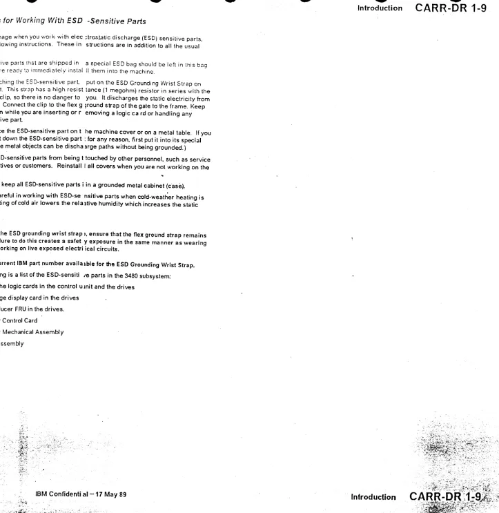
Flgur. 1. ESC Groundlnll Wrltt Strap
3480 MI EC336396
e
CopytigMI IBM Corp. 1984. 1985. 198e lieTJ
:}
'"
l
,... ,,J
:)
Instructions for Working With ESD-Sensitive Parts
To prevent damage when you work with electrostatic discharge (ESO) sensitive parts, observe the following instructions. These instructions are in addition to all the usual precautions.
• ESO-sensitive parts that are shipped in a special ESO bag should be left In this bag until you are ready to Immediately Install them Into the machine.
• Before touching the ESD-sensltive part, put on the ESO Grounding Wrist Strap on either wrist. This strap has a high resistance (1 megohm) resistor In series with the grounding clip, so there Is no danger to you. It discharges the static electricity from your body. Connect the Clip to the flex ground strap of the gate to the frame. Keep the strap on while you are Inserting or removing a logic ca rd or handling any ESO-sensltive part.
• Do not place the ESO-sensltlve part on the machine cover or on a metal table. If you need to put down the ESD-sensltlve part for any reason, first put It Into Its special bag. (Large metal objects can be discharge paths without being grounded.) • Prevent ESO-sensitive parts from being touched by other personnel, such as service
representatives or customers. Reinstall all covers when you are not working on the machine.
• If possible, keep all ESO-sensitive parts In a grounded metal cabinet (case). • Be extra careful In working with ESO-sensltlve parts when cold-weather heating Is
used. Heating of cold air lowers the relative humidity which Increases the static electricity.
CAUTION
When wearing the ESC grounding wrist strap, ensure that the flex ground strap remains connected. Failure to do this creates a safety exposure In the same manner as wearing Jewelry while working on live exposed electrical circuits.
Use the most current IBM part number available for the ESC Grounding Wrist Strap. • The following Is a list of the ESO-sensltlve parts In the 3480 subsystem:
All of the logic cards In the control unit and the drives Message display card In the drives
Transducer FRU In the drives.
1
I
:J
Introduction
CARR-DR 1-9
Introduction
CARR-DR 1-9
' l
l
< \.... ,
IntroductCt
o
o
This section contains the removal and replacement procedures for all Field Repl;J:eable Units (FRUs) in the 3480 Tape Subsystem. Checks and adjustment procedures are also included.
Carr Layout
CARR-DR pages 1-1 :hrough '-5 (in volume A03) contain a complete FRU lisl for Uw
conlrol unit and tape unit. An error code or FRU numoer Ihat is displayed on the
Maintenance Device (MD) operator panel will make reference 10 Ihis FRU lisl. The corresponding procedure should be performed. The FRU removal procedure isgiven first and the FRU replacement procedure immediately follows for the same FRU. All procedures are shown in a step by step method with keyed reference to views.
Common Procedures
Frocedures for cover removal and replacement. are given on CARR-DR
2-1
through CARR-DR2-6.
You will be sent to these common procedures by the FRU' removal and replacement procedures.Read through the complete procedure before performing it and give atlention to caution and danger notes.
Figure 1. ESD Grounding Wrist Strap
3480 MI EC A57723
c COPY';VM leM Corp. 1HZ. 19U
o
o
o
Instructions for Working
With
ESD -SensiUve Paris
To prevent damage when you WOI k with elec ;trost,atic discharge (ESD) sensitive parts.
observe the following instruclions. These in structions are in addition to all the usual precautions.
ESD-sensitive parts that are shipped in a special ESD bag should be left in Ihis baa until vou are ready:o immediately instal II them into the machine. -Before touching the ESD-sensitive parl put on the ESD Grounding Wrist Strap on either wrist. This strap has a high resist tance (1 megohm) resistor in series with the grounding clip. so there is no danger to you. It discharges the static electricity from your body. Connect the clip to the flex g ~round strap of the gate to the frame. Keep the strap on while you are inserting or removing a logic ca rd or handling any ESD-sensitive parl
Do not place the ESD-sensitive part on t he machine cover or on a metal table. If you need to put down the ESD-sensitive part: for any reason, first put it into its special bag. (large metal objects can be discha lIrge paths without being grounded.)
Prevent ESD-sensitive parts from being t touched by other personnel, such as service representatives or customers. Reinstall I all covers when you are not working on the machine.
If possible, keep all ESD-sensitive parts i in a grounded metal cabinet (c·ase). Be extra careful in working with ESD-se nsitive parts when cold-weather heating is used. Heating of cold air lowers the rei a 3tive humidity which increases the static electricity.
CAUTION:
When wearing the ESD grounding wrist strap I, ensure that the flex ground strap remains connected. Failure to do this creates a safet y exposure in the same manner as wearing jewelry while working on live exposed electri ical circuits.
Use the most current IBM part number availalble for the ESD Grounding Wrist Strap. The following is a list of the ESD-sensiti Ie parts in the 3480 subsystem:
All of the logic cards in the control u mit and the drives Message display card in the drives
Transducer FRU in the drives. loader Control Card
loader Mechanical Assembly load Assembly
IBM Conftdential-17 May 89
o
o
o
--Introduction
CARR-DR 1-9
[image:19.1224.478.1201.37.780.2]o
o
Tape Unit Cover Removal Procedure
Tape Unit With BM 6460006 (see
CARR-DR 9)
This page contains the steps needed to remove any of the tape unit covers. The drive drawer safety cover is not included on this page, but can be found on CARR-DR 2-5.
Tape Unit Front and Rear Cover Removal
The tape unit front and rear covers are held on by two hinges. The front cover hinges are on the right side, the rear cover hinges are on the left. Latches hold both covers closed. To open the front cover, push on the left center to release the latch. To open the rear cover, insert a small screw driver into the slot in the right center of the cover and push to the left to release the latch.
1. Pull the cover open until the hinge pins
B
are accessible. 2. Remove the ground strap from the cover, if present. 3. While holding the cover, remove the hinge pins and thenremove the cover.
4. Return to the procedure that sent you here.
3480 MI EC336395
'~Copynghl IBM Corp. 1984. 1985. 1986
c
c
Tape Unit Side Cover Removal
The last tape unit in a string of drives will have a cover on the right side. The other tape units do not have side covers. The tape unit side cover is held at the top by two cradle-like brackets
EI
attached to the tape unit frame. The bottom of the cover is held in place by a latch assemblyII.
1. To open the side cover, in~rt a small screw driver into the slot in the bottom center of the cover and push upward to release the latch.
2. Pull the bottom of the cover away from the tape unit, then lift the cover straight up and out of the