GA27-2890-4
File No. S360/S370/S3-09
Systems
-- -- -- --
-
--
--
-
---- ----
-
-Systems
GA27-2890-4
File No. S360/S370/S3-09
IBM 3270
Information Display System
3278 Display Station
Operator's Guide
- - . .
-
--- --- --- --- ---
- - - - . -
-
-
--..--- . .
----
-
-
---- ---- _
...
----_.-Fifth Edition (February 1984)
This is a reprint of GA27-2890-3 incorporating changes released in the following Technical Newsletters:
GN31-1259 (dated 14 November 1980) GN31-1428 (dated 29 April 1983)
Changes are periodically made to the information herein; before using this publication, refer to the latest IBM System/360 Bibliography. GA22·6822 and the IBM System/370 and 4300 Processors Bibliography. GC20-0001, for the editions that are applicable and current.
References in this publication to IBM products, programs, or services do not imply that IBM intends to make these available in all countries in which IBM operates.
Publications are not stocked at the address given below. Requests for copies of IBM publications should be made to your IBM representative or to the IBM branch office serving your locality.
A form for readers' comments has been provided at the back of this publication. If the form has been removed, address comments to IBM Corporation, Department 52Q. Neighborhood Road. Kingston. N.Y. 12401. IBM may use or distribute whatever information you supply in any way it believes appropriate without incurring any obligation to you.
Preface
This guide is written for persons who will be operating the IBM 3278 Display Station attached to a 3274 Control Unit or to a 3276 Coptrol Unit Display Station. If your 3278 Display Station is attached to a control unit or to an adapter other than a 3274 or a 3276, some operations and/or indica-tors may be different from those described in this guide. The operator should refer to the appropriate appendix for a description of these differences.
For information about the operation of the 3274 Control Unit, the 3276 Control Unit Display Station, the 3287 Printer, and the 3289 Line Printer, refer to the following pUblications:
• IBM 3270 Information Display System: 3274 Control Unit Operator's Guide, GA23-0023
• IBM 3270 Information Display System: 3276 Control Unit Display Station Operator's Guide, GA18-2040
• IBM 3287 Printer Operator's Guide, GA27-3150
• IBM 3289 Line Printer Operator's Guide, GA27-3147
For information about the setup of the 3274 ModellC, 3276,3278,3287, and 3289, refer to the following documents:
• IBM 3270 Information Display System: 3274 Control Unit Planning, Setup, and Customizing Guide, GA27-2827
• IBM 3270 Information Display System: 3276 Control Unit Display Station Planning and Setup Guide, GAl 8·2041
• IBM 3274 Control Unit ModellC Setup Instructions, GA27·2855
• IBM 3276 Control Unit Display Station Setup Instructions, GA18·2017
• IBM 3278 Display Station Setup Instructions, GA27-2838
• IBM 3287 Printer Setup Instructions, GA27·3152
• IBM 3289 Line Printer Setup Instructions, GA27-3140
The keyboards illustrated in this manual are U.S. and Canadian French keyboards. For information concerning other keyboard languages, refer to IBM 3270 Information Display System: Character Set Reference, GA27-2837.
While IBM makes available many basic functions, the user chooses those he will utilize and in what manner. It is the responsibility of the user to establish and maintain appropriate operating procedures for the equipment.
Some of the units, devices, options, and features described in this manual may not be available in every locale. Ask your local IBM marketing representative for information about product availability.
Contents
Chapter I. Introduction 1-1 !-'irst Word s to the Operator 1-3 Data Processing 1-4
The Data Processing System 1-4
Chapter 2. Controls and Indicators 2-1 3278 Quick Reference 2-2
Introduction to 3278 Operation 2-6 3278 Operator Controls 2-8 The Display Image 2-11
Cursor 2-15
Cursor Wrap 2-16
3278 Operator Panel Lights 2-18 Operator Information Area 2-19 Cleaning Procedures 2-28
Chapter 3. Keyboards 3-1
Introduction 3-3
Typewriter Keyboard 3-7
Data Entry Keyboard 3-17
Similar Keys on Typewriter and Data Entry Keyboards
Attribute Select Keyboards 3-46
Chapter 4. Features for the 3278 4-1 Selector Light Pen Feature 4-3
3-25
Magnetic Slot Reader and Magnetic Hand Scanner Accessories 4-6
Security Keylock Feature 4-9
Audible Alarm Feature 4-10
Numeric Lock Feature 4-11
3278 Switch Control Unit Feature 4-12
3278 APL/Text Feature 4-13
X.21 Switched Networks Feature 4-28
Chapter 5. Important Differences between the 3275/3277 and
the 3278 5-1
Introduction 5-3
Screen Character Capacities 5-4
3278 Operator Controls 5-5
3278 Display Image 5-7
3278 Operator Information Area 5-8
3278 Keyboards 5-9
Selector Light Pen Feature 5-16
Magnetic Slot Reader Accessory 5-16
Appendix A. Sample Problem Report Form A-I
Appendix B. 3278 Display Station Attached to a 4331 Processor B-1
Index X-I
Figures
1-1. 2-1. 2-2. 2-3. 24. 2-5. 2-6. 2-7. 2-8. 2-9. 3-1. 3-2. 3-3. 34. 3-5. 3-6. 3-7. 3-8. 3-9. 3-10. 3-11. 3-12. 3-13. 3-14. 3-15. 3-16. 3-17. 3-18. 3-19. 3-20.All data processing systems have Input, Processing and Output sections. 1-5
IBM 3278 Display Station 2-7
When the horizontal bar and the Ready indicator appear, your display station is warmed up and ready to
operate. 2-8
The image on your screen might look like this. 2-12 Bank checks have a standard arrangement. 2-12 The normal cursor looks like an underscore. 2-15 The alternate cursor is a reversed character image. 2-16 The cursor wraps when you move it off any edge of the display area. 2-17
3278 Operator Panel Lights 2-18 Operator Information Area Layout 2-19 3278 Problem Determination Guide Access 34 Typewriter Keyboard 3-5
Data Entry Keyboard 3-5
Data Entry-Keypunch Layout Keyboard 3-5 Attribute Select Typewriter Keyboard 3-6 Attribute Select Typewriter/APL Keyboard 3-6 Attribute Select Overlay Keyboard 3-6 Typamatic (Repeat-Action) Keys 3-8 Alphabet Keys 3-9
Numeric Keys 3-10
Some symbols are located on numeric keys. 3-11 Some keys contain only symbols and punctuation marks. 3-12
PF1-PF12 Keys 3-14
Typamatic (Repeat-Action) Keys 3-18 Alphabet Keys 3-20
Symbol and Punctuation Mark Keys 3-21 Program Function (PF) Keys 3-24 Spacebar 3-25
Cursor Control Keys 3-25 New Line Key Operations 3-27
3-21. 3-22. 3-23. 3-24. 3-25. 3-26. 3-27. 3-28. 3-29. 4-1. 4-2. 4-3. 44. 4-5. 4-6. 4-7. 4-8. 4-9. 4-10. 4-11. 4-12. 5-1. 5-2. 5-3. 54. 5-5. 5-6. 5-7. 5-8.
Tab Key Operations 3-28 Back Tab Key Operation 3-29
CURSR SEL Key Selectable Fields 3-33
Use the Insert key to insert missing information. 341 Insert Mode Example 342
Canadian-French Dead Keys (Typewriter Keyboard) 344 Canadian-French Dead Keys (Data Entry Keyboard) 344 Attribute Select Keys PFI-PFI2 348
Attribute Select Keys PF13-PF24 349 3278 Selector Light Pen 4-3
When the selector light pen is being used, correct positioning of the tip of the pen is important. 4-3
Designator characters tell you about the data on your screen. 44
Magnetic Slot Reader 4-6 Magnetic Hand Scanner 4-6
Only authorized operators may use a display station that has a security key lock. 4-9
Control Unit Selector Switch 4-12 APL/Text Character Set 4-14 Typewriter/APL Keyboard 4-15
Graphic Characters Entered by the Typewriter/APL Keyboard (2 Parts) 4-17
Typewriter/Text Keyboard 4-20
Graphic Characters Entered by the Typewriter/Text Keyboard (2 Parts) 4-22
IBM 3278 Display Station 5-3 3278 Operator Controls and Lights 5-5
The alternate cursor is a reversed character image. 5-7 3278 Typewriter Keyboard 5-9
3278 Data Entry Keyboard 5-9
Chapter 1. Introduction
Contents 1-1
First Words to the Operator 1-3 Data Processing 1-4
The Data Processing System 1-4
Input Section 1-6 Processing Section 1-6
Output Section 1-7
First Words to the Operator
This Operator's Guide provides operating instructions and operating tips for the
iBM 3278 Display Station.
As a 3278 Display Station operator, you may operate a keyboard, an operator
identification card reader, a magnetic slot reader, a magnetic hand scanner, a personal computer, or a selector light pen, depending on the equipment needs of your organization. The purpose of this manual is to help you prepare for these variolls operating tasks.
Readers of this manual need no previous knowledge of host systems, display system equipment, or data processing. General background information is provided to introduce you to data processing and host systems. If you have
no experience in this area, begin by reading the "Data Processing" and "The Data Processing System" sections of this chapter.
The other chapters of this manual discuss in detail the operator controls, indi-cators, keys, and typical operating procedures for the 3278 Display Station.
The 3278 controls and indicators are discussed in Chapter 2.
Instructions for keyboard use are given in Chapter 3.
I nstructions for using the selector light pen, security keylock, magnetic slot reader, magnetic hand scanner, and other 3278 features are given in Chapter 4.
instructions for using the IBM 3270 Personal Computer Attachment are given in the IBAl Personal Computer 3270 Attachment User's Guide.
If you are an experienced 3275 or 3277 operator and you are interested in the differences between the 3275/3277 and the 3278, refer to Chapter 5.
If you are interested in the operation of an IBM 3274 Control Unit, refer to
the IB!'y[ 3270 Information Display System: 3274 Control Unit Operator's
Guide, GA23-0023.
I f you are interested in the operation of an IBM 3276 Control Unit Display Station, refer to the IBM 3270 Information Display System: 3276 Control
Unit Display Station Operator's Guide, GA18-2040-0.
Data Processing
Following is a brief description of data processing and of the part you and your display system equipment play in the data processing of your organization.
First, you must understand that the "data" in "data processing" refers to all the information or records required by your organization to conduct its business. This is a lot of information to think about, so, for our discussion, let us con· sider only the data required for payroll administration, a common part of all business. The data (information) required to perform this function includes the mimes of all employees, the number of hours each employee worked, his or her rate of pay, the number of overtime hours he or she worked (if any), the amount of money to be withheld, and all other facts needed to pay everyone the correct amount.
The "processing" in "data processing" refers to all the work involved in accom· plishing a particular data processing job. In a data processing "payroll" job, the processing involves providing the host system with the required data, determining (with the data) each employee's paycheck amount, printing all the checks, and updating the records.
Putting the two together, then, data processing is the performance of jobs or tasks by processing the required data.
Although data processing has always been
a
major part of running an organiza· tion, it has not always been called data processing. Before the development of the data processing system, almost all processing of data was done by hand. Today, most of it is done by data processing systems and in much less time than before.The Data Processing System
You will be operating a machine that is part of your organization's data process· ing system. To give you some knowledge of the other machines in that system, we will now examine the different groups of machines that make up a typical data processing system. The points discussed will hol4 true even though some of the machines that are mentioned may not be included in all data processing systems.
INPUT
1
j
T
1
PROCESSING
r
!
[image:12.613.67.549.61.540.2]OUTPUT
Figure 1-1. All data processing systems have 'Input, Processing, and Output sections.
Input Section
An input machine is any machine that provides for entry of outside data (infor-mation) into the host system. This definition can be used to determine if a machine is part of the input section of a data processing system. Input machines may be located at the host system site or at remote locations where they com-municate with the host system over telephone lines.
Most of the data needed to perform a job is produced by people. As a result, it is handwritten or typed on one kind of form or another. A host system cannot process this data. These forms are the source of the input data to be entered into the host system. Thus, the data at this point is called source data.
Part of the job of the machines in the input section of a data processing system is the translation of the source data into a form that the host system can under-stand. These machines translate the source data and record it in the host system's language; also, and perhaps most important, they enter it into the data processing system. As you type from the source documents, you and your 3270 display station will be performing this type of work. Note that the selector light pen, operator identification card reader, and magnetic slot reader are also input devices which assist you in communicating with the host system.
The importance of the input section in a data processing system cannot be stressed enough. You may be the best typist in the world, but, if you are given inaccurate information to type, your completed typing will not be of much value. The same is true of any data processing system. The best host system in the world can pro-duce results (output) of value only with accurate input data.
The machines that make up the input section, though small compared with some of those in the processing section, are vital to the success of the data processing system. Keypunches and card readers, typewriter terminals, and display stations are some types of input machines.
Processing Section
The host system site, as you might guess, is where the host system is located. Once the system has all the information it needs for the intended job, the required work must be performed. This is done at the host system site by the group of machines that make up the processing section of a data processing system.
Several types of machines at the host system site process the data. Working together, they are used to sort the data, test it, perform computations on it, and otherwise use it to accomplish the assigned job.
Note that we said these machines are used to process data. The host system pro-gram uses the host system's capabilities.
Output Section
Mter the work has been completed, the results must be made available. This is done by the machines that make up the output section of a data processing system.
Output from a data processing system can be in various forms. Printers, tape drives, card punches, and display stations are only a few examples of output machines; the most widely used is the printer. Printers can provide printed checks for payroll jobs, printed bills for customer billing jobs, printed reports, or any number of other types of output for all kinds of jobs.
Chapter 2. Controls and Indicators
Contents 2-1
3278 Quick Reference 2-2 Introduction to 3278 Operation 2-6 3278 Operator Controls 2-8
On/Off (
110 )
Swit<;h 2-8~ Brightness Control 2-9 () Contrast Control 2-9
.R. Audible Alarm Volume Control 2-9 Normal/Test Switch 2-10
Dual Case/Mono Case (A,a/ A) Switch 2-10 Video Test Switch 2-10
The Display Image 2-11
Fields and Formatted Displays 2-13 Input Fields 2-13
Numeric Fields 2-14
High-Intensity Data 2-14 Protected Data 2-14 Nondisplay Fields 2-15 Cursor 2-15
Cursor Wrap 2-16
3278 Operator Panel Lights 2-18 Operator Information Area 2-19
Readiness and System Connection 2-20 Do Not Enter (Input Inhibited) 2-21 Reminders 2-26
Shifts and Modes 2-27 Highlighting 2-27 Printer Status 2-28 Oeaning Procedures 2-29
3278 Quick Reference
Switches, Controls, and Lights
light 2
light1
~
~
On/Off (
light 3 ~
1/0
I
SWitch-1l~ ~
~
4
(A,a/A) SwitchI
Dual/ Mono Case6
'1 -
NormalfTest Switch!f
l
~~~~~Ie
Alarm~meControl
fit" .
Security Keylockf\
Contrast Control.J
Brightness Control~\--=-~---f
---Operator Information Area
Operator Information Area Layout
Shifts and Modes
Readiness and Do Not Enter Reminders Programmed Symbols Selection
System Connection (Input Inhibited) Highlighting
Operator I nformation Area Symbols and Messages
Note: For a 3278 not attached to a 3274 or to a 3276, these symbols and
messages and/or their meanings may be different from those described here. Refer to the appropriate appendix for a description of these differences.
• Readiness and System Connection Symbols
Location 1 H1and~ - Means the 3274 ( 111 ) or 3276 ( ~ ) Control Unit is working (ready).
Printer Status
Location 2
Location 3
l1andA-I
Means the control unit is connected (online) to the host system under rules A (
..a )
or rules B ( ]. 'j, Your display station is working with your job (application program).Location 3
Location 3
Locations 3-6
00
~
TEST
Your display station is connected to the s.ystem operator (control program).
Your display station is connected to the host system but is not connected to your application program or the control program.
~278
Quick Reference
• Do Not Enter (Input Inhibited) Messages
>< .::, .. ::.
><
?+
Time is required for the host system to perform a function. Wait. Press RESET; then try the operation again.
The host system has locked your keyboard. Look for a message. Wait or RESET.
><
S"{:~;TEt'''l><
><
><
><
)( )(><
)( )( )( )( )(7.:>
7.:t··lUr·'·l
*u
'?
-f
~
nn
and
~
nnn
~,"-nn and ~,,-nnn
PROGnn
andPROGnnn
Go elsewhere on the screen to take that action. RESET. Move the cursor or take other action. You have tried to insert more data than this field can hold. RESET. Correct the entry. You should enter only numerals in this field. RESET. Then enter only numerals. Only certain numerals can be entered here. RESET.
The function you requested is not available.
Your display station is not operating properly. RESET. If problem persists, refer to the display station or control unit Problem Determination Guide to determine the appropriate action.
There is a problem with the communication line !between the control unit and the host system. RESET. If problem persists, refer to the display station or control unit Problem Determination Guide to determine the appropriate action.
The control unit detected a programming error in the data it received from the host system. RESET. If problem persists, refer to the display station or control unit Problem Determination Guide to determine the appropriate action.
The printer connected to your display station is busy. If ~ is displayed on the right, the printer is busy printing your work. Wait for the operation to finish, or press DEV CNCL to cancel a pending print operation. (If the print operation has started, the operation cannot be canceled by the DEV CNCL key.)
><
C}-CJ.:):: ..
:»
)( ~
Same as above except more time is anticipated before your operation is accepted.
The printer assigned to your display station is not working. If ~ is displayed on the right, the printer stopped while printing your work. Wait or press DEV CNCL to cancel the print operation.
><
)(X
)( )(><
)( )( )(><
)( )(7.:><
0-.1 -¥- ,-, ... 8:··7.:" +'?
7.: ... +'?
7.: ... +'?
7.:'"+'?
7.: +?
"-:S
0+-00
-f.xX
~2>:.:>:;
}
You are not aut:,orized to do that function. RESET.
Security key lock is off. Keyboard can be unlocked only by key.
That magnetic stripe card cannot be used in this operation. RESET. Try a different card, or request help.
You have entered an invalid accent and character combination. RESET. Then rekey both the accent -and the character. (Canadian French keyboard only.)
The symbol key you pressed is not available. RESET.
A message from the control operator was received and rejected. RESET The application program will not allow you to make that selection. Your display station is not configured for that selection .
• Reminders
~nn
-
The communication link connecting your control unit to the host system is producing errors.and
~nnn
Cl+-{!] - Reserved for future use. Ignore .
• Shifts and Modes Messages Programmed Symbols Selection
SO No Programmed Symbols Selected
PSA Programmed Symbols - Set A
PS'B Programmed Symbols - Set B
PSC Programmed Symbols - Set C
PSD Programmed Symbols - Set D
PSE Programmed Symbols - Set E
PSF Programmed Symbols - Set F
*
*
You have selected a Programmed Symbol Set*
~ Field Inherit for Programmed Symbols*If neither symbol is present, the selection you made is not available at your display station.
3278 Quick Reference
NUM
APL
TEXT
1l'
I"-ALPHA
- The keyboard is in Numeric Mode. Only 0 through 9, period (.), minus (-), and DUP will be accepted.
- The keyboard is in APL Mode.
- The keyboard is in TEXT Mode.
- The keyboard is in upshift.
- The display station is in Insert Mode.
- The keyboard is in Alpha Shift (Data Entry Keyboard only)
- Character Highlighting
a
Normal character selectedBlinking character selected Reverse character selected Underscore character selected
Field inherit for character highlighting
- You have selected a Programmed Symbol Set .
• Printer Status Messages
r::J---C:]__ - When you are changing the Printer ID/Class, the two numerals you key are displayed in the underlined
o---..nn
·~nn
locations of the message.
- Your display station is authorized to use Printer ID/Class nn.
- The selected printer is printing your work.
- The printer stopped while printing your work.
- Your printer assignment has changed.
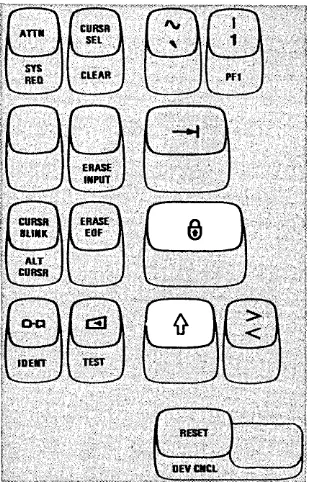
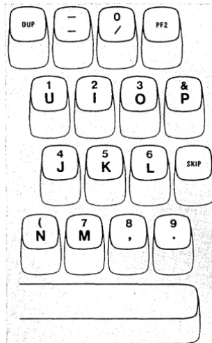
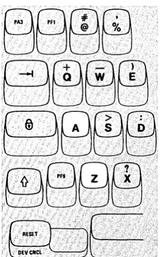
KEYBOARD
""m888EfBBBB8B8Ed-~~
~~l~' .,·1·~~E~3f3Eag88B888888
8[9
_:·~~E~_~~"n
... '
~~
___ ,,' ,n.,
,~~_~_~~.~~~~~i
___
j
*Typewriterkeyboard only.
The keys highlighted above are typamatic keys. This means that they have the ability to repeat their character or function when held down. They are:
...
~....
D
•
+
•
..
...
...
All Alphabetic, Numeric, Symbol, and Punctuation Mark Keys, and the following keys:
Tab ·New Line
Back Tab Home Backspace Move cursor up Move cursor down Move cursor left
3278 Quick Reference
+~ Double-speed move cursor right
SKIP (Same as Tab) Spacebar
ENTER PFl-·PF12
RESET (Data Entry - Keypunch Layout Keyboard)
Some of the function keys are:
CURSR SEL Selects fields for processing. Cursor must be in a field that your application has designated for
cursor selection. CLEAR
ERASE INPUT ERASE EOF CURSR BLINK ALTCURSR
Cl-Cl
Erases display and signals the host system that a clear action occurred.
Erases all input fields and moves the cursor to the first input character position on the screen. Erases the input field from the cursor to the end of the field. The cursor does not move. Causes cursor to blink or not blink.
Selects between the two forms of cursor (underline and reverse character image). Print key. Sends data from the display station to the selected printer.
IDENT Signals that the next two numbers will be the selected printer I D code. The I D is displayed in the
Operator Information Area. The IDENT key is also used to display the new ID when your printer assignment is changed.
Turns the keyboard clicker on or off.
c::!l
TEST Used to run special problem determination functions. Refer to your display station's Problem
Determination Guide.
Cancels a pending print request to the printer. DEV CNCL
~
I'
Insert key. Allows character insertion in an input field. To end Insert Mode, press RESET. Delete key. Deletes the character at the cursor position in an input field.
How-to-Do References:
• Insert character(s) into a displayed area - see ~ key description in Chapter 3.
• Remove (delete) character(s) from a displayed area - see
;l
key description in Chapter 3.• Enter alphabetic character(s) into a Numeric field - see "Numeric Lock Feature" in Chapter 4. • Select a selectable field with the CURSR SEL key - see CURSR SEL key description in Chapter 3. • Request or change the printer ID - see IDENT key description in Chapter 3.
• Cause the information on your screen to be printed - see Cl-Cl key description in Chapter 3.
• Cause the cursor to blink on and off - see CU RSR B LI N K key description in Chapter 3. • Select the alternate cursor - see AL T CU RSR key description in Chapter 3.
• Cancel a print operation - see DEV CNCL key description in Chapter 3. • Turn the keyboard clicker on or off - see
c:iJ
key description in Chapter 3. • Use a selector light pen - see "Selector Light Pen Feature" in Chapter 4.• Use a magnetic slot reader or a magnetic hand scanner - see "Magnetic Slot Reader and Magnetic Hand Scanner Accessories" in Chapter 4.
• Adjust the audible alarm volume - see "Audible Alarm Feature" in Chapter 4. • Use highlighting
- character reversal - see "Attribute Selection Keys" in Chapter 3. - character blinking - see "Attribute Selection Keys" in Chapter 3. - character underscoring - see "Attribute Selection Keys" in Chapter 3.
• Use the programmed symbol set selection keys - see "Attribute Selection Keys" in Chapter 3. • Use the Field Inherit Keys - see "Attribute Selection Keys" in Chapter 3.
Something Is Wrong
Is this it? . . . . . . . . Have you tried this?
Display station will not turn on. Make sure the power cord is plugged into the wall outlet.
No clicks when keys are pressed. Is Do Not Enter ( )( ) symbol on? RESET key turns it off.
Is Do Not Enter ( )( ) symbol off? Check condition of Click (
c:IJ )
key.For more information on troubles, refer to the 3278 Problem Determination Guide.
Introduction to 3278 Operation
If possible, sit at a display station as you read thjs part of the manual so that you can use the switches and keys as you read about them. If your display station has a keyboard attached and if some point is not clear as you read, pause for a moment to press the key and watch the result. Keep in mind, however, that the purpose of some of the keys is to notify the host system that your display station needs service by the program. Pressing any of these keys when the host system is ready interrupts the program. In case you do not have a keyboard provided with your display station, you will only be required to make initial adjustments to the display station (as explained in this section).
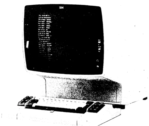
The IBM 3278 Display Station is shown in Figure 2-1.
Your 3278 Display Station will have one of the following six screen formats: 480 characters (12 lines of 40 characters each), 960 characters (I2 lines of 80 characters each), 1920 characters (24 lines of 80 characters each), 2560 characters (32 lines of 80 characters each), 3440 characters (43 lines of 80 characters each), or 3564 characters (271ines of 132 characters each).
If your organization uses both 3275/3277 and 3278 Display Stations, you may work with programs that use both groups of display stations. These programs can format the screen of your 3278 in the same way that they format a 3275 or 3277 screen. The 3275 and the 3277, however, have 480- and 1920-character screen formats.
The On/Off (
I /
0 )
switch is located near the screen's lower-left corner; the screen brightness control-d-
and the contrast control ( ) are located near the screen's lower-right corner. The brightness and contrast controls allow you to adjust the display to a comfortable viewing level.We will begin by turning on the display station. We will then proceed from adjusting and interpreting the display image, through explaining the indicators, and, if your display uses a keyboard, to understanding all the keys on the keyboard.
Figure 2-1. IBM 3278 Display Station
[image:22.615.59.349.196.442.2]3278 Operator Controls
On/Off(
I/O )
Switch
.
Press the top portion (
m )
of the On/Off switch shown at the right to turn on your display station. Light 3 and Light 1 (see Figure 2-2) should have turned on when you pressed the On/Off switch. A delay of a few seconds allows the machine to warm up. After this delay, (1) Light 2 turns on, (2) a short horizon-tal bar (cursor) appears in the upper-left portion of the screen under the first position in line 1, (3) a horizontal line appears across the lower portion of the screen, and (4) a Ready symbol (see 3278 Quick Reference, Readiness and System Connection Symbols) appears in the lower-left portion of the screen (Operator Information Area). See Figure 2-2.If your display station has the Security Keylock feature (described in Chapter 4) and the keylock is locked, the )( .:..., (Security Key) symbol appears at the bottom of the screen to tell you to insert the security key and turn off the lock (turn key clockwise). When you leave your display station, turn on the lock (turn key counterclockwise) and remove the key.
Note: The keylock turns 90° (vertical to horizontal position) when you turn
the key.
When you are ready to turn off your display station, press the bottom portion
<101
)of the On/Off switch.Light 1
Ready Symbol (when attached to a 3276)
,
~I
-
-10"
.Normal/Test Switch
Audible Alarm Volume Control
-¢-
Brightness Control
You can adjust the brightness of the characters displayed on the screen by turn-ing the brightness control
U
knob to the left or to the right. Turning itto the right makes the display image brighter; to the left, dimmer. Experiment with this control until you find the setting that is most convenient and comfort-able for your viewing.
This control also has a test position. When the control knob is turned fully clock-wise beyond the first stop and held, the screen becomes very bright.
( )
Contrast Control
The contrast control ( ) is another aid in adjusting your display for comfort-able viewing. If your organization uses two intensity levels to display characters (explained later in this chapter under the heading "High Intensity Data"), the contrast control varies the difference between these two levels. You may have to experiment with this control until you find the contrast level that satisfies you.
i l
Audible Alarm Volume Control
If your display station has the Audible Alarm feature (described in Chapter 4) installed, the volume control
R
for the audible alarm is located at theoutside of and behind the screen contrast control. Turning this control clockwise will increase the sound level; turning the control counterclockwise will decrease the sound level. If you want to test or adjust the audible alarm, refer to the Audible Alarm feature description in Chapter 4.
Normal/Test Switch
When you are operating the display station, this switch will be in the Normal position.
You will use the Test position of this switch when you have a problem with the machine and you perform the problem determination procedures. When you place the switch in the Test position, you can perform the tests that are described in Section 3 of the 3278 Problem Determination Guide.
Dual Case/Mono Case (A,a/A) Switch
You can use this switch to cause your display station to display (l) only upper-case alphabetic characters or (2) both uppercase and lowercase characters. To select only uppercase characters, set the switch to A; to select uppercase and lowercase characters, set the switch to A,a.
However, the position of this switch does not determine whether uppercase or lowercase alphabetic characters are sent to the host system. For example, if the switch is set to A and you enter a lowercase e character, an uppercase E char-acter is displayed on the screen; however, when the charchar-acter is sent to the host system, the code for a lowercase e character is sent.
Video Test Switch
If your display station has the IBM 3270 Personal Computer Attachment installed, the Video Test switch is located in a panel on the back of the display. This switch does not affect the display and can be in any position during display operation.
You will use the Test Mono and Test Color positions of the switch when you have a display station problem and are performing problem determination.
Normal
8
TestA,a
[3
A
Test Mono
8
NormalThe Display Image
To make your display station ready for operation, perform the following:
Note: If the display station screen is dirty, refer to "Qeaning Procedures" at
the end of this chapter.
1. Use the On/Off ( I / 0 ) switch to turn the display station on.
2. If the display station has the Security Keylock feature, insert the security key into the lock and turn the key clockwise. (Refer to Chapter 4 for a description of the Security Keylock feature.)
3. Adjust the brightness and contrast controls.
4. If t}1e display station has the Audible Alarm feature, adjust the audible alarm volume control by using the procedure in the Chapter 4 Audible Alarm feature description.
If your display station has a keyboard, skip over the next paragraph and continue reading this section.
If your 3278 does not have a keyboard, selector light pen, magnetic slot reader, or magnetic hand scanner attached, operation is controlled by the program, and you may monitor information displayed on the screen. If your 3278 does not have a keyboard, selector light pen, magnetic slot reader, or magnetic hand scanner, you should now read about the lights and the Operator Information Area on your 3278, starting with "3278 Operator Panel lights." If your 3278 does not have a keyboard, but does have a selector light pen, a magnetic slot reader, or a magnetic hand scanner, read about the lights and the Operator Information Area, starting with "3278 Operator Panel lights," and then refer to Chapter 4 for a description of selector light pen or magnetic slot read operation.
Before we talk about the keyboard, there are some things you shoulq know about your display screen.
As we have said before, the 3278 Display Station can be used by many different organizations, all with very different kinds of jobs to be done. Even within one organization, there are m'any different applications for 3278 displays. Today's host systems are capable of process~g many different jobs at the same time. Therefore, it is possible that you could be working on one jqb ~hile the operator next to you is doing completely different and unrelated work. Tn.e images on your two screens woulH probably be completely different .
• " ; f
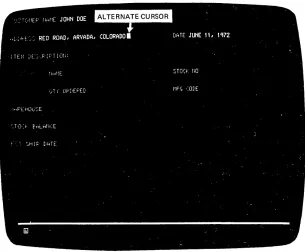
Figure 2-3 is a typical display image; you will be referred to t4is image in some of the discussions that follow. Keep in mind that this example is only one of many possible display images. Your organization may not even require this type of image. The references made to it, however, apply to all images.
Figure 2-3 .. The image on your screen might look like this.
As you can see, the display image looks much like information typed on a sheet of paper. Notice, too, that the organization and content of this form are no different from the organization and content of handwritten and hand-processed
documen~s. The same type of information is always recorded in the same areas. This is true of all documents, as can be seen by examining the arrangement of a standard bank check (Figure 2-4).
3'
__________________ 10 _ _
PAYTOTDE ORnER OF. _ _ _ _ _ _ _ _ _ _ _ _ _ _ _ _ _ _ _ _ _ _ _ _ _ _ _ _ _ _ _ ..u. o::!' ______ _
_ _ _ _ _ _ _ _ _ _ _ _ _ _ _ _ _ _ _ _ _ _ _ _ _ _ _ _ _ _ _ _ _ _ _ _ _ _ _ _ _ _ _ .:II)'Ull.I' ... R~
Figure 2-4. Bank checks have a standard arrangement.
Fields and Formatted Displays
The various areas of bank checks that always contain the same type of informa-tion are called "fields" in data-processing language, for example, the "date" field or the "signature" field. Most documents to be entered into a host system will be organized by fields.
This practice of standardizing the arrangement of data originated because the person using the information could do his or her job much faster knowing that one type of data would appear at the same location on every document.
When a display station screen is divided into fields, it makes working with the display station quicker and easier for both the display station operator and the host system program. The application program divides the screen into fields and establishes the rules as to what each field will contain. The program then knows that the same type of information will always be displayed in the same location. Knowing this, the program can process the data from the screen much more quickly. The operator can also perform his or her job more efficiently having this information.
When a screen is divided into fields, it is known as a formatted screen. A screen that the program has not divided into fields is known as an unformatted screen. Eachjob that you work on could use a different format or none at all; therefore, you may be working with both fonnatted and unformatted screens.
Input Fields
You may see two types of fields on your screen. One is primarily used by the program to send you messages, instructions, and headings; you cannot key data into this type of field. All of your entries will be into the other type. For this reason, in the remainder of this manual, fields that you can key data into will be referred to as input fields. Each application program user's guide should tell you which are the input fields for that particular job.
Once a field is assigned to one type of data in a job, those character positions should not be used for other data items in that job. For example, one field on the screen in Figure 2-3 is called "STOCK NO". That is the only type of infor-mation you will key into it. You will not, for instance, key the digits of an MFG CODE number into the STOCK NO field. (Otherwise, the display station key-board may stop functioning or a message may appear on the screen telling you of the error.)
There is no rule stating that fields must always be a certain length or that there will always be the same number of fields on the screen. The length of a field is normally arrived at by determining, from the type of information that will be entered in the field, the longest possible length of one entry. In many cases, this is known. For example, all Stock numbers could be the same length, 9 digits; therefore, the field for Stock numbers is 9 character spaces long. When the max-imum length is not known, as in a field marked for customer name, maxmax-imum length must be estimated by some method, and the field length must be set from that estimate.
The number and names of fields that you will see on your screen will depend on the job you are doing and the application program that is operating in the host system.
Numeric Fields
Fields that normally contain only numbers (Stock number, manufacturer's code number, etc.) are known as Numeric fields. Such fields are used in organizations whose jobs are largely of the data-entry type.
Entry of numeric data is made possible by use of a Data Entry keyboard (described in Chapter 3). When your screen is formatted by your user's program, the Data Entry keyboard automatically shifts to Upshift Mode and the
It
(upshift) symbol appears in the Operator Information Area when the cursor enters a numeric field. (If the Numeric Lock feature is installed in your keyboard, the NUM shift symbol appears in the Operator Information Area instead of theIt
symbol.) Therefore, if you have a Data Entry keyboard, numeric fields help to increase your operating speed.If you are using a Typewriter or Data Entry keyboard that has the Numeric Lock feature installed, the NUM shift message appears in the Operator Information Area when the cursor enters a Numeric field. When this occurs, the only keys that you can key into the Numeric field are the digits 0 through 9, period ( . ), minus ( - ), and the DUP key. Pressing any other key that can enter a display-able character turns on the Do Not Enter - Numeric Data Only
(><
*NUM)message in the Operator Information Area and disables your keyboard (keyboard either starts or stops clicking). For additional information concerning the Numeric Lock feature, refer to Chapter 4.
The user's program guide for the program that you are working with should designate which the numeric fields are.
Figure 2·5 shows two other features of the 3278 that you can expect to see often. The more apparent of these is called "High·Intensity Data."
High-Intensity Data
This feature of the 3278 allows the display of fields (selected by the application program) at.a brighter than normal intensity. Use of this feature makes the high-intensity fields stand out from the other fields displayed on the screen. Many companies make effective use of this feature by displaying the field names at normal intensity and the operator-keyed data at high intensity.
Protected Data
Not quite so obvious in the example in Figure 2-5 are the protected fields. They are the fields displayed at low intensity. We mentioned before that, in most jobs:, there will be some areas on the screen where you will not be able to type. You will not be able to change field names (titles), for instance. In Figure 2-5, STOCK NO is a field name and would probably be a protected field.
The protected·data feature aids your operation because you do not have to worry about making a mistake and destroying part of the data on your screen. A
>< ...
*....
(Go Elsewhere) message will come on in the Operator Infor-mation Area (bottom of screen) if you attempt to change (type over, erase, insert, or delete characters) any data in a protected field.The blank field directly following "STOCK NO" is the unprotected stock number input field. You would key stock numbers from your source document into this field.
Nondisplay Fields
This feature of the 3278 allows the program to cause the information in a field to be nondisplayable. An example of the use of a nondisplay field is using such a field for entry of your operator identification when you log on your display station. When you enter your operator identification into the nondisplay field, your operator identification remains secret, because it is not displayed on the screen.
The user's program guide for the program that you are working with should designate which fields on the screen are nondisplay fields.
Cursor
The cursor operation is an important operation for you to understand when you are working with the display image. You will find that the flexibility of the cursor makes operating a 3278 easier and more enjoyable than operating a type-writer or a keypunch. For example, moving the cursor is easier and faster than repositioning the carriage of a typewriter or transporting the card in a keypunch.
[image:30.612.72.375.315.561.2]Two types of cursors can be displayed on the screen of a 3278: the normal cursor and the alternate cursor. The normal cursor appears on the screen as an underline to the character position in which it is located (Figure 2-5).
Figure 2-5. The nonnal cursor looks like an underscore.
The alternate cursor is a reverse image of the character that is located in the same character position as the cursor (Figure 2-6). By using the ALT CURSR and CURSR BLINK keys (described in the keyboard sections), you can select either type of cursor and you can also make the cursor blink on and off continuously.
Figure 2-6. The alternate cursor is a reversed character image.
The cursor marks the position on the screen that the next character entered from the keyboard will occupy. It may be moved about freely on the screen, by use of certain keyboard keys, without interfering with other characters. You will also notice, when entering characters from the keyboard, that the cursor moves to the next available character position as each character is entered (except for Canadian French keyboard Dead Keys, as explained in the keyboard sections).
You may see the cursor apparently changing locations by itself. It can be moved about on your screen by the program, and when the cursor appears to be moving by itself the program is repositioning it for you.
Cursor Wrap
The cursor control keys are located on the keyboard and described in the key-board sections. They move the cursor in either the horizontal (left or right) or vertical (up or down) direction on the display station screen; the .... and ... (horizontal positioning) keys and the
+
and+
(vertical positioning) keys move the cursor one position at a time; the ... and ... (double-speed horizon-tal positioning) keys move the cursor two positions at a time. If you hold down the key that moves the cursor to the right, the cursor will move off the right side of the line and will reappear one line lower on the left side. This is called cursor wrap. In effect, the cursor wraps around behind the screen. It also wraps when moved to the left, and it will reappear one line higher on the right side. See Figure 2-7. [image:31.612.42.347.51.303.2]Because your 3278 may use two different screen formats (see "Introduction to 3278 Operation," earlier in this chapter), keep in mind that the cursor wraps (l)
horizontally at the first (left) and last (right) character positions of the line and (2) vertically at the top and bottom lines, not at the left and right or top and bottom of the screen. In other words, the cursor wraps at the edge of the dis-play area for the format being used, not at the edge of the screen.
/ I \ \ ,/ . . . - - - - - - ~---, .
---....;.--
..
---
...--"
\\ J
"
\) / /
I
II
I
II
I
,
I
I II
I
I \/"--"
\ ,/ '-""
",.-""
I "I I I I I I I
+
I [image:32.612.56.586.143.669.2]I I I I
I
I
\Figure 2-7. The cursor wraps when you move it off any edge of the display area.
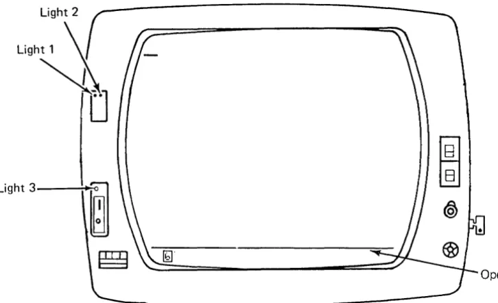
3278 Operator Panel Lights
The 3278 Operator Panel is shov/n in Figure 2-8.
Light 2
Light 1
':i
~
Light3--~
~.
Figure 2-8. 3278 Operator Panel Lights
Light 3
Ught 3, when lit, tells you that the display station is on. It will light when you turn the On/Off
q /
0)
switch to the On (m )
position.Light 1 .
Light 1, when lit, tells you that the machine hardware is ready. It will light when you turn the On/Off (
I/O)
switch to the On (m )
position.Light 2
Light 2, when lit, tells you that the display image is ready. It will light a few seconds after you turn the On/Off
q
/0)
switch to the On (fll )
position. [image:33.615.40.403.113.334.2]Operator Information Area
The Operator Information Area is the bottom line of your display screen; this area is separated from the rest of the display area by a horizontal line. The Operator Information Area is used to display operating and status messages that are associated with your display station operation. These messages are displayed as symbols, words, and numerals. For example:
)( means Do Not Enter (Input Inhibited) :,'.f".': means time is required
D represents a display or printer unit
~ signifies a malfunction, not working
- signifies a connection
Messages may be composed of groups of symbols which are read from left to right. For example:
)( ):. means Do Not Enter because time is needed for the host system to
perform a function.
)( ~ means Do Not Enter because your display station is not operating
properly (Machine Check).
C}---CJ()b means your display station is connected to printer 06.
X
~ means Do Not Enter because the printer connected to your displaystation is not working.
The operating and status messages are grouped into five categories, displayed in five different portions of the Operator Information Area as shown in Figure 2-9.
Note: For a 3278 not attached to a 3274 or to a 3276, these symbols and/or
their meanings might be different from those described here. Refer to the appropriate appendb. for a description of these differences.
Shifts and Modes
Readiness and Do Not Enter Reminders Programmed Symbols Selection Pri nter Status
System Connection (Input Inhibited) Highlighting
Figure 2·9. Operator Information Area Layout
Readiness and System Connection
The Readiness and System Connection symbols, displayed in the Operator Information Area, are used either singly or in combinations to indicate the readiness status of your display station, control unit, and host system.
BJ
and ~ (Control Unit Ready Symbols)A
BJ
or a ~ symbol appears in the Operator Information Area when the control unit that your display station is connected to is ready for operation.If your 3278 display station is in Normal mode (Normal/Text switch set to Normal) and:
• is connected to a 3274, the
BJ
symbol appears on your screen when the 3274 is ready for operation .• is connected to a 3276, the ~ symbol appears on your screen when the 3276 is ready for operation .
.8. and A (Online Symbols)
A Ready symbol must be displayed on your screen before an .8. or a J!
(Online) symbol can be displayed. The Online symbols, displayed in the Operator Information Area, are used to tell you that your display station is connected (online) to the host system.
If your display station is attached and online to the control unit; the .8. or A is displayed to tell you which oCtwo sets of rules governs your transactions with the host system. Ce~tain keyboard functions and the meanings of some 'Operator Information Area symbols differ depending upon which set of rules
, is governing. In those 'cases you will be referred to the .8. or 1. symbol , displayed in the Operator Inforination Area.
The online .8. symbol turns off when you perform any action at your display station that requires a response from the host system. When the host system responds, the.B. symbol turns on again. Whether or not this off/on action is apparent depends upon how busy the host system is and how quickly it responds .
• ,f!j
,[1J
,and TESTThe. '
00 ,
I1J
and the TEST message, displayed in the Operator Information Area, are used to tell you that:• - Your display station is connected to your job (application program).
00 -
Your display station is connected to the system operator (control program).[1J -
Your display station is connected to the host system but not to your job or system operator.Do Not Enter (Input Inhibited)
The )( (Do Not Enter) symbol tells you that your display station will not accept input from your keyboard, selector light pen, magnetic slot reader, or magnetic hand scanner. Additional symbols are always displayed to the right of the)( ,in the Operator Information Area, to define why your input devices are disabled.
There is no mechanical keyboard lock associated with preventing the use of the keyboard, such as there is on keypunch keyboards. That is, when input is dis-abled, the- keys on your keyboard are not physically locked in one position; you can still press them down normally.
Your keyboard contains a clicker that causes a click when you press the keys. You can turn the click off or on by using the Click (c:!1 ) key on your key-board (described in the keykey-board sections). When you have the clicker turned on, the absence of the click indicates that the keyboard is disabled; when you have the clicker turned off, the presence of the click indicates that the keyboard is disabled.
The reasons why Do Not Enter comes on are discussed in the descriptions that follow. Each description also tells you how to turn off the Do Not Enter mes-sage and restore your keyboard (when possible).
)( ·:·.l:·
-
TimeThis message tells you that the host system needs time to perform the function you requested. You must wait for the function to be completed.
)( '?+ -
What? (Try Again)All, or part, of the last operation you tried was not accepted by the display sta tion. Check your display screen to make sure the operation you want to perform is correct, press the RESET key to restore your keyboard, and try the operation again. If the ALT,
.u.
,or1l'
key was involved, press that key again and press the RESET key. Do not key in any more data while the )( symbol is displayed. If an IDENT key operation was in progress, it was canceled. Press RESET, and restart the IDENT key operation.)( S···(STEr··l-System Lock
This message means the host system has disabled your keyboard after processing your entry. The host system may send you a message on your display screen explaining the reason for disabling your keyboard. You may (1) wait for the host system to restore your keyboard or (2) press the RESET key to restore your keyboard.
)( .-f-+ -Go Elsewhere
This message appears if you try to take an action in the wrong location, such as:
• To enter, insert, erase, or delete a character when the cursor is in a protected field.
• To read a magnetic stripe when the cursor is in a protected field.
• To perform a cursor select operation when the cursor is not in a valid cursor select field (refer to CURSR SEL key description in the keyboard sections).
Press the RESET key to restore your keyboard; then move the cursor to another location or take a different action.
)( f
> -
Too Much DataThis message appears if you try to enter more data into a field than it can hold. Press the RESET key to restore your keyboard; then correct the en try.
)( f
f'"0~ Ur
o,ol - Numeric Data Only
This message appears if you try to enter a non-numeric character (other than 0-9, ., -, or DUP) into a numeric field. Press the RESET key to restore your keyboard; then enter numeric data. To override the numeric control, use 1}
or ~ (~ key is present on Data Entry keyboards only).
)( fU1' -
What Number?This message tells you that only certain numbers can be entered for the operation you are performing. For example, this message is displayed when you:
• Enter an invalid Printer ID or Printer Class during a print operation (refer to IDENT key description in the keyboard sections)
• Make an error when your display station is in test mode (follow test instruc-tions in the Problem Determination Guide)
)( - f -Minus Function
This message means the function (operation) that you requested is not available. Press the RESET key. Check the Operator Information Area for other symbols- to determine if the function is permanently or temporarily unavailable; for example:
o If @]..8. or [J.B. is displayed, the function (except IDENT) is permanently unavailable. Press the RESET key to restore your keyboard; then take other action.
o If @] £.
00
or [: ~00
is displayed, the CURSR SEL, ATTN, PA, andPF keys and transmission to the host system via selector pen, magnetic slot reader, and magnetic hand scanner are inappropriate at this time. Press the RESET key to restore your keyboard; then take other action.
o If @] ~ri1 or ~ ~ri1 is displayed, the CURSR SEL, ENTER, ATTN, PA, and PF keys and transmission to the host system via selector pen, magnetic slot reader, and magnetic hand scanner are inappropriate at this time. Press the RESET key to restore your keyboard; then take other action.
fa If
Ihl
~ is displayed and CURSR BLINK does not work, the D-CI ,IDENT, CURSR BLINK, and ALT CURSR keys are permanently unavail-able. Press the RESET key to restore your keyboard; then take other action.
o If TE:~:T is displayed, press the RESET key to restore your keyboard; and
follow exactly the instructions in Section 4 of the Problem Determination
Guide.
CI If 1:.
II
is displayed and none of the above symbol combinations aredis-played, the function is temporarily unavailable. Press the RESET key to restore your keyboard, check the screen, and try the function again.
o If none of the above is displayed, the IDENT function is temporarily unavail-able while
CJ-C.1n n
is displayed (printer is printing). Wait until printer finishes, or press the RESET key and take other action.)(
~n n
or)( ~n n n
-Machine CheckThis message means your display station is not working properly. The error number, nn or nnn, defines the type of Machine Check. Press the RESET key -to res-tore your keyboard, and continue. If the problem persists, refer -to your Problem Determination Guide to determine the appropriate action.
)( ~nn or )( ~nnn -Communication Check
This message means there is a problem with the communication line between the control unit and the host system. The error number, nn or nnn, defines the type of Communication Check. Press the RESET key to restore your
keyboard, and continue. If the problem persists, refer to your Problem Determination Guide to determine the appropriate action.
)( PROGnnor )( PROGnnn - Program Check
This message means the control unit detected a programming error in the data it received from the host system. The error number, nn or nnn, defines the type of Program Check. Press the RESET key to restore your keyboard, and continue. If the problem persists, refer to your Problem Determination Guide to determine the appropriate action.
)( c:J--Cl.»
Printer BusyThe )( Cl-Cl.:.; .. ::. message means the printer connected to your display station is busy and carinot perform the print operation you requested. If ~ is dis-played in the Printer Status Message Area to the right, the printer is busy per-forming your own print operation; if o-c::J is displayed in the Printer Status
Message Area, the printer is busy performing an operation for another display station or the host system.
If you initiated the print operation by using the CHl key, you can either
(1) wait for the print operation to fmish or (2) press the DEV CNCL key to cancel the operation. If you cancel the operation and o-c::J is displayed you
may be able to select another printer using the IDENT procedure and restart the print operation by using the CHl key.
If the print operation was initiated by the host system (via a P A key, the ENTER key, etc.), you can cancel the print operation by pressing the DEV CNCL key. However, if the host system initiates the same print operation again, you should either (1) wait for the print operation to finish or (2) wait for the host system to restore your keyboard.
The RESET key has no effect when this message is displayed.
)( r::::J-Cl.): .. ):. -
Printer Very BusyThis message means the same thing as the)(
CJ---CJ.: (.
(printer Busy) message, except that more time is anticipated before your print operation is accepted.)( ~ - Printer Not Working
The)( ~ message means the printer connected to your display station is not working (out of order, unplugged, out of paper, etc.) and cannot perform the print operation you requested. Therefore, your print request was canceled.
If you initiated the print operation by using the CHl key, you should press
the DEV CNCL key to restore the keyboard. Your print request was canceled. You may then select a different printer using the IDENT procedure, try to restore the failing printer, or take other action.
If ~ is displayed in the Printer Status Message Area to the right, the printer stopped working while printing your own last print operation.
)( *>< -
Operator Not AuthorizedThis message means that your display station is not authorized to do the re-quested printer-related function. Press the RESET key to restore the keyboard. Appropriate follow-on action depends upon the key you used and upon what appears in the printer assignment positions on the right side of the Operator Information Area.
1. After the Print ( D-Q ) key:
• If
CJ-CI??
is displayed, you should press RESET and then use the IDENT key to cause your new assignment to be displayed before you request a print.• If nothing is displayed and a ~ is not displayed in the Operator
Information Area, you are not authorized to print at all. Press the RESET key to restore the keyboard and take other action.
• If nothing is displayed and a ~ is displayed in the Operator Information Area, you have no automatic authorization. Press the RESET key to restore the keyboard. If a printer is available, you can establish an assignment by using the IDENT key, plus two valid numerals.
• If
CJ-CInn
is displayed, there is an error [mismatch?] in the authoriza-tion matrix (for example, the printer's buffer is too small for your display size, or Device "nn" is really a display, not a printer). Press the RESET key to restore the keyboard. Request assistance, use the IDENT function to select a different printer, or take other action.2. After the IDENT key plus two numerals:
You are not authorized for the printer you specified. Press the RESET key to restore the keyboard; then start the IDENT procedure again or take other action.
3. Immediately after the IDENT key:
You are not authorized to print at all (a ~ is not displayed in the Operator Information Area and nothing in printer assignment columns). Press the RESET key to restore the keyboard, and take other action.
)( 0-., -
Security KeyThis message means the security keylock on your display station is off. Turn the key clockwise.
)( *g'('-Questionable Card
This message appears during a magnetic slot reader or magnetic hand scanner operation if the magnetic stripe card cannot be used. Press the RESET key to restore your keyboard; then try another card or request help.
)( * ...
+':-- ,)(* ...
+':;',)( 1::.'+,?,)(* ...
+'?,)(* ..
+'?-Accent Plus What? (Canadian French Keyboard Only)
This message means you have entered an invalid accent and character combina-tion so the accent has become a stand-alone character. Press the RESET key to restore your keyboard; then re-key both the accent and the letter. See the Dead Key descriptions in the keyboard section.
Valid accent and character combinations are:
" , " ' "
aAeE uU
'eE
AaAeE;;oOliu
..
~Er
'j ~u
-.c;C
)( -:S -Minus Symbol
This message means the symbol you keyed is not recognized by the control unit. Press the RESET key to restore your keyboard.
)( CJ+-f!j
A message from the control operator (00 )
was received and rejected, Press the RESET key to restore your keyboard.)( - f *)( This message means that you tried to change the PS or highlighting selection when the host program would not allow it. The
keyboard becomes locked as a result. Pressing the RESET key will restore the keyboard.
)( ~2>:;:::'::: This message means that you tried to select a PS or highlighting when the necessary hardware was not present in the display station. Pressing the RESET key will restore the keyboard.
)( *
--4-
Operator Communication CheckReminders
This message appears when the operator presses an X.21 function key under the wrong conditions; for example, the DIAL key is pressed in the local mode.
The reminder messages are displayed in the Operator Information Area. They are reminders that a condition occurred.
~nn and ~,,-nnn Communication
This message means that the communication link that connects your control unit to the host system is producing errors. It is a reminder that you may be unable to communicate with the host system. The error number, nn or nnn, defines the type of communication problem. This message remains displayed until your control unit determines the communication link is working properly.
CJ+-f!j
Reserved for future use (appears with)(CJ+-OO
message). Ignore this symbol.X.21 Switched Network
The following messages may not appear on all 3278s.
- . : - Call Ready
This message is used when your terminal has the X.21 Switched Networks feature installed; it appears when the terminal is ready to call and to be called.
--~ Nnn or nn Call Ready with Call Progress Signal
-~.:- u? Dial In (Dialing-Originating Display)
This message appears on the display station at which the DIAL key is pressed and shows that the terminal is waiting for the dial digit number to be keyed in. On other display stations, the Dial In ( ~,,-nn ) message will appear at the same time.
-~.:- U U Dial In (Other Than Dialing Originating Display)
This message appears on display stations other than the one originating the dial-in. When this message appears, the dial digit number cannot be entered at the keyboard.
--t---'".;- Outgoing Call in Process
This message appears after (I) the DIRECT key is pressed or (2) the dial digit number is keyed in and the ENTER key is then pressed. The message means that the terminal is calling the host system.
~~ tAnn or nn Outgoing Call in Process with Call Progress Signal
This message appears when the status code (nn or Nnn) is sent back from
the network while an outgoing call is in process; for example, when the host
system is in the manual-answer mode, ~ NO! appears in the Operator
Information Area.
+--~'- Incoming Call in Process
This message appears when the terminal is being called from the host system.
---z- :,',{:' Disconnect in Process
This message appears when the terminal is in the process of disconnecting from the network after receiving the disconnect command or after the DISC key has been pressed.
-~~ c1'~1 or 5 Cj C1 Local
This message appears when the terminal is in the local mode. When the LOCAL key is pressed, the terminal cannot communicate. For the terminal to
communicate, the COMM key must be pressed.
Programmed Symbols
When one of the Programmed Symbol sets (available only when your display station has the Programmed Symbol Set feature installed) is used, the appro-priate symbol set indicator will appear in the Operator Information Area. The symbol set indicators are PSA, PSB, PSC, PSD, PSE, and PSF. When any of the above symbol sets are indicated and PS selection keys are available