ISBN: 978-1-60595-362-5
Design and Implementation of Wireless Channel Simulator
Based on Shaping Filter
Tao-Tao ZHANG, Hai-Long GE, Xue-Qian LIU, Jie LANG
Luoyang Electronic Information Equipment Simulation Test Center, China [email protected]
Keywords: Fading Channel, Simulator, Shaping Filter, FPGA.
Abstract. Currently, the reliability of wireless channel simulation is poor, and it cannot provide the interface for the actual physical equipment. Rayleigh fading channel model is used as the theoretical model in this paper, proposed a model based on shaping filter method and easy to implement for FPGA hardware. The model uses a computer to realize the shaping filter to reduce the consumption of the FPGA chip resources; linear interpolation method to achieve the Doppler frequency shift, Rayleigh fading. Test results show that the output of the hardware simulator fading characteristics consistent with the theoretical value, it can be used for wireless communication system simulation test.
Introduction
The development of mobile communication in recent years rapidly, the information transmitted in the mobile communication is achieved through the wireless channel, the performance of the wireless communication system is heavily dependent on the characteristics of the wireless channel. In order to optimize wireless communication system back-end signal processing algorithms, effectively predict, verify the performance of wireless communication systems require an accurate radio channel model [1-3]. Currently, computer-based radio channel pure software simulation technology is simple, low cost, flexibility, suitable for wireless communication theory and key technology research. However, software simulation system out of the actual situation, the simulation results are less reliable, cannot meet the needs of some system level simulation for real time. It’s difficult to provide an interface to the actual physical device, making it impossible to build a semi-physical simulation system to complete the hardware level simulation and testing. Most of the existing emulators are expensive, poor scalability, high system upgrade costs [4]. Based on the model of channel theory, this paper presents a method to realize the FPGA implementation.
Small Scale Fading Theoretical Model
The small-scale fading of wireless channel is an important feature of the wireless communication environment, including the fading caused by multipath effect and the channel time-varying. The signal received by the mobile station is composed of many reflections paths, radio waves through the various paths of different distances, therefore, the time of arrival of the reflected wave is different, and the phase is different, a plurality of signals of different phases superimposed at the receiving end, sometimes same superimposed strengthened, sometimes the reverse is superimposed weakened [5-8]. Therefore, the time variant multipath characteristics of the channel will cause the random fluctuation of the received signal amplitude.
When the signal bandwidth is less than the channel correlation bandwidth, the fading is flat fading. At this time, the multi indistinguishable paths are superimposed together, a path can be used to replace the multipath signal in the process of modeling. Set up the transmitter signal is expressed as:
0
( ) ( ) cos(2 )
t
When the delay is a particular ' , the received signal contains N multipath signals, which can be expressed as:
1
0 0
( ) N ( ) cos(2 ( ') 2 )
r i i
i
s t a A t f t f t
(2)Where fis the Doppler frequency, iis the phase of the arriving waves, aiis the signal
amplitude, they are random variables. Make:
0
2 2 '
i f t f i
(3)
Then:
1
0 0
0 0
( ) ( ) cos(2 )
( ) ( ) cos(2 ) ( ) ( ) cos(2 )
N
r i i
i
I Q
s t a A t f t
h t A t f t h t A t f t
(4) Thereby: 1 0 0( ) N cos
I i i
i
h t E a
(5)1 0
0
( ) N sin
Q i i
i
h t E a
(6)When N is large, h tI( ) and h tQ( ) are the summation of a large number of independent random
variables. According to the Central Limit Theorem, the summation for a large number of independent random variables is close to normal, thus, h tI( ) and h tQ( )is a Gaussian random
process.
In the plural form (4):
2 0
( ) ( ) ( ) ( ) j f t
r e I Q
s t R h t jh t A t e (7)
0 2
( ) j f t
A t e represents the base band signal, ej2f t0represents the carrier.Make: ( ) I( ) Q( )
h t h t jh t (8)
( )
h t represents the channel impulse response. otherwise known as fading factor. Two quadrature
components of h t( ) become zero-mean narrowband Gaussian random process. At this point, the
phase of h t( ) obeys the uniform distribution, and the envelope obeys the Rayleigh distribution:
2exp 2 22
0
r r
p r - r ,
(9)
Hardware Model
corresponding hardware structure model can be designed as shown in Figure 1.
The fading factor is generated by the Gauss white noise by forming filter, due to the high system sampling frequency, the spectrum width of shaping filter cannot be too narrow, so the maximum Doppler frequency shift of the original fading factor fm tend to be large. In order to make the
maximum Doppler frequency shift and the actual application phase matching, Linear interpolation is needed for the original fading factor. The interpolation factor M can be calculated by the following formula:
s Fading
FFT m
f N
M
N f
(10)
s
f is the system sampling frequency,NFFTis the FFT length, NFadingis shaping filter spectral
width, fmis the Doppler shift[9, 10].
Shaping filter is the core of hardware simulator, the spectrum characteristics of shaping filter determines the spectrum of the fading signal. Different channel environments are simulated by different spectral shaping filters. Since the order of the shaping filter is very high, realized by a computer forming filter can significantly reduce FPGA chip resource consumption. The linear interpolation in the FPGA can achieve real-time control of the maximum Doppler shift changes, in order to simulate the relative velocity changing.
Performance Simulation
Jakes spectrum is also known as the classical spectrum, which is commonly used in channel simulation. Its power spectral density can be expressed as:
1 2 2
2
1
( ) | | 1 / m
m m
S f f f
f f f
(11)
m
f is the maximum Doppler frequency shift, 2 is the variance. Construction shaping filter
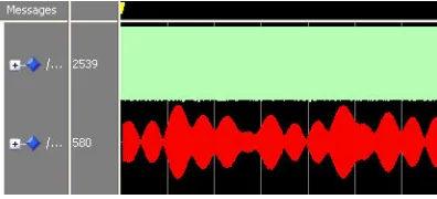
according to the formula (11), use ISE12.1 to implement VHDL code comprehensive. Through the Modelsim software to simulate the flat Rayleigh fading module, the simulation time sequence diagram is shown in Figure 2. The green wave is the intermediate frequency input signal and the red waveform is the signal of the fading process.
[image:3.612.207.405.505.595.2]
Figure 2. Simulation Time Sequence Diagram of Rayleigh Fading Module.
[image:3.612.202.412.622.728.2]
[image:4.612.223.408.129.278.2]
After the design and implementation, through the Chip Scope software to observe the waveform of the base band signal. The fading signal is shown in figure 3.
Figure 4 is a histogram of the signal amplitude fading. It can be clearly seen that the fading signal envelope obeys the Rayleigh distribution.
Figure 4. Rayleigh Fading Signal Envelope Diagram.
Using software simulation fading channel maximum Doppler frequency shift 10K Hz, the center frequency of 3M Hz. The simulation results shown in Figure 5.
[image:4.612.227.404.340.485.2]
Figure 5. Rayleigh Fading Spectrum.
In order to verify the hardware simulator, the maximum Doppler frequency shift of the measured channel is 10K Hz, the center frequency is 400M Hz, and the test results of the frequency spectrum analyzer are shown in Figure 6.
[image:4.612.216.414.572.724.2]
Figure 6. Rayleigh Fading Signal Measured Spectrum. 0 0.05 0.1 0.15 0.2 0.25 0.3 0.35 0.4 0.45 0.5 0
0.5 1 1.5 2 2.5 3 3.5 4 4.5 x 10
4
2.990 2.992 2.994 2.996 2.998 3 3.002 3.004 3.006 3.008 3.01 10
20 30 40 50 60 70 80 90 100
output of the hardware simulator is in agreement with the theoretical distribution.
Conclusion
In this paper, a theoretical model of the fading channel is studied, and a hardware implementation scheme based on the shaping filter model is proposed. The measured data show that the statistical distribution of the output of the hardware simulator is in agreement with the theoretical distribution, which can be used for the test and development of wireless communication equipment.
Reference
[l]Bello P.A. Aeronautical channel characterization [J]. IEEE Transactions on Communications, 1973, 21(5): 548-563
[2]Rice M., Davis A., DettWeiser C. Wideband channel model for aeronautical telemetry [J]. IEEE transactions on Aerospace and Electronic System 2004 40(1): 57-69.
[3]Haas E. Aeronautical Channel Modeling [J]. IEEE Transactions on Vehicular Technology, 2002, 51(2): 254-264
[4]Kai Feng Lin. Research and implementation of Semi Physical Simulation Technology for High-speed rail network [D]. Bei Jing: Beijing Jiaotong University, 2012.
[5]Rappaport T.S. Wireless Communication: Principle and Practice, Second Edition [M]. Prentice: Prentice Hall, 2002.
[6]Cost 207. Digital land mobile radio Communications [S]. COST 207, Final Report, 1989.
[7]ITU. Guidelines for evaluation of radio transmission technologies for I MT-2000 [C]. International Telecommunications Union, Tech. Report, 1997.
[8]Baum D.S., Salo J., Galdo G.D., et al. An interim channel model for beyond-3G system [C]. in Proc. EEE Vehicular Technology Conference 2005 Spring, Stockholm 2005.
[9]Min Zhang. Design and implementation of Clarke model simulation system [J]. Journal of Changsha Telecommunications and Technology Vocational College.5(4) Dec, 2006.