Systems Reference Library
File No. GENL-28 Form C24-3261-1
Report Program Generator (on Disk) Specifications
IBM 1401, 1440, and 1460
This reference publication contains specifications for IBM 1401/1460 Report Program Generator (on Disk) and IBM 1440 Report Program Generator (on Disk). The publication explains the writing of report speci-fications and the preparation of control cards, to produce object programs.
Examples and sample programs illustrate the ap-plications of the Report Program Generator
language.
For a list of related publications and abstracts, see the IBN[ bibliography for the associated ~ata
Minor Revision November, 1964
This publication, C24-3261-1, is a reprint of the pre-vious edition, C24-3261-0, including the changes made in Technical Newsletters, N24-02S1 and N24-026S.
Copies of this and other IBM publications can be obtained through IBM Branch Offices.
Address comments concerning the content of this publication to IBM Product Publications, Endicott, New York 13764.
CONTENTS
PREFACE
Machine Requirements . . . . Introduction . . . . Input Files .. . . .
WRITING REPORT SPECIFICATIONS
4 5 5 6
9 General Description . . . 9 Correlating the Report Specifications. . . 10 Printer Spacing Chart. . . 10
Input Specifications 13
Data Specifications 18
Calculation Specifications . 23
Format Specifications 30
Numeric Level Classification. . . 37
Summary 40
PROCESSING ORDER OF DISK INPUT RECORDS . 47
Processing-Order Records. . . 47
Card POR Files 47
Tape POR Files Disk POR Files
48 48 Consecuti ve Mode . . . • . . . • . . . • . 48 Random Mode . . . • . . . 48 Connol-Sequential Mode
CONTROL CARDS FOR RPG PROCESSOR . RPG Control Card . . . • . . . • . T APOUT Control Card . . . . . T APIN Control Card
MAS Control Card TRL Control Card POR Control Card RPG Translator Program
Special Feature Specifications . . . • . . . .
SAMPLE PROGRAM DOCUMENTATION
Card Input File, Monthly Expense Distribution Report Card Input File, Invoice Preparation
Tape Input File Example
Control-Sequential Disk Input File
Consecutive Disk Input File Example . . . . Random Disk Input File Example (with an IBM 1311
Sort Tag Table as a POR File) . . . .
DISK UPDATE FUNCTION FOR RANDOM DISK FILES . . . .
INDEX
54
57 57 58 58 59 60 61 62 62
63 63 74 83 90 98
103
105
PREFACE
Speed in preparing reports is achieved by rapid processing of input data and also by rapid prepara-tion of programs to produce reports. The Report Program Generator (RPG) provides easier and faster preparation of programs.
Instead of writing a particular program for a report, the user states his problem and its solution, which are the report specifications, in RPG lan-guage. RPG processes the report specifications and generates a program to write the reports. By relieving the user of most of the machine coding and program testing, RPG permits him to concen-trate his efforts on the best solution to the problem. Thus, RPG is essentially problem-oriented rather than machine-oriented.
The programs produced by RPG write reports in varying formats. Source (input) data for programs produced by RPG may be contained in card,
magnetic-tape, or disk-storage files. Output from programs produced by RPG is prepared in any combination of three forms:
• Printed report • Punched cards
• Magnetic disk records or magnetic tape records (but not both)
REPORT PROGRAM GENERATOR (ON DISK) SPECIFICATIONS IBM 1401, 1440, and 1460
MACIDNE REQUIREMENTS
Figure 1 shows the minimum machine requirements necessary to generate an RPG obj ect program. Figure 2 shows the minimum machine requirements necessary to execut~ an RPG object program. The system configuration required to execute an RPG object program depends on the object program. Each system must have a card read-punch. The minimum requirements for card, tape, and disk RPG programs are listed in Figure 2. Additional features that an RPG program can use, if they are installed on the obj ect machine, are also listed in Figure 2. The amount of core storage required to execute an RPG obj ect program depends on the complexity of the report.
INTRODUCTION
RPG produces programs that write reports of variable format from card, magnetic tape, or magnetic disk input files. Instead of writing a specific program for each report, the user 'vrites a set of specifications and the necessary control cards, which he supplies to RPG (Figure 3). At this point, the user's choice determines which form of the program is produced. He has three options for for the form of generated output:
1. the objeet program in machine language punched in cards,
2. the object program in machine language stored in
disk storage J or
System
G
StorageCo,.
I
Card Reader-PunchIBM 1401 One IBM 4K One IBM 1402 Card Read-Punch
1311
3. the report program in symbolic (Autocoder) lan-guage punched into cards.
In each of the three options, RPG produces an edit listing along with the program. The edit listing is a printed record of the source deck, as well as an analysis of the specifications and control cards. Certain kinds of errors, for example, unacceptable entries in the report specifications, will produce error messages.
If the user selects the first option, the RPG and Autocoder processors generate a machine-language obj ect program. The obj ect program is punched into cards, and an Autocoder program listing is produced.
The second option for the form of generated out-put permits load-and-go RPG operation. Under the load-and-go option, RPG prints the edit listing and generates the report program in Autocoder language. Autocoder assembles the report program, pro-ducing the obj ect program in machine language, and stores it on the system pack in an Autocoder disk area. When it completes assembly, Autocoder prints an appropriate message and halts. (The user can begin loading and executing his object pro-gram by pressing the start key. )
Under the third option, RPG produces a symbolic language (Autocoder) source deck and an edit listing. The user can modify this source deck by adding additional Autocoder instructions. The symbolic program must be further processed by Autocoder to produce the object program in machine language.
Having chosen one of the three options, the user can proceed with the next step, which is the last
I
I
-Printer Spec ial Features
One IBM 1403 High-Low-Equal Compare
or One IBM 1404
IBM 1440 One IBM 4K One IBM 1442 Card Read-Punch, One IBM 1443 None
1301 Modell or Model 2 or One IBM
or 1442 Card Reader, Model 4 and
One IBM One IBM 1444 Card Punch, Modell
1311
IBM 1460 One IBM 1301 8K One IBM 1402 Card Read-Punch One IBM 1403 None
or or
One IBM One IBM 1404
1311
Cord Reader-Punch For Disk For Printed Additional Features RPG can System (Required) Input/Output Output For Tope Input For Tope Output Required Special Feature use if they are installed on
the object machine. IBM 1401* One IBM 1402 Cord One IBM 1311 One IBM 1403 One IBM 729 Magnetic One IBM 729 Magnetic Blocked tope input records One to Four additional IBM 1311 Disk
Read-Punch {Disk output can or Tope Unit or One IBM Tope Unit or One IBM or blocked disk or tope storage drives.
use the some One IBM 1404 7330 Magnetic Tope Unit 7330 Magnetic Tope Unit output records require the Advanced Programming special feature. drive used for Advanced Programming Multiply-divide spe<:ial feature.
disk input, or special feature. Modi fy Address.
it can use an- :(: (See Note) Direct Seek special feature.
other drive.) Sense Switches.
IBM 1440* One IBM 1442 Cord One IBM 1301+ One IBM 1443 One IBM 7335 Magnetic One IBM 7335 Magnetic None One to Four additional IBM 1311 Disk Read-Punch, Madel or Tape Unit Madel 1 {For Tape Unit Madel 1 (For Storage Drives
1 or 2; or One IBM One IBM 1311 + tope input only) tope output only) 0 ..
1442 Cord Reader, One to Four additional Madules of IBM
Madel 4, and One (For both tope input and output: One IBM 7335, 1301 Disk Storage.
IBM 1444 Card Model 2.) One additional IBM 1442 Cord
Read-Punch, Modell. Punch, Modell or 2.
Indexing and Store Address Register speci a I featu re •
Multiply-divide special feature. Direct Seek special feature (IBM 1311). Selective Stocker SFoecial feature on
IBM 1442, Modell. (Th is feature is standard on model:s 2 and 4.) Modify Address.
Sense Switches.
IBM 1460* One IBM 1402 Cord One IBM 1301+ One IBM 1403 One IBM 729 Magnetic One IBM 729 Magnetic Blocked tope input or One to Four additional IBM 1311 Disk Read-Punch or or Tope Unit or One IBM Tape Unit or One IBM blocked disk or tape out- Storage Drives,
One IBM 1311+ One IBM 1404 7330 Magnetic Tape Unit 7330 Magnetic Tape Unit put records require the or
Indexing and Store Ad- One to Four additional modules of IBM dress Register special 1301 Disk Storagl'.
feature. Indexing and Store Address Register special feature.
Multiply-divide spe,cial feature. Direct Seek special feature (IBM 1311). Sense Swi tches.
* The amount of core storage depends on the complexity of the report.
+ Disk output can use the some 1311 drive or 1301 module used for disk input, or it can use another drive or module. The disk input data file can use either a 1311 drive or a 1301 module, but it must not use both. The some is true for disk output. It is permissible, for example, for the disk input data file to use a 1301 module, and a disk output to use a 1311 drive.
t The High-Low-Equal Compare Special Feature is required if (1) tape or disk input is used, (2) tape or disk output is used, (3) multiply or divide calculations are used.
Figure 2. Minimum Machine Requirements for Executing an RPG Object Program
one. He loads his object program into the system, supplies his processing-order file, if one is re-quired, and supplies his input file. See Processing Order of Disk Input Records for information about the processing-order file. The input file can be a card file, a magnetic tape file, or a disk file. The output from the obj ect program can be any combina-tion of these: a printed report, punched cards, and either disk records or tape records.
RPG Translator
IBM provides the RPG Translator program.for present users of 1401 RPG (program number 1401-RG-048) who will have IBM 1401's equipped with IBM 1311' s. The function of this prograrr. is to translate programs written for 1401 RPG to cor-responding programs acceptable to 1401-1311 RPG. A description of this translator program may be found under RPG Translator Program in this publication.
INPUT FILES
Programs generated by RPG can process input data contained in card, disk, or magnetic tape files. However, anyone program can process input from
only one source. That is, either card or disk or tape may contain the input file, but it must not be in more than one of these.
Card Files
A card file consists of all the cards in the deck. The order in which records are processed is determined by the card order. Processing the last card indi-cates the end of the file.
Disk Files
Format Specs.
--fca,d
p u n c 0 r - - -....~~
_ _ _ _ -(' \ ' ) Co Ie. Specs.
Input Specifications Sheet
~.
L:s---I
, . / - - - . r /
Object Program in Machine Language
'---r---/
IData Specs.
Input Specs.
Control Cards
IBM 1401, 1440, or 1460 Data Processing System
I I I I I I I
....
....or ... ...
....
...
IBM 1401, 1440, or 1460 Data
Processing System
~-:
L. _ _ _ _ _ _ _ _ _ _ _ _ _ _ _ _ _ _ _ I .I Ior
\
SYSTEM FileProcessing-Order File
r---,
I
~L---.n
r-:{
[)
I I
I I or
I
I---~~
I n p u t J - - - -
J
IBM 1401, 1440, or 1460 Data
Data
J
File /
/
'"
Processing System
'" '" ".
---1
i
U
r"j---I r"j---I I I I I I I
Figure 3.
.,
,,-/ ,,-/
~,,-/
Input /
D~ta
) ( Coed Output Fdeor
Printed Report
Producing Reports Using the Report Program Generator
or
or
L
RPG provides for several types of automatic header-label checking of disk files that have IBM standard header labels. Details are given in MAS Card under Control Cards.
With disk input, at least one card always follows the program deck. This card defines the processing order (or limits) of the disk data. This is true even with processing order records stored on the disk file. (The limits of the processing order records must be defined.) Processing the last such card indicates the end of the disk input file.
Organization
Programs produced by RPG can process files organ-ized as explained in Disk File Organization Routines Specifications: IBM 1401, 1440, 1460 (1311 and 1301), Form C24-3185, Systems Reference Library File No. Genl-34. Record formats applicable to the file-organization routines, described in that publi-cation, apply for applications using RPG. In gen-eral, RPG provides for processing these disk-record arrangements:.
• Fixed-length, without trailers Blocked
Unblocked
• Masters and trailers, variable length (a variable number of trailers per master)
Unblocked masters, unblocked trailers Unblocked masters. blocked trailers Blocked masters, unblocked trailers Blocked masters. blocked trailers
• Maximum record length is 1,000 characters of data. (The maxi-mum combined length of a master and its trailers is 1,000 characters.)
• For blocked records, the maximum block length Is 9,900 characters. (Master records and trailer records can each have a maximum of 9,900 characters.)
• For blocked records. the maximum blocking factor is 99 records per block. (The maximum blocking factor for trailer records is ten records per block. For master records, the maximum is 99.) Tape Files
Programs generated by RPG can process magnetic-tape input files that have these characteri.stics: • Maximum record length is 1, 000 characters of
data.
• Records are either fixed-length, unblocked; or fixed-length, blocked.
• For blocked records, the maximum blocking factor is 99 records per block.
• For blocked records, the maximum block length is 9, 999 characters.
• For blocked records, the last character in each record must be a record mark (A82).
• Padding character can be anyone of the 64 valid characters except these:
Graphics Character Name BCD Code
Jf. Asterisk B84
-b Substitute Blank A
$ Group Mark BA8421
:f Record Mark A82
V Tape Mark 8421
V Word Separator A841
GENERAL DESCRIPTION
To generate an object program~ RPG requires cer-tain information. The information answers these questions:
L What are the characteristics of the file from which the report data is obtained?
2 .. What type of information is to be extracted from the input file? From which records can these source fields be obtained?
3 .. What types of calculations are to be performed during the execution of the object program? 4 .. What is the format of the report? What headings
and constants must it contain? How should the data composing the report be edited?
As shown in Figure 3, four forms are required for writing the report specifications. The forms contain answers to the preceding questions. The information is punched into cards with one card punched for each line. These cards comprise the specifications source deck for the RPG program.
Before the actual report specifications can be written, the user must have a clear image of what he wants as the final product. If he desires a printed report, he must know the contents of each line of the report, the spacing between lines, and the posi-tioning of the information within each line of the re-port. He uses either the IBM 1403 Printer Spacing Chart, Form X24-6436, or the IBM 1443 Printer Spacing Chart, Form X24-6596, before writing specifications.
The user must also plan the format for other types of output (card? tape, or disk). Then he can make appropriate entries on the Format Specifica-tions Sheet.
Preparin.g the appropriate clhart consists of laying out the complete format of the report to ob-tain a pictorial representation of the final product. Although no cards for the source deck are punched directly from the entries on thi.s chart the pictorial representation serves as a guide to completing the four specifications sheets. It thus plays an import-ant role in writing report specifications.
The spacing chart and the four forms required are listed here in the order in which they are used. A brief des(}ription of the functions of each form is also given. Later sections will explain their use in more detail.
Printer Spa,cing Chart
The user's :Lmage of the report is proj ected on eUher the IBM 407, 408, 409, 1403, and 1404 Printer Spacing Chart, Form X24-6436; or IBM
WRITING REPORT SPECIFICATIONS
1443 Printer Spacing Chart, Form X24-6596. He must define the position of each field on each line of the report and include constant information, head-ings, and editing symbols, where applicable.
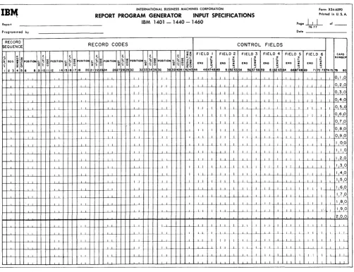
Input Specifications, Form X24-6590
A description of the data file, from which the infor-mation required for the report will be extracted, must be specified on this form. The user must describe each type of record in the data file, with its distinguishing record codes and control fields.
Data Specifications, Form X24-6591
On this form the user lists the data fields necessary for processing the report. These data fields may be output fields or factors in calculations. Each field described is associated with the input record or records that contribute to it. It is also associated with any conditions that govern the processing of those input records. Any number of fields from one or more input records can be listed as the sources of a data field. The input sources can be added and subtracted as well as moved to the data field. Furthermore, the user can state that the status (positive, negative, zero, or blank) of a data field will be needed to govern subsequent processing. For example, a line can be conditioned to print only if a particular data field is positive.
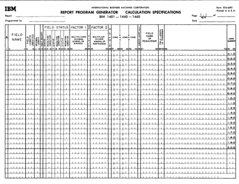
Calculation Specifications, Form X24-6592
Although a limited amount of calculation is available through entries on the data specifications sheet, the calculation specifications sheet must be used for more extensive calculations including multiplication, division, and comparing. This form accommodates calculations on data fields described on the data specifications sheet, as well as constants and the results of previous calculations. Half-adjusting and the conditions governing the performance of a cal-culation can all be shown on this sheet. Further-more, the user can define status conditions based upon the sign of the calculated result or the com-parison of two fields.
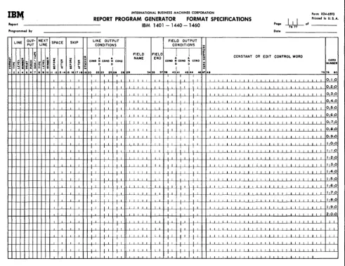
Format Specifications, Form X24-6593
conditions for output. Stacker selection of punched output or forms control of printed output can be specified. Having named a line, the user lists all the constants, data fields, and edit control words that compose the line. Control words specify where commas, decimals, and conditional credit (CR or minus symbols) are to print and where zero sup-pression is to stop. Provision is made for descrip-tion of condidescrip-tions, if any, governing the inclusion of a field within a line.
CORRELATING THE REPORT SPECIFICATIONS
When completed, the five forms are an interrelated statement of the problems specified as shown in Figure 4. Considered together, the five forms rep-resent the input file, the significant data fields within that file, the manipulations necessary to ob-tain the required output fields, and the line formats in which the fields are to appear. The spacing chart represents the output lines described in the format specifications sheet. The same line names are used on both forms.
The input specifications describe the kinds of records in the input data file according to the coding and control fields that are significant in these records. These specifications determine the con-ditions for processing data which is extracted from the input file.
The names assigned to various input records on the input specifications sheet are also used as field sources on the data specifications sheet. These field sources indicate the record from which a data field is taken during report writing.
Each input record is assigned a unique two-digit number (from 01 to 99) called a resulting condition number. As the report is processed, the resulting condition is fulfilled when a record is present in the input area which has the record codes specified for that resulting condition. The fulfillment of such a condition can govern the processing of a source field in the data specifications, performance of cal-culation specifications, or the output of a line as stated in the format specifications.
The fulfillment of a resulting condition can be compared to the transferring of a selector on an ac-counting machine during the presence of a particular card. It can also be compared to the setting of a programming switch on a stored-program machine to indicate the presence of a particular record type. This switch will be turned off when the record has been processed. The change of a control field specified for input records can also govern the processing of source fields, the performance of a calculation, the printing of lines, and the punching of cards.
The fields named on the data specifications sheet can be used as factors in calculations or as fields in lines. The fields named on the calculation spec-ifications sheet can also be placed in lines on the format specifications sheet. Sometimes the status of a field (positive, negative, zero, or blank) is important in the processing of that or other fields. It may be that calculations should not be performed on zero or blank fields, or it may be that a field should be printed in different positions depending upon whether it is positive or negative. Whenever the status of a field is important to processing, that status can be specified on the data sheet or cal-culation sheet beside the field name. Then the status is assigned a unique two-digit resulting con-dition number to represent it. Fulfillment of that condition during processing can govern further processing, as just indicated.
Thus, fields from the data and calculation sheets contribute to the lines on the format specifications sheet. A condition for a line (representing the presence of a new record in the input area, for ex-ample) can govern the printing, punching, or writing on disks or tape for that line.
This summarizes briefly the elements that enter into report specifications. In the sections that follow, each of the rules and conventions governing report specifications is presented. Sample appli-cations are used to illustrate pertinent parts of the description.
Six sample programs and their accompanying con-trol cards are shown in Sample Program Documen-tation.
PRINTER SPACING CHART
The purposes of laying out the report on the spacing chart are:
1. to establish the positions at which the various data will be printed, as well as to indicate the spacing between printed lines, and
2. to assign each line a unique identification code.
Layout of Lines and Fields
DA
CA
FO
T'D'U' &,u..,. LINE DESCRIPTION
G L U E .tLi+~eTuiii1
- · !-,-e-'-+--TI
I II"~·§ij
~f---t--,--l--e'~H+e
~~e,:,
TA SPECIFICATIONS
4.07,408,"09 f~~A~7nt II-iAi InnA ITAA 1
LCULA TlON SPECIFICATIONS
RMAT SPECIFICATIONS
,
! 1 2 3 4 5.
INTERNATIONAL BUSINESS MACHINES CORPORATION
IBM 407, 408, 409, 1403 AND 1404 PRINTER SPACING CHART Printed ;n USA
FIELD HEADINGS/WORD MARKS 6 lines Per Inch rmmgspon
_ I B M 1403, Model 1
+i
ii I I I I I I I II i III I111111
-+--IBM 407, 408, 409 I
_ I B M 14038, 1404, Model 2
T IT ITT I I 'TITi I I ' I ' I I TIl I I
I I
n i U 11 !
0 1 2 3 4 5
,
6 7 8 9 I 10 11,
12 1313 56789 12 4 789 1234 1234 678901234 6 890123456789012345 7 012345678901 2'3415i67 89 01234567 890123456781! 0123 5 78 0123 45678 012
I ! I Ix Ill( -be
-
I Ii , I I I
-
1,,1, II I I II I, I I 1 I
- - hllyll
-
I~I~ I IJ I ~: tvl _1I , II 'I 1 I j I , I I I
IBr.,
INTERNATIONAL BUSINESS MACHINES CORPORATION form X2 ... ·6S90RE130RT 13ROGRAM GENERATOR INPUT SPECIFICATIONS Printed in U.S.A.
Report IBM 1401 - 1440 - 1460
poge+.tJ-
of _ _Programmed by Date
RECORD
RECORD CODES (CONTROL FIELDS)
rx:aUENCE ,....
0
z~1~lg
z 1,,1j
1;lw"ill!
II
:~:l~
FIELD 2 FIELD 3 FIELD 4 FIELD 5 FIELD 6 H~~~~~
I~SEQ ,~ POSITION /
~ POSJTIO~ ~"'''' ~~ ~~IW POSITION
'No.t ~ ENO
l
~I~
END I ~
~ f
e
POSITlOfil~~~ POSJTJ021'~31:12 0/10 END I ~ END ~
...
J72~73
>.~ zlCU z C U Z Ci U
9 ~152~~3 54 % ~~8
. .
6 • • '0 1112 14 1!5116117 18 20 211z2 4 2E 7 • 30 323334135 36 38 3. 1 24 144 46 748 9 6Jb~63 64 6 ls7 .... S8 47,;"" 8Cl
i I I II I l' I I I 0, I 0
T I , II I I , , II i I I ~ ~ ~
0 FIELD STATUS OURCES OF FIELD
~
o J : " ,;~ ~ ~h ~~ ~ ~~
~ ~: :~~
~ I ~ I~ ~I-' ...
D~ME ~~O FIELD ~I
FiELD FIELD is F1EL :i FIELD I FIELD ~ FIEL 'i£LD FIELD
~I .. CARo
"-,,,'" CONO : CONO
~I~ ~ CONO ~ CONO -'~ ~~ ~ ~~ ~ ~8 ~ ~8 SOURCE END L£NGTH!:S
\.,-00
SOUR ~ END LENGTH::!i SOUR END LENGTH NUMBERI'---" ZI i~ Z I i!;
12 7
.
1011 1213 ,,.
17 18 19202122 242~:2Ei 28 2iI .31 ~ 32 33 3538 38 30 14243 4.ks 4849 SO .53 .... .. I •• 60 62 . . 65 6867 6970 n73 7578 00I
I I
010
I I 020
I I I " , "
I
FIELD STATUS FACljOR I ~ FAC-rER 2 A ~ T 0
U
:11 •
A.J
T
O:z:~ ~ ~5 :il~
.. ~~
~u~~A;~Nb
:~MULTLER\
l
FIELD~
NAME CARD~~.~ -'% o CONO N CONO N CON) OF -':z ... ER
AI\.!:0ME ;~
:
~H
~ ~~ ~ ~~ X DIVISOR _1\ 0 0~ REMAINDER ~~
"-U1 Z ~;
~ ~ ~ ~ ~8 ~ ~ 8 A~~:~~N~R ~~ ~~
-':::>
~ 37 3,40
t
42j43 4512 7
.
,( 1112 1314 5 I 1718192 212 3 28 2' 30 ·3~ "'~ 47 '" 53"" .5 7.i?s 8Co I 0
I I
o 2.C o 3 0
I ~
.
~I
I
' - - - LINE OUT- NEXT SPACE SKIP L~~~D~~~:~T)
I ( FI~~~D7~b:~1) PUT LINE
I~ ~D.
i
~. ~l ~D.
lclv
E 0 rl I~I ~ : NAME N CONDo ~ C( D. ~ CONDo
CONSTANT OR EOIT CONTROL WORD
CARD
:I o .. NUH8ER
~ S ~
~~ , c
!o~ 48
2 • 6 7 a 21314 IS 1617 I! 19 0 22 25~ 2' jz9 3' 5 338 4( I ~44 ~ 75 78 8C
I 010
I 020
position in an amount field where zero suppression ends is indicated by a zero rather than by an X.
Line-Identification Code
The column at the left on the spacing chart is used to assign each line a three-charaeter identification code. This code identifies the line later on the format sheet where each line is described according to type and content.
The first character of the identification code is
12l
for a heading line, D for a detail line, or T for a total line. All lines must be identified as belonging to one of these categories. Heading and detail lines can contain information from the record in the input area at the time when lines are produced; total lines cannot.Classification of Lines
Two methods of classifying lines may be used. Because it does not require a consideration of established order or rank, alphabetic level classi-fi.cation is a. quick and efficient method of assigning an identification code to each line. See Numeric Level Classification for a detailed explanation of the hierarchical relationship between line-levels. How-ever, all examples in Format Specifications and in the illustrations will be given as alphabetic
classification.
Alphabetic Level Classification.
Assign letters to heading lines, detail lines, and total lines as shown in Figure 5. The first heading line in Figure 5 is assigned HAA. The second heading line is assigned HBB; the third, HCC, etc. The first detail line is assigned DAA. The first total line is assigned T AA. The second total line is assigned TBB; the third, TCC, etc. For conven-ience, these lines are assigned pairs of letters, but
if printing occurs on a large number of lines, the lines may be classified as HAA, HAB, HAC, etc.
INPUT SPECIFICATIONS
This form (:Figure 6) specifies the input file from which the report is to be prepared. The user describes each type of input record in the file. He specifies the record codes (that is, the characters used to uniquely identify the records) and the control-data fields Significant in that record type. Records that must be processed in sequence within a control group can be given numbers representing their pllace in the sequence. The following paragraphs describe the information entered on the form.
Record Sequence
Column 1 must contain a C, D, or T for every line-entry that specifies a card, disk, or tape-record type. For a given program, all input records must be the same type.
Columns 2-3 specify two numeric or two alpha-betic sequence characters. The Report Program Generator can accommodate a maximum of 20 unique two-character sequence specifications. If, to en-sure proper processing, certain types of input data records must be in an established sequence within a control group, columns 2-3 of the input specifications sheet can contain numeric sequence entries in as-cending order.
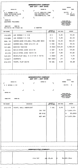
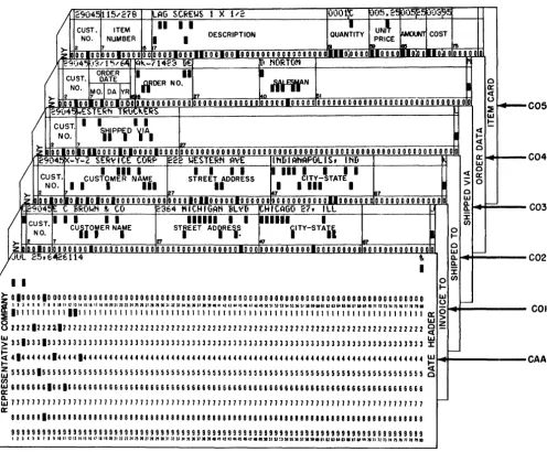
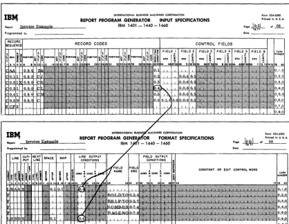
If input data records do not have an established sequence within a control group, or if it is not desirable to halt processing when the records are out of sequence, alphabetic sequence designations should be used. Some applications contain both sequential and non-sequential records. For ex-ample, the invoice form shown in Figure 7 is pre-pared from the file of cards shown in Figure 8. The source of the invoice date is a date card preceding the entire file. Because this date card has no se-quence relationship in a control group in the input file, it is given the alphabetic record sequence AA in columns 2-3 of the input specifications sheet (Figure 9).
For proper invoice preparation, the other input data cards must be arranged within customer number in the sequence shown in Figure 8. There-fore, the Invoice To header card's record-sequence number is 01, the Shipped To header card is 02, the Shipped Via is 03, the Order Data is 04, and the Item detail is 05. Each time the customer number changes, this sequence begins again.
For sequential records, Column 4 indicates the number (either a 1 or N) of that type of record in a control group in the input data file. If there is only one record of a type per group, enter a 1 in column 4. If there is more than one record of a type, enter an N in column 4.
Except for detail cards, there is only one card of each type in the control group in the invoice example. Therefore, for the Invoice To card a 1 is entered on the sheet in column 4. For the detail card an N is specified. Column 4 can be left blank for non-sequential records.
Column 5 must contain the letter X if the presence of a sequential record in the input data file is
optional. If a record type is required for proper processing, leave column 5 blank. In Figure 7, the Shipped To entry is optional because that record ap-pears only if the customer to whom the invoice is
IB~ INTERNATIONAL BUSINESS MACHINES CORPORATION Form X24-6590
Prinled in U. S. A. REPORT PROGRAM GENERATOR INPUT SPECIFICATIONS
Report IBM 1401 - 1440 - 1460
pogelLl
ofProgrammed by
RECORD
!sEQUENCE RECORD CODES
76 '77
Dol. _ _ _ _ _ _ _
CONTROL FIELDS
~ SEQ. /
z z z z z z!~ FIELD I FIELD 2 FIELD 3 FIELD!;.",4 FIELD ... ,,5 FIEI_D_6
POSITiON :; §
g
POSITION :;§ g
OSITiO~ ... § ~ POSITION'"J
~ POSITiON'"J
~ POSiTION ...§
~ ~a
~ ~ ~z --z C u z C u ~ c
e
~ c 8 ~ c 8 g c ~ $ 8 END ; END ~ END : END ~ END ~ END ~CARD NUMBEf T
I 2 3 89101112 141~161718 2021222124 267282930 3233343536 38391«:41424344 4814148 9 III~t5354 !!65711859 61162'6364 66ia76869 "172-'731747578 80
~1. ~ .... ~ .. _1.1 - . L f---L..L ..1
.1.._1.. .-f----f----LJ .. -t-- J _1.+_ I I I I I ... 1.1_ 1-- -. .. L_.L ---- L _1...1 . . L
..L . _ -_ . ...L.1 .- .... . L I I
I 1_ 1.1
--- .1 ... 1. - . -1·- J _1..1 _1
1-- ...l...L .J. - .. ---c---_...l-L._ . [ ... I 11._
--'--~---'---.J----+-I---L . ...J.I~+--l-+---"---'--+-+--+----+ .LLI
-_I I I
I
____ 1.1 . _.1. ....L..L
I I I I 11
L1 __ 1 1...1.
.J 1 .L __ 1..1
1.1.. _1.. _..L.l
...L...L Oil °
I I 0 2 0
f-J-- .L.L I I I I 1 1 I °131°
I I I I I 0 410
1_.J..._ .. 1. .1.1 ____ .L _1 1 .1 1 .QL~l~ . ..L_L_ t--.l----~-L f--L ... 1 1 _ .. 1_ 1 ~~
1--..1 ~~-r1..~-.l...~-yf---1-J----f---1-+-ll----~ I I I .1_[-L_1 ~ __ 1....1..1-.1 I '--1°1 8 1°
f-L.1- _ ._L1. f i L L _.1 J . I 11 .i .L..L 1 L L _ L 1-..1..1 __ 1..1--1 ____ ~E 1--+---'---+--+-+--L...i-+--H--+---1----4--1----H----L__'___I--+-+----f----L...L..++-++---"----y 1--+-+-+ _LL._ ~_I- ._ . ..L ____ L..l.____ _L 1.. 1 .. .1.._ ...l....L~-'--+---'----'--+...L-k L I I 0
°
1--+...L..+--+-+--L..l.-I--+--t_+_...L..J4-+--+---I-....L--'---I----+--+---j1----l--...l....+~-+-~ ..L..l--+---+----.J----+----L--'--f--+-+--+...J.~...L....J II,--+...L....f--L..l._ .1... _L.l.._+---'--+---'I ____ -'--+ 1---'1~--'---'4--'---1____l_...J.-.J--Lt--L~~I I .-l---If--I---+--'-.-l-L..l.- .1.. _ L L f----L.- I 2 0
I J L _.1....l. _1. 1.1 1 1_ I.. l1.. . ...L. --'--. ..L _ L . 1 ~()
I ... L_L . 1 . 1 LI---'-I----IL.+...L..f----L . ...L..p-l--.L.lII.-I--..L..I--1 .. L1. I I 4 0
f-+--'----H-I----L..l.-+-H--f-...L..J4+-H....J...L..f4-Hf---1--'---l---+-+-t 1 1 ... _ _ 1.1 I .. ..l. ____ l_L . 1_ .L1.. L_ 1...11 I 1151
°
I--+...J.f--H--f---J'---'--+-+----+--f---J~+-II_+-+----L..L+----I-+-+--L...L.+ .. ,.+.+-"'--'--I---.J----+____I__.L....ll-+-+---Je--+--'---lf--.'----'-I--+-.L...+---.L.L+_L _LL J. - L.1 _.1.. . ..L1... 1 L 1 L...L. ~1()
_++----f--L-+----L..l.--+---'---I---1....J...I----l--_I----.L..J.-+---'---I----'--...L....j~L J._1. 1...L..L . L _-'---I.l!.l~
-f---JLL--I----+-+--+---'---ILL--1----f----L_~-.L..J.-+-. .l----~----L-+~-I-i----L+--'--I----l-~I----l-~L----~I.____I__L4----'L8~0~
f---t-...L..t-+-+----..L...L_+_+---I-_+_...L..JI_+-+--1-+...L..4-++-+...L--1----~--+-+-+.-. .J...--'---I--++---II--...L--'----H-+- ____ 1. .. L 1
1--+---'---+--+-+-..L...L-t-+--+--t...L...J4+-1-+ .l....L--I--+--+____I__..L..l--+-+-+---+-L -L+ 1.1 L
f-+--'----~-~L..l.--f-H~...L..J4+-H....J...1..f-- -~-"I----l----'----+--+_+_+~...L4____~+_+_~.L+~ L1 1 -1 .. -'--+---'--1---'----1.. f--L f---L .. 1 _1.. 1 J _ L I I J.I_
1--+---'---+--+-+-..L...L_+_H_+_...L...J4-+ I----~ - -I--~ -.1- 1 I I . L . .L __ .. .1 .. _+----L....L-I---L+~L...l__...L..jc_-LL ...L.I-.J... ._1....1.. +---'---'---I---I--+-I---L+--'----Lf--I-...l.. .1 1 ..L I .1._ L _ 1 . .L I 1.1----_1.
~..L..~-.. 1-. ..L.L-+ __ .J----+--+--~-I----+.I____ ...L...L_I--r-.I--. ..l--+---'--L+---'---.l....1----L+--' ____ ~-LL-...L.t--.1....1 L~..L.L .. t . L.i I L _l._L
Figure 6. Input Specifications Sheet
sent has instructed the Representative Company to direct shipment to an address different from his own. An X in column 5 specifies that the Shipped To record is optional (Figure 9).
Any input disk or magnetic-tape record that is designated as optional cannot exceed 200 characters.
Record Codes
An input record can be identified by any number of record codes. All record codes specified for a single record type are considered in an AND rela-tion. That is, all the codes must be present in the record. Columns 6-41 of the input specifications sheet provide space on one line-entry to specify as many as six record codes per type of input record. It is possible, however, to specify more than six record codes per type by using more than one line-entry.
• The first line has no resulting-condition number in columns 42-43. Columns 1-41 are filled in as normal.
.1 I I I 1 I I I
• Columns 2-5 are filled in only for the first line.
• Succeeding lines have a C. D, or T in column 1 and the additional record codes.
• Only the last line-entry for a single record type has a resulting-condition number in columns 42-43.
Each input record is analyzed to determine if it meets the record code specifications of the first record type on the Input Specifications sheet. If the input record does not meet the first record code, the program will determine if the second record type conditions are satisfied. When an input record satisfies the record code specifications, the asso-ciated input resulting condition is set. Only one input resulting condition can be set for anyone in-put record.
[image:14.613.57.559.64.450.2]INYOI'CE TO
r --,
E C BROWN & CO 2364 MICHIGAN BLVD CHICAGO 27, ILL
L -l
SHIPPED VIA
WESTERN TRUCKERS
ORDER DATE
03/15/~4 AK-71423 DE
ITEM NUMBER
115/278 LAG SCREWS 1 X
REPRESENTATIVE COMPANY ANY CITY - ANY STATE
DESCRIPTION
1/2
SHIPPED TO
r --,
X··Y-Z SERVICE CORP 222 WESTERN AVE INDIANAPOLIS, IND
L -l
D NORTON
QUANTITY &
UNIT OF MEAS.
2 C
115/282 I.AG SCREWS 3 X 1/2 5 C
SBN- 02
369-2HF
101-224
21-564
21-572
143-210
7430217
216-210
r
HAMMER-ADZE EYE,BELL POLL,RND NECK 12 DOZ
HAMMER-BALL PEEN 210,3/4 LB 4 DOZ
HASHING MACHINE 8 EACH
NAILS-STEEL WIRE 60-2 IN 6 CWT
NAILS-STEEL WIRE 100-3 IN 4 CWT
I3RUSH,FLAT WALL 3 X 2 5/8 X 13/16 6 EACH
GROMMETS 720 EACH
PAINT, FLAT WHITE 12 GAL
REPRESENTATIVE COMPANY ANY CITY - ANY STATE
r
E C BROWN f~ CO
L
SHIPPED VIA
ORDER DATE
ITEM NUMBER DESCRIPTION
216-418 PAINT, WALL UNDERCOAT
L
INV TOT
2:r: DISC
NET AMT
QUANTITY &
UNIT OF MEAS.
1 GAL
NUMBER
26115 1 JUL 25,64
29045
PLEASE REFER TO OUR INVOICE NUMBER
WHEN REMITTING
TERMS 2% TEN DAYS
F. O. B. FACTORY
UNIT PRICE AMOUNT
5.25 10.50
5.30 26.50
10.50 126.00
12.64 50.56
165.00 1,320.00
8.30 49.80
7.80 31.20
.95 5.70
.01 7.20
2.85 34.20
26115
PLEASE REFER TO
OUR INVOICE NUMBER WHEN REMITTING TERMS 2% TEN DAYS
F. O. B. FACTORY
UNIT PRICE
2.95 2.95
$ 1,664.61*
33.29CR
$ 1,631.32*
r---~---~---~---L---~
f-- - - -- - - --~ - - - . - - - ----~
PI:PIPII:CF,ITATI\'E COlepe""
[ _______
---L---'~-T-0-T---J~LL--2-5-,6-4----L·---7-4-,L9_:2_1_.-3_5*_*
____~
Figure 7. Invoice Example
[image:15.613.59.368.47.706.2]/ 2904~ 115/278 II-AG StREwS 1 X 1 .... 2 0OO1:t u05.2~ rJij~~ p03~~
CUST. ITEM
II
I I IUN~
~
DESCRIPT ION QUANTITY COST
NO. NUMBER I I PRICE
>- 2 It 5 7 lei Is 1M 17&
~ 0010010_0 OlD 0 0 0 0 0 0 0 0 0 10 0 0 110 0 0 10 0 100000000000000001111100000111000.0.10:0 0110;0 010 0' 10
~9(14"5 )3.'1 '; .... f,4i "--71 423 DE 1[1 NORTON
ORDER
I
II
~CUST. DATE
ffDER NO. IYfif'N 0
NO. ~O·I
DA IVR 0::
2 .. 127 LIo DI . «
~ 100 100 1010010t o 0 • 0 0 0 0 0 0 0 0 010 0 0 0 0 0 0 0 0 0 0 0 D 0 0 0 0 0 10 0 0 0 0 0 0 0 0 0 0 0 0 0 0 0 0 0 0 0 0 0-00 0 0 0 0 0 0 0 0 0 0 u
:E
r---/
29i)4~ ~ES.1ERtl lRli .... "-ERS lLJCUST. I I I I
t:
\1pP\O
~IAI «NO.
....
«
2 7 ~ 0
>z 10 0 0 I 0 Olio DO 0 0 O~OIO 0 0 0 10 0 0 0 0 0 00 0 0 0 00 0 00000000000000000000 0 0 0 00 000000000000000000 a::
~904~~-Y-Z S.ER~ICE CORP ~22 wES1ERN AVE INDIANAPOLIS, IND I.LJ
/
IIII I
I I I II III I
I
I I
« 0CUST. 0::
CUSTOMER NAME STREET ADDRESS CITY-STATE
> 0
NO. ~I I
I
III
II
471
I III
I2 127 87 0
>;
DO 00 liD 10 10 10 0 10 0 0 0 0 0 0 0 0 0 000010"000001000000 oooooooooooUOOOOOOO 000000000,00000 UJIl. ~
_~9;')4:5 IE. CBROwN ~ CO 2364 "'CH'GAN BL~D ~H I CAGe. 27, ILL Il.
/
CUST. I I I I I111111 I I .11111
I
I f/)CUfiOrER NAIME STiEET ADiRE \ : iITY-STA.i 0
NO.
....
)0- 2 7 27
'"
R70
z 100100 100000001000000000000 00000000000000001000 o 0 0 0 0 0 0 0 0 O~O 0 'o--'-LO 0 0 0 0000000000000 I.LJ
I--II.JUL 25,6~6114
"
a.. -Q.I :i:
C05
C04
C03
C02
I I o f / )
....
>-01000010000000000000000000000000000000000000000000000000000000000000000000000000 I.LJU
I--!
I I 3 4 ! , I • I II II 1113 14 II II 1111 "10 21 n 23 24 2! 2f 21 2I2IlO 313133)4 3! Jl31. 3140 41 4/U 44 4~'" 4141., 1O!1 !I !HOBI!I ~ H IU' II 'HUHI""" II II 12 13 l4 n" II " " .-:E 111111111111111 I 11 I 11111111111111111111 111 I I 11 I I 11111111 I 1 I 111 I I III 1111 I 11111111
ffi
0 >822221222112222222222222222222222222222222222222222222222222222222222222222222222 ~ ~
COl
~ 33133313333333333333333333333333333333333333333333333333333333333333333333333333 ~
S
41444444144441444444444444444444444444444444444444444444444444444444444444444444~
-
-~ 55555155555555555555555555555555555555555555555555555555555555555555555555555555
g
CAA
f/)
~ 18166661661666666666666666666666666666666666666666666666666666666666566666666666
~ 711 71111111111111111111111 7 111111111111111111111117 11111111111111111111111111111 t--0::
88888818888888888888888888888888888888888888888881881181888818888888188888888888 999999999999999999999999999999999999999999999999999999999~9999999999999999999999
1 1 1 4 ! ' "'~IIIII3~IIIIIIII~~lInn24nKn2lnlO~nU)4H.U • • • ~UU44Q.41.~~~~~~D~~~".~IIUM~."ua~lI»nl4n"II"n~
Figure 8. Input Data Cards for Invoice Preparation
[image:16.617.52.548.66.475.2]the record code fields. (Columns 6-41 w:ill be left blank.) When certain input records are present which are to be merely read and bypassed, the records to be processed are listed first with their identifying record codes.
Figure 9. Excerpt from Input Specifications for Invoice Report
When all input records are to be processed alike without regard for their record codes, a single record type may be specified without any entry in
16 RPG (on Disk) Specs., 1401, 1440, and 1460
The last record type entered on the Input Specifi-cations sheet can be left blank in columns 6-41. Any record not satisfying the preceding specifications will satisfy this condition. No processing need be performed for this particular type of record.
Columns 6-8 state the position number (input card column, disk-record position, or tape-record posi-tion) that contains the record-code charaeter.
negation means that the code described is not pres-ent in the record specified.
Column 10 must have a Z, D, or C, depending upon whethe]; the record-code comparison to be made is that of the zone portion only, the digit portion only, or the full character.
Column 11 is used for the particular record code. Any valid alphameric character (including a blank) can be entered in column 11. If the entry in column 10 is a C, the character is entered in column 11.
If the entry i.n column 10 is a D, the exact digit is entered in column 11. If the entry in column 10 is a Z, any character containing the desired zone can be entered.
Columns 12-41 are used for five additional record code designations in the same manner as 6-·11.
All record-code entries describing one input-record type are represented by one resulting-condition entry entered in Columns 42-43. The resulting condition is a unique two-digit number arbitrarily chosen by the user to represent a record (in the area 01-99) coded according to his
specifications.
It may be useful, however, to assign the same resulting-condition number to more than one record type.
Figure 9 shows the entries necessary in columns 1--43 of the input specifications sheet for the Invoice Report.
In some applications there is more than one kind of record of a given type. For instance, in the invoice example just given, suppose that the file of input data cards contained three kinds of detail cards:
1. a I-punch in column 80, 2. a 2-punch in column 80, 3. a 3-punch in column 80.
For other reports, the 1-, 2-, and 3-punches might be significant, but in preparing invoices all three kinds of detail cards should be treated as one type. Therefore, they would receive the same se-quence designation. Furthermore, suppose that in the input data file it were possible that for a given customer there may be any number of detail cards of each kind, including none of some kinds. Each kind would have N-number within a control group, and each kind would be optional within that group. The specifications for the conditions just stated consist of a separate line-ent.ry for each kind of detail card, each having its own resulting condition (lines 2, 3, and 4 pf Figure 10).
When records that. are coded differently are to be processed alike for the most pa.rt, they may have
Figure 10. Three Kinds of Input Records Defined as One Record-Sequence Type
the same sequence designation in columns 2-3 (whether that designation is numeric or alphabetic). To represent their unique record codes, however, and to distinguish them later, they normally receive different resulting-condition numbers. Such records are said to be in an Or relation.
Control Fields
Control fields are record positions containing infor-mation identifying the classifications to which the record belongs. Columns 44-73 of the input specifi-cations sheet list the control fields present in each type of input data record. Each field is described by its right-most position in the input record and its length. The fields are specified in ascending sequence of control levels beginning with the entries for the most minor level in Field 1 (columns 44-48) and continuing to the right as far as necessary. Six is' the maximum number of control fields that can be specified.
Frequently, it is necessary to process data having split control fields. For example, assume that the intermediate control field is split into two different parts of the input data record. To handle this condition properly, one portion of the field should be specified in normal fashion as Field 2 and the other portion as Field 3. Calculations, output, etc., conditioned by a break in Field 2 will be per-formed whenever either Field 2 or Field 3 changes. Minor control is still affected using Field 1,
whereas major control will utilize Field 4.
Figure 11. Input Specifications for Invoice Report
If there are more than six record codes in a record type, the control-field entries are made only on the last line-entry for that record type.
Sequence Control
A special entry applies when the records of an input file are required to be in a fixed sequence within a control group. This is the SCFx entry in columns 1-4, which is used for numerically designated types of records. The x is the number of the control field. A change in this control field means that the se-quence is to begin again. In the invoice example the sequence of records specified relates to customer number. Every change in customer number means that the sequence of records begins again with an Invoice To record. Because customer number is field 2 (Figure 11), the proper entry for this Invoice Report is SCF2 in Columns 1-4 on the line below the last sequential record specification. Every applica-tion that has sequential-record specificaapplica-tions must have an SCFx entry at the end of the input
specifica tions.
A break in the control field which is specified in the SCF entry means that the sequence of input is to begin again starting with COL Therefore, COl should never be designated as an optional entry.
There are three causes for an out-of-sequence condition:
1. A control break occurred on a type of input other than a COL
2. A required numeric type of input in a control group was missing.
3. A non-optional card was missing. However, if a COl type of input is designated
N
(one or more of this type is allowed), then a control break will take precedence over a missing non-optional card.Page Number
Columns 76-77 are used for page numbering. The page-number entry is in the upper right-hand corner of the input specifications sheet. The pages are
numbered consecutively beginning with the spacing chart as page 01.
Card Number
A three-character card number in Columns 78-80 establishes the order of entries on the specifications sheet. The first 20 lines of the sheet are prenum-bered 010-200. The six unnumprenum-bered lines at the bottom of the sheet are for the entry of statements inadvertently omitted and for sheet extension. In-sertions can be referenced by numbering the ment with the hundreds and tens digits of the state-ment it is to follow and with anyone of the units digits 1-9. This allows up to nine insertions between two consecutive prenumbered statements.
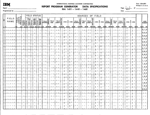
DATA SPECIFICATIONS
The Data Specifications sheet (Figure 12) describes the fields that appear in the output and those used in processing.
D (Data)
Column 1 must contain a D for every line-entry on the sheet. The D identifies each entry as a data specification.
Field Name
Columns 2-7 must contain a name for each of the data fields necessary to process the report. Numbers and special characters should not be used in a field name to avoid conflict with field names and instruc-tion labels used by the RPG processor. Any name must be left-justified. The alphabetic field name CONTD must not be used on the data speeifications sheet. To use the field name PAGENO, see Serial, Record, and Page Numbers under Data
Specifications.
-Note: Any number of line-entries for the same data field (same Field Name) is permitted. In these cases, write the line-entries in the order in which the data manipulations should occur.
Field Length Unedited
IBr.,
INTERNATIONAL BUSINESS MACHINES CORPORATION Form X24·6591 Printed in U. S. A.Report REPORT PROGRAM GENERATOR DATA SPECIFICATIONS Page
hL
of _ _ _ _IBM 1401 -1440 -1460 7677
Programmed by [late _ _ _ _ _ _ _ _
FIELD STATUS SOURCES OF FIELD
FIELD oJ: - I I - ~~ <oz z z z
~ ~~ u 0
D w I ! ) ..J zo 0: 0 A
FIELO ~
0
A 0
,..- 5E FIELD FIELD ~ ~
i
ANAME _z
..
~i
FIELD "' CONO ~ COHO FIELD FIELD CONO ~ COHO FIELD FIELD FIELD COHO ~ COHO CARDLJ..W '"
~~ I- ",0 SOURCE
i
END LENGTH ffi SOURCE ~ END LENGTH ~ SOURCE END LENGTH NUMBER -I~ ~ ~~ ~
I 2 ., 8 10 II III 19 7 18 19 20 21 22 242826 2829 31 3233 3& 38 3839 414243 4&4e 4849 eo 52&3 &e ee 58 &9 80 6263 65 6867 6970 7273 7578 80
-f.--L-L..L.l...L I _LL I ~
I
L - -~ +~
_~L.L.LL ---Ll_ I I I I 1 I 1
-f-LL.L.LL ---Ll_ I I I I I I + 1 1 I
I I I I 1 L I 1
_~L.L.LL I I I 1 ...L- I 1 LI 1 I 1 I
_.--L~ I I --1.,.. I I 1 I L I I I 1 I
I
_ .--L .. L_.LLL I I 1 1 1 I I I I I L . .L r----f·.L 1 _ .--L_L .. LLL _1.._L . .L I 1 -~ I _ L __ _1.1 f---LL -+ 1 t 1 _ .--L.L .. L_LL 1 , . L L .. L~ ..f 1. +..L.. _.--L.l....L...L..L 1 1 _L ..L f---..L.. LL __ L_L 1---11.-I - - l l
-+...L
_.--L~_ LL 1 I I L _.L I 1 LL_ I-_+L I I I L i I I 1 I .1....-L _ L I I I I
1. I ...L... I I l..L..
_...l...l....LLi I 1 1. l_L _ _ L1.... _1. I 1 -'--_ _...l...L.L..L.L .--L.l. -..Lj __ L __ 1. ...L... ---L.L ---I _1 L _ L L 1 1 I _ -1..L.L..L.L ---'---.l. I I ,..L_ 1._ Ll _1. I
_-1J....i....Ll. I I I I _..L L...L I--+_L
-+
_ _ .L_L1 L1. _.1 _L j ___ .L ---_.--- .JL __ .l L i I 1L_---'--__ L - ----'---'- 1. 1 I
T
1.
1 I 1. I I
I
r-~---'_LL.1 I .L --'--- - ---' I I _LL 1.1 I 1 -I L
t--~----'--L..l I I 1 ---'- LL f----I----L..L c-L .1---f---- +J +..L
L 1 . ..L 1- ___ L..L_1.
I_~-I-~I I I 1 I L 1--_1. f--~....L.. 1--. ___ L -'--_ I I 1 I I 1 I J ~ J
I I I I I 1 1 I
Figure 12. Data Specifications Sheet
report were Jul. 25~ 64, with the period and eomma supplied by program editing, then the entry for unedited field length would be 007.
Note: The maximum unedited field length is 099.
!)ecimal Length
]8'or numeric data fields enter in Columns 11-12 the number of positions of the data field that is a decimal fraction. (The maximum permitted is 09.) For example, suppose that a data field were of the form xxx. :xx. The unedited length would be 5 posi-tions. Of these 5 positions, 2 positions would belong to the right of the decimal point. Hence the entry in columns 11--12 for this data field would be 02.
Note: For a numeric data field that contains no decimals, enter 00. For alphabetic or alphameric data fields, leave these columns blank.
I I
--.1 J ____ _I
_+--1-
:
_1..L_ ~LJIr-+L
/-1 1 1 °11_LO--1_ .. __ J~ W-l- ~-~LL I-_+-1-
_+-1
1--1 ... 1_ 012 10..--1 __ I I I I 1 -' I I 1--1_ ~LL
_+1
f 1 __ -1-L .<J.L~~
--1 1 I 1 1 1 I 1 L 1 1 0 4 0
I I I I I_L t-I--I J i L 1 1 I 1 050
I I I I I .. t-J I 1 1 1 L 06 0 I.J I I I I 1 I +_ J 1 --' __
I _LL I---LI 1 L _ L L 0.1~
L.1_ _LI I--L-L
I 1 - -t---'- +...i. ..l.._.L_ ()LEl.t9
....L..l. L_L ---Ll_
--·-I+..L
+_L 1 L __ +1- t1 1.1_
°191°
....L_L I
l...L ---1----'-- LL __ ...l..I_ f--LL 1.. L_L 1 1
°
1°
I I I 1 I L i J 1 1....L_I _LL ~LJ I I 1 _L1.... '.JLL O
I 1 I I 1 i J I 1--'---1 1 I L ___ + 1
t----'- _LL 11 2jO
....L_L 1 I 1 I 1 I _ ....LL. _LL 1 I I I 30 ....L_L _ __ L..-L ....-L.L 1 J....L.. ___ 1.L_ c-LL 1 --'- _I L 1141
°
1 1
I .L.L
-+---'-
+-'-- LL--j --.l..L.. :_-'--L ---I---+--y -f...i ---'--L.., ~10I L __ 1..1.. _LL -t-L +---1-J..LJ __ .L.1_ -1_1._ __ +1._ + 1 . _Ll_ 1~10 1 1 1...l. _ _ L_L ---'_ L_
__ +L
/ I LL 11710 L ~_L --\--L l~ f-LJ- -1_L
-+--'-
t-1- L.I_ -'--'-~L LL.. ----'--L. I I t I I 1 --'---'--...l._1 1 I~
I L _I
I I.L 1
200
1
____ +1
_~ _1 --l--L --'--_1 lL-Le- 1...L I I I - t-1 t 1 I 1 I I j I ~_L I I 1 I I 1 ~lf-..J.-L 1 I I
I L 1.1. J_L_ f--ll 1 I I l LL. _1 I
1
L_ +_L L _1 Lf--- IL I 1 _L-'----
t----l---'--1 I I I I 1 l J I 1 1 I 1 I
I I I J J I 1.1
1 1 I 1 1 11 1 I I
I
I ISources of Field
Columns 22-72 specify three sources of the report field. If more than three sources must be specified for a report field, use more than one line. Refer to the Disk Update Function for Random Disk Files section for special use of these columns for the update function.
Columns 22-24 define the first source of the field. Possible sources are input records, serial numbers, page number, and record-count numbers. The entries are Cxx, Dxx, and Txx for input record sources, SER for serial numbers, PAG for page number, and RCT for record-count numbers. When the field source is an input record, the appropriate entry must come from columns 1-3 of the input specifications sheet.
[image:19.617.65.564.67.450.2]the units in the field for which an N is specified. If the units position contains no zone, this specification will create a 12-zone in that position.
The other entry permitted in column 25 is an M. This identifies the entry as a month-field conversion specification. (See Month-Field Conversion under Data Specifications for an explanation and example of this entry.) Otherwise leave this column blank.
Columns 26-28 contain the location of the low-order position of the field in the source record. For fields whose sources are SER, PAG, and RCT, these columns should be left blank.
Note: For IBM 1401 and 1460 Data Processing Systems using 51-column input data cards, see Special Feature Specifications.
Columns 29-31 must contain the field length in the source record only if that length is different from the unedited (report) field length specified in columns 8-10. For example, in Figure 13 the entry on the data specifications sheet for SOLDTO gives the unedited field length in columns 8-10 as 020. Because the source field length is the same, columns 29-31 are left blank for that field. The entry for AMOUNT specifies an unedited field length of 006 in columns 8-10. This provides sufficient positions for the largest total expected although the source field length specified in columns 29-31 is 005. The source field length should be left blank when the source is SER, PAG, or RCT.
Figure 13. Data Specifications for Field Sources
One of the following seven operation characters must be specified in column 32:
Blank Move the source field to the data field. A Add the source field to the data field. S Subtract the source field from the data field. +
o Reset the data field to zero before adding the source field +
to it. (Punch 12,0 for 0.)
o Reset the data field to zero before subtracting the source
field from it. (Punch 11,0 for 0.)
D Move the numeric portion of the single-character source field to the units position of the data field. The zone portions are undisturbed in both fields.
Y Move the zone portion of the single-character source field to the units position of the data field. The numeric portions are undisturbed in both fields.
20 RPG (on Disk) Specs., 1401, 1440, and 1460
Figure 14 illustrates the use of the single-char-acter move-numeric and move-zone operations.
Figure 14. Single-Character Move-Numeric and Move -Zone Operations
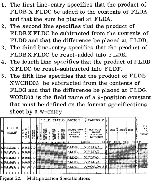
Each line-entry is explained as follows: 1. The first line-entry specifies that the
six-character field at position 074 in input record C06 should be moved to the data field, AMOUNT. Furthermore, the zone portion of the single-character source field in column 69 of the same record is to be moved to the units position of the data field, AMOUNT. By using an entry such as this, the high-order position of the source field can contribute the sign to the units position of the data field.
2. The second line specifies that the five-column source field in columns 49-53 of record type CBB is to be moved to the five-position data field, FLDR. The zone portion of the single-character source field in column 70 of CBB is to be moved into the units position of the data field,
FLDR. By using an entry such as this, a data field can acquire its unit-position sign from any position in a record. By choosing a one-position field source containing no zones for the Y oper-ation, an unwanted sign in the units position of the data field can be removed.
3. The third line specifies that the numeric portion of the one-column source field in column 35 of card type C02 :is to be moved into the one-position data field, FLDS. By using an entry such as this, a single-column source field that contains an unwanted sign can be moved into thIS data field without the unwanted sign.
Because the Y and D operations are single-character move operations, it is not necessary to specify the field length in Columns 8-10. When Y or D operations are specified on the same lines as another operation, they should follow the other ation. This ensures the proper sequence of oper-ation in the object program. For example, in the first two line-entries in Figure 14, the Y.-entries are made to the right of the blank (move) operation entries.
For exarnple, if a. field being described is the result of adding or subtracting more than one field from the same source record, and if that field must be reset prllor to the first operation, then the source fileld described first (in columns 22-38) should be the one that is reset-added or reset-subtracted.
Columns 33-35 can be used to specify a condition that is to govern the operation upon the source field. It can be either a positive condition, such as F3 to indicate a change in control field 3, or a negative condition, such as NF3 to indicate no change in con-trol field 3. The conditions specified on this sheet are the resulting conditions of the input specifications sheet, control-field changes (F'1-F6), sense switch settings (SB, SC, and SD), resulting conditions specified by other entries on the data sheet, or the negation of any of these when preceded by an N. The following list shows the resulting conditions which are defined by the RPG processor.
FI-F6 OF IP SB SC SD LC
Change in control field 1 through control field 6 (columns 44-73 of Input Specifications Sheet) Page Overflow
First Page Sense Switch B Sense Switch C Sense Switch D
Last card, tape, or disk record
In the Invoic e Report shown in Figure 7, the minor group-indicative information (Item Number, Description, Unit of Measure, and Unit Price) is to be obtained from the first card of each minor control group. Hence the specification for ITEMNO is con-dition F'1 in columns 34-35 of the data specifications sheet (Figure 15). This entry specifies that the source field is to be moved to ITEMNO only from the first card after a change in control field 1.
Other permissible entries in Columns 22-72 are RCT, SER, and PAG. See Serial Record and Page Numbers.
Columns 36-38 can be used to specify a second condition governing the operation upon the source field. If two conditions are specified, they are con-sidered in an AND relation. That is, both conditions specified must be met before the operation specified ill Column 32 is performed upon the source field.
When the field being specified has more than one source, the second source is specified by entries in Columns 39,-55 in the same malnner as the first
Figure 16. Specifying Four Field Sources
Figure 1S. Conditioning Operations 011 Source Fields
source in Columns 22-38. The third is specified in Columns 56-72. If more than three sources exist for a field, more than one line-entry is required to specify the sources. In such instances, the first line-entry for the field is prepared as previously described. The second and succeeding-line entries for the field have a D entered in column 1. Columns 2-21 are blank. Columns 22-72 are used, as re-quired, to enter the information for the remaining sources of the field. Figure 16 is an example.
Field Status
The user can govern subsequent processing accord-ing to the status (positive, negative, zero, or blank) of a particular field. Columns 13-21 of the data sheet are used to assign resulting-condition numbers to represent one, two, or three possibilities for the status of the field. If the field's status is not sig-nificant in the control of processing, leave columns 13-21 blank.
Column 13 is used for the first status character. The acceptable characters and their meanings are:
B Blank
Z ± Zero (signed or unsigned) or blank N Negative, including minus zero P Positive, including plus zero
Note: Minus zero can occur during processing on the IBM 1401. 1440, or 1460 Data Processing System.
The field status refers to the condition of the data field after the operation has been accomplished by the object program. For example, if a source field is added into a data field with a zero status defined as Z25 in columns 13-15, condition 25 will be ful-filled by the program whenever the specified ad-dition results in a zero data field. This conad-dition can then be used to govern other operations in the program such as the performance of a calculation.
Refer to the first line of Figure 15. The source field ITEMNO from C05 will never be blank. It will be blank in the data field ITEMNO only before print-ing the first set of total lines. (This condition takes place before the input file information has been transferred to the fields in the data specifications. ) By setting the resulting condition 07 when ITEMNO is blank, total printing can be suppressed. See Suppression of Output from Run-In Control Breaks under Format Specifications.
Each resulting condition specified under Field Status must be different than any other resulting condition specified here or elsewhere. Any attempt to set the same resulting condition under either of several different conditions will usually yield incon-sistent results. For example, a resulting condition can be set as a result of one specification, and yet it can be turned off by a subsequent specification.
Columns 16-21, if necessary, specify two more sets of status conditions for the data field.
Page Number
Columns 76-77 are used for page numbering. The entry is made in the upper right-hand corner of the data sheet. The pages are numbered consecutively beginning with the spacing chart as page number 01.
Card Number
Although the entries on the data specifications sheet can be in any order, a card number (Columns 78-80) aids identification of line entries.
Conversion of Month Field
In many applications a month field is a single char-acter with the months January through September represented by the numbers 1 through 9, and the months October through December each represented by a zone or a combination of a zone and a number. In these applications the single-character repre-sentation of the months can he converted automat-ically at obj ect-program time to the corresponding two-character representation. January through September are then 01 through 09; the months
22 RPG (on Disk) Specs., 1401, 1440, and 1460
October, November, and December are 10, 11, and 12.
Figure 17 shows the specification for month-field conversion used in the Monthly Expense Distribution Report. Columns 8-10 contain 002, the data field-length after conversion. Columns 11-12 contain 00, because the numeric data field contains no decimals. The M in Column 25 identifies a month-field version specification. Columns 29, 30, and 31 con-tain the specific single-characters used in the source field to represent (in the user's input file) the months October, November, and December, respectiv