Analysis of Natural Convection Heat Transfer
from Rectangular Fin with Different Forms of
Perforation Using Finite Element Analysis
K A Rajput1, A V Kulkarni2 1
Student M.E. (Heat Power), 2Associate Professor
Dept of Mechanical Engineering, SYCET, Aurangabad, Maharashtra, India
Abstract-This study examines the natural convective heat transfer from rectangular fins with different forms of perforations
under natural convection. In this analysis six different forms of perforations are used with including non perforated fin. The different forms are circle, square, triangle, Ellipse and hexagon and having same cross sectional area of 113mm2. These perforations distributed on 3 columns and 6 rows. The parameters considered were geometrical dimension and thermal properties of fin such as material properties, convective heat transfer coefficient. The fins are design with the help of Creo-Parametric software. Analysis is carried out using Autodesk Simulation Mechanical 2014.In this steady state thermal analysis and temperature variations with respect to distance at which heat flow occur through the fin is analyzed.
Keywords- Element Analysis, Heat Transfer Rate, Natural Convection, Perforated Fin
I. INTRODUCTION
The removal of excessive heat from system components is essential to avoid the damaging effects of burning or overheating. Therefore, the enhancement of heat transfer is an import subject of thermal engineering. The heat transfer from surfaces may in general be enhanced by increasing the heat transfer coefficient between a surface and its surroundings, by increasing the heat transfer area of the surface, or by both. In most cases, the area of heat transfer increased by utilizing extended surfaces in the form of fins attached to walls and surfaces [1]. Extended surfaces (fins) frequently used in heat exchanging devices for the purpose of increasing the heat transfer between a primary surface and the surrounding fluid.
Fins as heat transfer enhancement devices have been quite common. As the extended surface technology continues to grow, new design ideas emerge, including fins made of anisotropic composites, porous media, and perforated and interrupted plates [2]. One popular heat transfer augmentation technique involves the use of rough or interrupted surfaces of different configurations. The surface roughness or interruption aims at promoting surface turbulence that is intended mainly to increase the heat transfer coefficient rather than the surface area [3]. It was reported that non-flat surfaces have free convection coefficients that are 50% to 100% more than those of flat surfaces [4]. Several other researchers reported a similar trend for interrupted, perforated, and serrated surfaces, attributing the improvement to the restarting of the thermal boundary layer after each interruption, indicating that the increase in convection coefficient is even more than enough to offset lost area [3].
In 2007 A. M. &, the other [5] study the natural convection heat transfer from perforated fins. The temperature distribution was examined for an array of rectangular fins (15 fins) with uniform cross-sectional area (100x270 mm) embedded with different vertical body perforations that extend through the fin thickness. The patterns of perforations include 18 circular perforations (holes). Experiments were carried out in an experimental facility that was specifically design and constructed for this purpose. They observed that heat transfer rate and the coefficient of heat transfer increases with perforation diameter increased.
The objective of the study is to investigate the natural convective heat transfer from different forms of perforation and find out which fin has maximum heat transfer rate.
II. ANALYSISOFFINARRAYS
A. Analysis of Fin Arrays for Heat Transfer with Autodesk Simulation Mechanical 2014.
1) Import the Geometry: After creating geometry in Creo Parametric software save this file as .prt file and open this file in Autodesk Simulation Mechanical 2014 and select the analysis type as steady state heat transfer analysis.
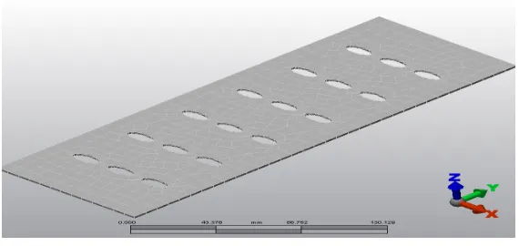
[image:3.612.169.454.198.333.2]2) Generating the Mesh: Generate the mesh for the design Fig.1 shows that a sample meshing of the model and Table no. 1 shows meshing properties
Fig. 1 Meshed Rectangular fin arrays with ellipse perforation TABLEI
MESHING PROPERTIES
Mesh Operation Solid Mesh Final Mesh size 7.9522 mm Elements Created 1636
Mesh Type Mix of Bricks, wedges, pyramids, tetrahedral
3) Assigning Material and Loads to the Meshed Model: Aluminum (Aluminum A380.0-F Die Casting Alloy) has selected for the model due light weight and high heat transfer rate and heat dissipation in this material. The manufacturing process also simple in the aluminum and cost wise it is an economic. The material having thermal conductivity, convection coefficient of heat transfer for air, temperature of surface and ambient temperature as:Thermal conductivity, k = 109 W/m °C, Convection coefficient of heat transfer, h = 6.012 W/m2 °C, Temperature of wall surface at which fin attached, Tb = 100 °C, Ambient temperature, Ta = 30 °C
Fig. 2 Assigning the loads to Rectangular fin arrays.
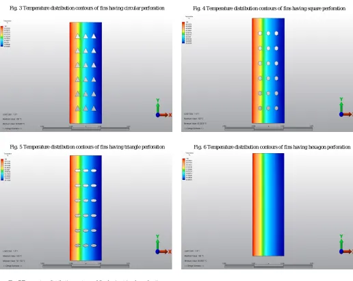
[image:3.612.168.457.515.695.2]distribution along length in fin with circular perforation perforations. Temperature distribution contours of fins having square perforation, triangle perforations, hexagon perforations, and ellipse perforations and without perforations are shown in Figures 4, Figure 5, Figure 6, Figure 7, and Figure 8 respectively.
[image:4.612.56.572.113.272.2]
III.RESULTS AND DISCUSSION
Fig. 3 Temperature distribution contours of fins having circular perforation Fig. 4 Temperature distribution contours of fins having square perforation
[image:4.612.50.566.278.689.2]Fig. 6 Temperature distribution contours of fins having hexagon perforation Fig. 5 Temperature distribution contours of fins having triangle perforation
Fig. 7 Temperature distribution contours of fins having triangle perforation
Nodal temperature distributions of various profiles are found by using analysis software. Temperature distribution at the end of various fin is tabulated as follows
TABLE II
TEMPERATURE AT THE END OF THE FINS
Sr. No Form of Perforation Temperature at the end
1 Circular 82.92 0C
2 Square 82.62 0C
3 Triangle 82.84 0C
4 Hexagon 83.20 0C
5 Ellipse 76.11 0C
6 Non Perforated 83.85 0C
IV.CONCLUSION
Heat transfer is increased by increasing the surface area of extended surface. In finite element analysis, it is found that as the number of perforations increases heat transfer rate increases. Heat transfer rate is found maximum in fin with having ellipse shape perforation. Results of heat transfer rate obtained are quite satisfactory
REFERENCES
[1] Mahmud, A. M. Performance of perforated and Non-perforated Fins, Ph.D thesis Chemical Engineering Dept. University of Baghdad 2005.
[2] Bayram, S. & Alparslan D. Performance Analysis of a Heat ExchangerHaving Perforated Square Fins. Applied Thermal Engineering, 2008, pp 621–632. [3] Kutscher, C.F. Heat Exchange Effectiveness And Pressure Drop For Air Flow Through Perforated Plates With And Without Crosswind, J.Heat transfer,
11(6)1994pp:391-399
[4] Chung, B.T.F. & Iyer, J.R. Optimum Design Of Longitudinal Rectangular Fins And Cylindrical Spines With Variable Heat Transfer Coefficient. Heat Transfer Engineering, 14(1993): 31-42.
[5] Dr. Aziz, M., Mahmud, T. K., Ibrahim, & Jasim, R. R Determination Of The Temperature Distribution The Perforated Fins Under Natural Convection, Tikrit Journal of Eng. Sciences/ 15(2) (20080,(63-78).
[6] Raaid R. Jassem , Effect the form of perforation on the heat transfer in the perforated fins, Academic Research International, Vol. 4 No. 3 May 2013, pp-198-207.
[7] Kumbhar D.G, Dr. N K Sane, Chavan S T, Finite Element Analysis and Experimental Study of Convective Heat Transfer Augmentation from Horizontal Rectangular Fin by Triangular Perforations, PICAME, 376-380, August 3-5, 2009.