Thesis by Yong Hao
In Partial Fulfillment of the Requirements for the Degree of
Doctor of Philosophy
California Institute of Technology Pasadena, California
2007
Acknowledgments
I’d like to express my gratitude to my advisor, Professor David G. Goodwin for his support, encouragement, understanding and seasoned guidance over the years I spent at Caltech for my research and study. This will be one of the most memorable experiences in my life and career.
I am very grateful to Professor Sossina M. Haile and Professor Zongping Shao for sharing their shining thoughts and being wonderful teachers and collaborators during the process of my Ph.D. research. Their diligent work and unique perspectives laid the solid experimental basis for the theoretical work in this thesis.
I’d also like to thank Dr. Carlos Pantano for his suggestions and encouragement. The theoretical work in this thesis benefited tremendously from the discussion with him.
I’m also indebted to my parents for their continuous support and love.
I have been enjoying working with my lab mates David Boyd, Francesco Ciucci, Moh El-Naggar, Jeff Hanna, Eugene Mahmoud, and Vaughan Thomas. It was a lot of fun working with them. Also, thanks are directed to Wei Lai, Calum Chisholm, Kenji Sasaki, Justin Ho, Jennifer Mederos, and Dane Boysen for their discussion. My friends James Endrizzi, Steve Rappel and David Silvey are also the people I’m very thankful to. Their sharing adds so much to my Caltech life and makes it a lot more colorful and enjoyable.
Lastly, I’d like to thank my committee members Professor David Goodwin, Sossina Haile, Melany Hunt and Paul Ronney for their comments and encouragement.
Abstract
Single-chamber solid oxide fuel cells (SCFC) are ones in which the fuel and oxidizer are premixed, and selective electrode catalysts are used to generate the oxygen partial pressure gradient that in a conventional dual-chamber design is produced by physical separation of the fuel and oxidizer streams. The SCFC concept is a novel simplification of a conventional solid oxide fuel cell (SOFC), and SCFCs have been shown capable of generating power densities high enough to make them potentially useful in many applications where the simplicity of a single gas chamber and absence of seals offsets the expected lower efficiency of SCFCs compared to dual-chamber SOFCs.
The model accounts for the coupled effects of gas channel fluid flow, heat transfer, porous media transport, catalytic reforming/shifting chemistry, electrochemistry, and mixed ionic-electronic conductivity. It solves for the velocity, temperature, and species distributions in the gas, profiles of gaseous species and coverages of surface species within the porous electrodes, and the current density profile in an SCFC stack for a specified electrical bias. The model is general, and can be used to simulate any electrode processes for which kinetics are known or may be estimated. A detailed elementary mechanism is used to describe the reactions over the anode catalyst surface. Different design alternatives including flow rates, flow geometry, temperature, optimal fuel to air ratio, anode thickness, YSZ vs. SDC electrolytes, and fuel cell efficiency and fuel utilization are explored. The reaction zones in the anode of an SOFC with hydrocarbon fuel and oxygen addition is also investigated and much deeper insights are obtained compared to the existing literature. Numerical techniques needed for such investigations are also introduced.
Contents
Acknowledgments ………iii
Abstract ………iv
List of Figures ………x
List of Tables………xv
Nomenclature ………xvi
Chapter 1 Introduction 1.1 Overview of Solid Oxide Fuel Cells………1
1.2 Overview of Single-Chamber Solid Oxide Fuel Cells (SCFC) ………4
1.3 Literature Review………6
1.3.1 Research Status in the Single Chamber SOFC Area ………7
1.3.2 Solid Oxide Fuel Cell Modeling ………13
1.3.3 Modeling of Single Chamber SOFC ………18
1.4 Scope of This Thesis ………20
1.4.1 Motivation ………20
1.4.2 Accomplishments ………23
1.5 Organization of This Thesis ………24
1.6 Format Convention ………25
Chapter 2 The Two-dimensional Model for Single-Chamber SOFC 2.1 Background………26
2.3 The Gas Channel Flow Model ………29
2.3.1 Governing Equations and Basic Assumptions ………30
2.3.2 Simplification of the Governing Equations ………33
2.3.3 Boundary Conditions ………36
2.3.4 Non-Dimensionalization of Equations and Boundary Conditions …38 2.3.5 Computation Grid and Discretization ………40
2.4 The Porous Electrode Transport Model ………42
2.5 Heterogeneous Chemistry ………44
2.6 The Electrochemistry Model………45
2.7 The Mixed-Ionic Electronic Conductor (MIEC) Model ………47
2.8 The Conduction and Radiation Model ………49
2.9 Coupling between the Flow Solver and the Chemistry Solver………50
2.10 Numerical Solution Scheme for the Governing Equations of the MEA …52
Chapter 3 Numerical Study of Single-Chamber SOFCs 3.1 Introduction ………55
3.2 Model Calibration and Validation ………56
3.2.1 Structure Parameters of the MEA ………56
Specific Surface Area (SSA) ………57
Electrolyte Conductivities ………58
Porosity, Tortuosity, Pore Radius, and Particle Diameter…59 3.2.2 Parameters for Electrochemistry………60
Asymmetric Factors ………62
3.2.3 Emissivity and Thermal Conductivity ………65
3.2.4 Remarks on the Calibration and Verification Procedure ………67
3.3 Numerical Study of SCFC Performance ………68
3.3.1 Fuel-to-Oxygen Ratio………68
3.3.2 Flow Geometry ………77
Orientation of Single MEA ………77
Interaction between Two MEAs ………80
3.3.3 Anode Thickness ………83
3.3.4 The Influence of Temperature on Fuel Cell Performance ………84
SCFC with YSZ Electrolyte ………85
Anode catalyst selectivity ………86
Exchange current density ………88
SCFC with SDC Electrolyte………91
3.3.5 Flow Rate, Power Output and Efficiencies of SCFC………93
Efficiency and Fuel Utilization versus Fuel Flow Rate ……94
Results at a fixed methane/oxygen ratio ………95
Analysis and improvement ………95
Efficiency and Fuel Utilization at Constant Fuel Flow Rate…99 Result ………99
Analysis………100
Chapter 4 Adaptation of the SCFC Model for Dual-Chamber Fuel Cells 4.1 Introduction ………106 4.2 Dual-Chamber Solid Oxide Fuel Cells……… 107 4.3 Dual-Chamber Solid Acid Fuel Cells ………110
Chapter 5 Advanced Topics
5.1 Introduction ………116 5.2 Reactions Zones in an SOFC Anode with Oxygen Addition ………117 5.3 Simulation of Multi-layer Electrodes ………128 5.4 Automatic Refinement of the 1-D Computation Grid in the MEA ………131 5.5 Concluding Remarks………132
Chapter 6 Conclusions and Future Work
6.1 Conclusions ………134
6.2 Future work ………139
A The Integrated Micro-Power Generator Project ………142 B Comparison of Mass Fluxes Due to Mass Diffusion and Thermal
Diffusion ………145
C Equation Discretization of the Channel Flow Model ………151
List of Figures
1-1 Illustration of a working solid oxide fuel cell [2] ………1 1-2 Solid oxide fuel cell configuration (a) Planar design with fuel and air in
counterflow [3]; (b) Siemens-Westinghouse tubular design [5]………3 1-3 Hibino’s strip configuration SCFC [14]. (a)&(b) unit cell, (c) stack; 1=solid
electrolyte, 2=gold electrode, 3=palladium electrode, 4=gold film as an
interconnector ………7
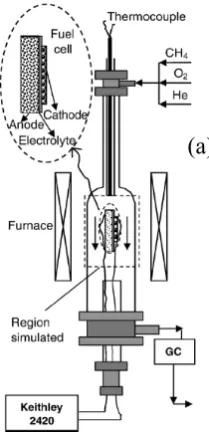
1-4 The operation of a stacked SCFC [6] ………9 2-1 Illustration of the single-chamber fuel cell setup for simulation [10]. (a) A
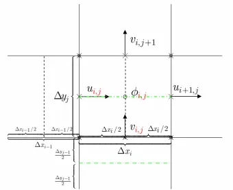
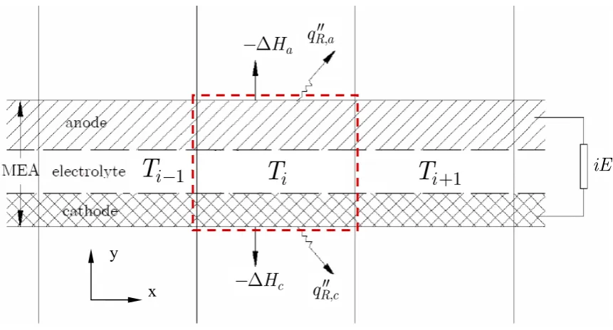
typical experimental arrangement of SCFC (b) The corresponding computational domain of the numerical model. Dashed lines show possible arrangement of cells ………26 2-2 Diagram of the model structure ………29 2-3 The staggered grid of the SIMPLEC algorithm ………41 2-4 Energy balance over a control volume (dashed line) in the cell. cell
temperature; : radiation heat flux; : enthalpy change; iE: power output on external load; subscripts “a” and “c” stand for anode and cathode
respectively. ………49
:
T
R
q′′ ΔH
2-5 Structure of one segment of the MEA and the corresponding
discretization………52
2-6 Structure of the global solution vector for each segment of the
MEA ………53
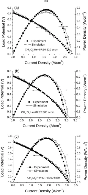
3-2 Simulated vs. experimental polarization curves for CH4, O2 and He flow rates
of 87, 75, and 300 sscm, respectively. (a) Tfurn = 600°C, Tcell = 743°C; (b) Tfurn
= 625°C, Tcell = 763°C; and (c) Tfurn = 650°C, Tcell = 786°C. Simulations
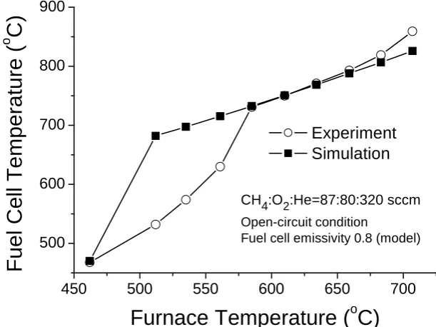
performed isothermally using measured cell temperatures ………64 3-3 Simulated and measured cell temperatures for the operational conditions
indicated ………65
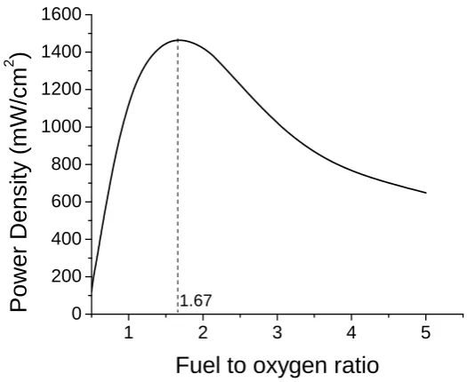
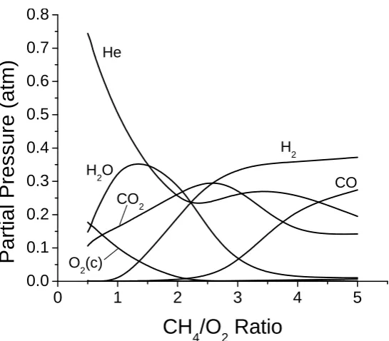
3-4 Simulated power density versus fuel-to-oxygen ratio at 750oC and load potential of 0.5 V; YSZ electrolyte ………71 3-5 Partial pressure of gas species at the anode-electrolyte interface (plus O2 at
cathode-electrolyte interface) at the middle (along x direction) of the fuel cell; T=750oC; Eload = 0.5 V ………72
3-6 Contour plot of local current density (A/cm2) vs. CH4/O2 ratio and location on
the MEA at 750oC and load potential of 0.5V ………74 3-7 Current density along the MEA for different MEA lengths; Flow rate
CH4:O2:He=1:1:4 ………75
3-8 Optimum fuel-to-oxygen ratio of each cell along the MEA for different MEA lengths; Dx: x-dimension of one computation grid ………75 3-9 Two-dimensional distribution of gas phase components in the gas chamber at
opt. fuel-to-oxygen ratio ………76 3-10 Comparison of fuel cell polarization curves for cells placed in different
orientations; a: anode, c: cathode ………78 3-11 Flow geometries for an upstream and a downstream MEA; case 1: base case;
case 2: with inert blocks; case 3: with a narrower channel around the 2nd
3-12 Molar concentration of CH4 and O2 in the gas channel for case 2 …………81
3-13 Figure 3-13. Reaction rates of methane and hydrogen within the anode of the second MEA for case 2 and case 3. (a) methane consumption rate; (b) hydrogen production rate ………82 3-14 Fuel cell power density at 0.4 V and 600°C furnace temperature as a function
of anode thickness………83
3-15 Power density of a YSZ cell at different temperatures and oxygen flow rates. Load potential = 0.5 V; T=750oC ………85 3-16 Reaction rates of the global reaction in the anode at O2 flow rate of 60 sccm
and temperature of 750oC; (a) absolute rate of methane; (b) relative rates of
selected species ………87
3-17 The oxygen partial pressure (a) and exchange current density (b) at the cathode-electrolyte interface along the fuel cell at different temperatures; O2
flow rate: 60 sccm………89
3-18 The partial pressures of (a) H2 and (b) H2O at the anode-electrolyte
interface………90
3-19 Performance of an SDC cell at different temperatures and oxygen flow rates. Load potential = 0.4 V, T=750oC; (a) Power density; (b) Electronic current
density ………92
3-20 Power output and efficiencies of a YSZ cell at different methane flow rates with a fixed ratio of CH4:O2:He = 1:0.8:3.2; T=750oC; E=0.5 V …………94 3-21 Conversion percentages of methane and oxygen at different methane flow
3-22 LHV efficiency and fuel utilization of a YSZ cell at different O2/CH4
ratios ………97
3-23 Fuel utilization εU and current density as functions of load
potential………99
3-24 Yield percentage of gas-phase product species as functions of load potential. CO and CO2 are based on C balance; H2 and H2O are based on H
balance………100
3-25 Selectivity percentage of gas-phase product species as functions of load potential. CO and CO2 are based on C balance; H2 and H2O are based on H
balance………101
4-1 Schematic diagram of a dual-chamber SOFC in the button-cell configuration. A: anode; C: cathode; E: electrolyte ………107 4-2 Discharge characteristics of a dual-chamber SOFC with moisturized H2
fuel ………108
4-3 Discharge characteristics of a dual-chamber fuel cell running on methane with small oxygen addition in the anode chamber ………109 4-4 Conductivity of polycrystalline CsH2PO4 versus temperature [85] ………111
4-5 Comparison of discharge characteristics of a solid-acid fuel cell. (a) Original; (b) I-R corrected ………113 4-6 Simulated charge transfer overpotential at the cathode-electrolyte
interface ………114
4-7 Simulated charge transfer overpotential at the anode-electrolyte
5-1 Concentration and net production rates of gas species in the anode of a single-chamber SOFC at open-circuit condition ………122 5-2 Concentration and net production rates of gas species in the anode at 0.5
V ………125
5-3 Concentrations and net production rates of gas-phase species in a
dual-chamber SOFC anode ………127
5-4 Maximum power density of a single-chamber SOFC with Ni-Pt composite anode versus Pt layer thickness ………129 5-5 Schematic illustration of the computational domain of an MEA with (a)
List of Tables
2-1 Boundary Conditions for the Gas Channel Flow Model ………37
2-2 Basic Parameters for Nondimensionalization of Governing Equations ……38
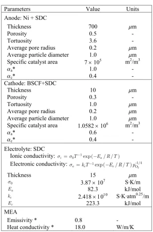
3-1 Parameters for a Ni-SDC|SDC|BSCF-SDC MEA obtained through model calibration ………66
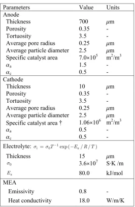
3-2 Parameters for an SCFC MEA Structure with YSZ electrolyte ………69
4-1 Parameters for the simulation of a solid acid fuel cell ………113
B-1 Comparison of and Dk m, DTk at the gas channel inlet (N2) ………146
B-2 Comparison of and Dk m, DTk at the gas channel outlet (N2) ………146
B-3 Comparison of and Dk m, DTk at the anode-gas interface (N2)………147
B-4 Comparison of and Dk m, DTk at the cathode-gas interface (N2) ………147
B-5 Comparison of and Dk m, DTk at the gas channel inlet (He) ………147
B-6 Comparison of and Dk m, DTk at the gas channel outlet (He) ………147
B-7 Comparison of and Dk m, DTk at the anode-gas interface (He)………148
Nomenclature
Latin Lettersc
A Specific surface area of a porous medium
p
c Specific heat at constant pressure
p
d Particle diameter
,
k m
D Mass diffusion coefficient of gas species k in a gas mixture
T k
D Thermal diffusion coefficient of gas species k
0
E Nernst potential E Load potential F Faraday’s constant
k
h Enthalpy of species k
i
i Ionic current
e
i Electronic current
tot
i Total current
j Current density
0
j Exchange current density
k
j Mass flux of gas species k
e
L Electrolyte thickness m Mass flow rate
sp
N Total number of gas phase species
surf
N Total number of surface phase species p Pressure
R, Rg Universal gas constant
Re Reynolds number
Sc Schmidt number
k
s Molar production rate of species k over the catalyst surface
T Temperature
u Velocity vector
u x-component of the velocity field
v y-component of the velocity field W Molecular weight
W Mean molecular weight
k
X Molar fraction of species k in a gas mixture
k
Y Mass fraction of species k in a gas mixture
Greek Letters
a
α Anodic asymmetry factor of the Butler-Volmer equation
c
α Cathodic asymmetry factor of the Butler-Volmer equation
ε Emissivity
U
ε Fuel utilization
φ Porosity of a porous medium or a general scalar
η Overpotential or fuel cell efficiency
λ Thermal conductivity
μ Dynamic viscosity
θ Dimensionless temperature or coverage percentage of surface species
e
σ Electronic conductivity
i
σ Ionic conductivity
τ Tortuosity of a porous medium
k
ω Molar production rate of species k
Operators
∇ Nabla operator
Δ Difference operator
Acronyms
ASR Area-specific resistance
BET Brunauer-Emmett-Teller (method) BSCF Ba0.5Sr0.5Co0.8Fe0.2O3-d
CFL Courant-Friedrichs-Lewy (condition) LSGM La0.9Sr0.1Ga0.8Mg0.2O3
MEA Membrane electrode assembly OCV Open circuit voltage
SDC Ce0.8Sm0.2O1.9
Chapter 1
Introduction
1.1Overview of Solid Oxide Fuel Cells
Fuel cells are a type of highly efficient energy conversion device that directly
produces electricity from external supplies of fuel and oxidant. They produce power
without combustion or rotating machinery, and work continuously as long as the fuel
supply is maintained. Fuel cells offer the prospect of silent electrical power generation
at high efficiency with near-zero emission of pollutants. Fuel cells are not subject to
the Carnot limitation and their theoretical maximum efficiency based on the chemical
exergy of the fuel is close to 100%. The efficiencies of currently operating systems
are in the range of 40–60% but they have the potential to achieve higher values,
[image:19.595.139.452.490.724.2]particularly with hybrid configurations where a high-temperature fuel cell replaces the
combustor of a gas turbine [1].
Fuel cells are often classified by electrolyte. Among them, solid oxide fuel cells
(SOFC) utilize ceramic materials that conduct oxygen ions (e.g., yittria-stabilized
zirconia, YSZ) as the electrolyte layer and usually operate at high temperature
(600-1000oC) for the electrolyte to have sufficient ionic conductivity. Fig. 1-1 shows the
working principle of an SOFC, in which oxygen is reduced on the cathode side and
hydrogen and carbon monoxide are oxidized on the anode side simultaneously by
electrochemistry.
Compared with other types of fuel cells, solid oxide fuel cells have many
advantages. The high temperature increases the potential for high system efficiency.
Conversion efficiencies of SOFC can be considerably greater than those of heat
engines, with hybrid cycles in combination with heat engines and co-generation
promising conversion efficiencies greater than 70% [3]. Solid oxide fuel cells can
operate on hydrocarbon or hydrocarbon-derived fuels directly [3] and have the widest
range of fuels. Furthermore, because SOFCs operate at such high temperatures, direct
internal reforming of hydrocarbon fuels becomes particularly attractive, because the
heat released by the electrochemical reaction is partially used to supply the
endothermic reforming process. Therefore, the fuel processing can be integrated with
the fuel cell stack, and catalyst particles in the anodes reform the fuel into H2 and CO
for direct electrochemical conversion [1]. Meanwhile, SOFCs are tolerant to gas
contaminants normally considered “poisons” (e.g., CO) for lower temperature fuel
electrochemistry in SOFCs. The indirect route is by way of the water-gas shift
reaction to convert CO to H2, and it generally exceeds the direct utilization of CO by
electrochemistry [1]. The tolerance to CO eliminates the need for noble metal for
electrodes (e.g., Pt) and lowers fabrication cost.
On the other hand, the high operating temperature also leads to drawbacks such as
long startup time, small number of thermal cycling (i.e., heating up and cooling down)
and stringent requirement on both materials and manufacturing processes. In addition,
the mechanical shock resistance is low, particularly for the conventional
dual-chamber configuration. Moreover, the application of SOFCs for propulsion (for
transportation purposes) and portable power generation are still very limited. All these
drawbacks require additional research.
Based on design geometries, solid oxide fuel cells are categorized as planar and
tubular. Fig. 1-2a shows a typical planar SOFC design with fuel and air in
counter-flow. Co-flow and cross-flow designs are also possible in order to supply the fuel and
oxidant in the most efficient manner, and also to minimize temperature gradients
within the stack [1]. The major problem with planar SOFCs (both single cell and
stacks) is the cracking of the sealing material due to thermal cycling.
The tubular design (Fig. 1-2b) was first developed by the Westinghouse company
and does not have the sealing problem. One end of the fuel cell is closed, providing an
integral return for the air introduced from the other end through a concentric tube. The
tubular design is the most advanced and applies in large commercial and industrial
cogeneration areas. The technical challenge with tubular SOFC stacks mainly lies in
the flow management.
1.2Overview of Single-Chamber Solid Oxide Fuel Cells (SCFC)
Most of the SCFCs being studied belong to the planar SOFC category. It is a
novel type of SOFC in which the anode and cathode are both exposed to the same
premixed fuel/air stream, and selective electro-catalysts are used to preferentially
oxidize the fuel at the anode and reduce oxygen at the cathode [6]. It operates in a
mixture of hydrocarbon fuel and oxygen in which the amount of oxygen is less than
that required for complete combustion of the fuel. This is called the fuel-rich
condition and is required to produce hydrogen and CO (i.e., syngas) without
producing significant amounts of CO2 and H2O. At the anode, selective catalysts
result in in-situ catalytic reactions (e.g., partial oxidation and reforming) of the fuel to
produce the syngas, which are then electrochemically oxidized by reaction with
reduced to replenish the oxygen ions in the electrolyte lost on the anode side, with a
net flow of current through the electrolyte and in the external circuit.
In an SCFC, the chemical (or electrical) potential gradient across the cell, i.e., the
driving force for the electrical current, is generated by the oxygen partial pressure
gradient due to the selectivity of the electrode catalysts for different catalytic reactions,
rather than by physically separating the fuel and oxygen as in the conventional
dual-chamber design. As a consequence, the need to maintain gas-tight anode and cathode
chambers is eliminated and the fuel cell design is greatly simplified. In fact, the SCFC
not only gets rid of the sealing, but even allows for a porous electrolyte [7]. Recent
studies showed that SCFC with porous electrolytes could also deliver high
performances [8]. This allows relatively low processing temperature of the electrolyte
and thus reduces the manufacturing cost [9].
The need for selective electro-catalysts has several implications for the design of
an SCFC. First of all, an SCFC must operate at a temperature low enough that the
catalysts maintain some degree of selectivity; this typically limits the temperature to
below 700oC, which is significantly lower than that of conventional SOFCs with a
YSZ electrolyte. For this reason, SCFCs demonstrated to date have used ceria-based
electrolytes, rather than YSZ [6]. The relatively low temperatures (400-600°C) at
which the most advanced SCFCs function also help to ease complications with on-off
cycling. The reduced temperatures of operation provide additional benefits including
expanding the choices of materials for fabrication of peripheral components and
Meanwhile, the low temperature also reduces the possibility of explosion of the
fuel-air mixture. For example, the ignition temperature of methane is higher than 1000oC,
especially over Ni and Pt surfaces [11], and therefore SCFCs with methane fuel can
avoid this problem when operated in the reduced temperature range.
Another implication of the need for selective electro-catalysts is that an SCFC is
unlikely to run well, if at all, on hydrogen. Any catalyst that promotes electrochemical
oxidation of hydrogen, or electrochemical reduction of oxygen, would very likely
promote direct catalytic combustion if exposed to a hydrogen/air mixture. This
problem can be dealt with by using a hydrocarbon fuel instead of hydrogen, as has
been done in all successful demonstrations of SCFC operation. With a hydrocarbon
fuel, catalytic partial oxidation and reforming chemistry can be used within the anode
to deplete incoming oxygen, creating a reducing environment deep within the anode
near the electrochemically active layer, and to generate hydrogen needed for the
electrochemistry in situ, very near where it is consumed in the electrochemical
oxidation reaction. Similarly, at the cathode, if hydrogen generation via hydrocarbon
cracking can be suppressed, parasitic combustion at the cathode may be minimized
[6].
1.3Literature Review
Before starting the discussion about the modeling work on SCFC, it is important
to review the research status in both experiment and modeling in this area. The
both the advances in SCFC studies (mostly experimental) and the existing modeling
research on SOFC systems in general. Existing challenges are listed at the end of this
section.
1.3.1 Research Status in the Single Chamber SOFC Area
The SCFC was conceptually proposed by researchers in 1965 [12], and the first
application of this concept to SOFCs was made by Hibino et al. in 1993 [13]. So far,
research in this area has been mostly experimental, with most advances in the fuel cell
performance resulting from improvement with the materials of both electrodes and the
electrolyte, especially in early studies.
(a) (b) (c)
Figure 1-3. Hibino’s strip configuration SCFC [14]. (a)&(b) unit cell, (c) stack; 1=solid electrolyte, 2=gold electrode, 3=palladium electrode, 4=gold film as an interconnector
Hibino first proposed the strip configuration (later called the B-type, Fig. 1-3) fuel
cell operated in a mixture of methane and air. In this configuration, the two electrodes
(gold cathode and palladium anode in this case) are fabricated on the same face of the
ceramic electrolyte (BaCe0.8Gd0.2O3-s in this case), and the distance (Fig. 1-2b)
between them varies. The discharge characteristics generally improve as the distance
for this type of SCFC is an inter-digitated comb-shape array in which the two
electrodes face each other in close proximity [14].
Despite the advantage of being compact, the design of this type of SCFC also puts
some inherent limitations on its performance. First of all, although the distance
between the two electrodes plays an important role in the overall ohmic resistance
between them, the resistance also goes up with the width of the electrodes [14],
limiting the width itself and thus the total catalyst surface area for both the production
of syngas (i.e., H2 and CO) and reduction of oxygen. Secondly, the electrical
performance is hindered by the gas-phase diffusion of syngas from the anode to the
cathode and the combustion of the syngas over the cathode catalyst surface. This not
only requires a careful control of the flow direction, but also requires the two
electrodes not be too close to each other, keeping the ohmic resistance from further
reduction. Lastly, the electrodes are sputtered onto the electrolyte plate so as to
maximize the electrode area and to minimize the conduction path of the charge carrier
[15], thus limiting their thickness and thus the production of the syngas. More
importantly, the thickness is unlikely to be increased significantly due to
considerations in both fabrication and the gas-diffusion of syngas given the closeness
of the electrodes.
For reasons stated above, the majority of recent studies about SCFC focus on the
stacked configuration (also called type-A SCFC by Hibino et al.) instead (Fig. 1-4), in
which the electrodes are on different sides of the electrolyte. Although the cell could
Figure 1-4. The operation of a stacked SCFC [6]
anode-supported cell is of particular interest due to its high performance. The latest
design of such cells typically involves a thick nickel-based anode (of the order 1 mm),
a ceria-based electrolyte with high ionic conductivity, and a perovskite cathode (e.g.,
Sm0.5Sr0.5CoO3, SSC) with high oxygen-reduction capability. The thick anode not
only provides enough surface sites for the reforming and partial oxidation of the
hydrocarbon fuel for the production of syngas for electrochemistry, but also brings the
additional advantage of a significant temperature increase due to the catalytic
oxidation of the fuel (discussed later in the thesis). In addition, the separation of the
electrodes benefits the performance in two ways. First, it makes it more difficult for
the syngas to diffuse from the anode to the cathode, thus reducing the parasitic
combustion at the cathode. Second, the ohmic resistance of the electrolyte can be
significantly reduced by using very thin layers, which is only limited by its own
mechanical properties. For these reasons, the anode-supported SCFC in the stacked
configuration delivers much higher power density compared with the cells in the strip
configuration. Peak power densities of ~ 650, ~ 400 and ~ 440 mW/cm2 have been
The stacked configuration of SCFC has some characteristics that make it
particularly suitable for micro-scale power generation. The Integrated Micro-Power
Generator Project is one example. The readers are referred to Appendix A for more
details. The anode-supported SCFC in stacked configuration is the topic of this thesis.
It needs to be pointed out that the efficiency of the SCFC is typically much lower
than the dual-chamber SOFCs (see Chapter 3). However, the goal of the SCFC study
is to compete with lithium batteries in terms of total power output, and the low
efficiency can be compensated by the high energy density of hydrocarbon fuels
mentioned in Appendix A.
The development of SCFC generally proceeds with innovations in materials for
cell components with gradually-expanding scope of other parameters, leading to a
general trend of lower temperature, higher power density, and more comprehensive
consideration in design. Before 2002, major advances were made by Hibino’s group
with the stacked configuration, focusing on the materials side. Their investigations
were usually performed with fixed operating conditions including temperature, gas
flow rates, and flow field geometry. Hibino’s earliest SCFCs used Pt as the anode and
Au as the cathode [16]. The performance was poor partly because Pt is a well-known
combustion catalyst for methane and thus the selectivity for generating hydrogen is
low, partly because the electrolyte resistance is high, and partly because both
electrodes are relatively dense. The first significant improvement was made by adding
MnO2 to both electrodes and the electrolyte, which lead to remarkable increase in
reducing electrode reaction resistances. The next breakthrough came with the
adoption of Ni anode and La0.8Sr0.2MnO3 (LSM) cathode [12], which are much better
than the Pt-Au electrode pair. Both open circuit voltage (OCV) and maximum power
were greatly improved.
This was succeeded by a dramatic reduction of operating temperature from 950oC
to 500oC, achieved through the employment of electrolyte materials with high ionic
conductivity and reduction of electrolyte thickness [17]. Samaria-doped ceria (SDC),
a mixed ionic-electronic conducting material, was used instead of YSZ, and the
minimum thickness was reduced from 0.5 mm to 0.15 mm, significantly reducing the
total ohmic resistance. The ceria electrolyte also resulted in a much smaller electrode
reaction resistance, explained by the promotion of the rate of the rate-limiting charge
transfer reaction at the triple-phase (gas-electrode-electrolyte) boundary through the
increase of ionic conductivity. In this study, the ethane fuel also contributed to the
lower temperature since it is less stable than methane used in previous studies. The
reported maximum power density of 403 mW/cm2 (at 500oC) was much higher than
the 121 mW/cm2 (at 950oC) previously reported with YSZ electrolyte.
The fuel cell performance was further improved in terms of lower temperature and
higher power density by doping Pd in the Ni-SDC anode, with the same thinking of
SDC electrolyte and higher hydrocarbon fuel inherited. With the Pd-doped Ni anode
and Sm0.5Sr0.5O3 (SSC), the SCFC could operate at temperatures as low as 450oC, and
the maximum power reported at 550oC was 644mW/cm2 [18]. On the other hand, the
Since 2004, many researchers have started to expand the parameter set for study,
along with the materials. Shao et al. studied SCFC from perspectives including
material, temperature, flow geometry, fuel type, and fuel/air ratio. They first reported
Ba0.5Sr0.5Co0.8Fe0.2O3−δ (BSCF) as a new cathode material for both single- and dual-
chamber SOFCs at reduced temperatures, and the BSCF cathode with a 30wt% SDC
was in the best favor for SCFC at reduced temperatures due to its inactivity towards
the oxidation of hydrocarbon fuels and the extraordinary oxygen vacancy diffusion
rate compared with previous cathode materials [9, 20]. They also reported operating a
two-cell stack without external heating in a propane-oxygen-helium mixture. The
anode-facing-anode geometry that they proposed resulted in a combined power
density more than twice as much as that of a single cell, and the total power output
was 0.35 W at the cell temperature of 580oC. They also demonstrated that fuel cell
power improves with flow rates. The fuel cell was tested in the temperature range of
400 to 700oC, with the ideal oxygen/propane ratio measured to be about 2.5 to 3.0 [9,
21]. They recently reported the power density of an SCFC running with methane to be
as high as 786 mW/cm2 [22], which is the highest in literature so far.
Other important results were reported by Stefan et al. about flow geometry [23],
Suzuki et al. about both materials [8, 24–26] and flow rate [8], and Napporn et al.
about flow rate [27] and actual fuel cell temperature [28]. Specifically, Stefan et al.
reported that the fuel cell geometry that exposes the cathode to the incoming gas feed
delivers a better performance than the case when the cell is flipped by 180 degrees.
1.3.2 Solid Oxide Fuel Cell Modeling
Another important background of this work is the numerical modeling of SOFCs.
For the convenience of discussion, the model classification will be discussed first.
Depending on the type of questions they address and the type of assumptions they
make, the existing models in literature can be classified according to different criteria.
Based on the number of dimensions that they simulate, the models can be classified as
one-, two-, and three-dimensional [29–33]; based on the necessity to resolve temporal
evolution, they can be classified as transient [33, 34] and steady-state models [35, 36];
based on length scale, they can be classified as system-level [33], cell-level [37–39],
and component-level models [32, 40, 41]; based on geometry, they can be categorized
as planar [33, 42] and tubular [35, 43].
The discussion in this section will be based on the length-scale categorization
since it best described the work presented in this thesis. However, a review about
different ways to classify the models will be informative and could provide useful
insights. So other classification methods will also be discussed here based on their
application on different length scales.
First of all, the geometric classification is mostly useful on the system level,
describing the macroscopic flow and heat transfer management and their influence on
the fuel cell performance, and thus it largely falls in the category of system-level
modeling. Since the general forms of underlying governing equations for flow and
and the geometric classification can be combined into the discussion on system-level
modeling.
Secondly, as for the temporal classification, the majority of the existing models
are steady state, especially (but not only) those for system-level fuel cell
performances including voltage and power. The transient models are mostly
impedance spectrum models (e.g., [34]) on the MEA (membrane-electrode assembly)
level and the component level, plus a very few system-level models with the need to
simulate time-response of the system [33]. Although the steady-state models can be
formulated in a transient form, in most cases the time evolution is not of interest, and
the computation with time being a true variable can lead to various numerical issues
(e.g., stiffness of partial differential equations) and reduce the computation efficiency.
So for the work in this thesis, the temporal classification is not truly necessary, and
the steady-state models are of interest. They can be combined with the discussion
about models at different length scales.
Lastly, the number of dimensions that a model takes really depends on the focus
and the requirement to resolve the questions under consideration, and is not
necessarily connected with the length scale that the model is designed for. Although
many system-level models are 2D or 3D, a lot of useful insights (e.g., fuel cell
efficiency) can still be obtained by 1D system models [29] when the
multi-dimensional effects are not important; on the other hand, although many MEA models
are formulated in a 1D form [37], the number of dimensions do need to be increased
structures and effects [32, 44]. Furthermore, a multi-scale model can employ different
number of dimensions at different length scales based on the needs mentioned above
and on the consideration of computation efficiency. For example, it’s not an unusual
practice to assume 1D electrochemistry in many 3D system-level models [35]. Bove
et al. [45] give a brief review on SOFC modeling approaches with different
dimensions.
Phenomena in fuel cells relate to many disciplines from materials science through
electrochemistry, catalytic chemistry, and heat and mass transfer, to fluid mechanics
[1]. A fuel cell model should, depending on needs, involve one or more of these areas
in a coupled way. On the system level, many models have modules to simulate the
fluid flow and/or heat and mass transfer because the distribution of gas reactants,
temperature, and flow geometry can often significantly affect the fuel cell
performance. For example, the 3D model by Achenbach [33] showed the importance
of heat transfer in an SOFC stack; comparatively small temperature variations can
have significant effects on the reaction kinetics, ionic conductivity, and Nernst
potential [1]. In the simulation of the multi-component flow, the governing equations
for the conservation of mass, momentum, and energy gas are usually solved together
[33, 46] by some implicit numerical scheme. This is called “thermofluid modeling” by
some researchers [1]. Some groups make simplifications by simulating the system at
presumed (e.g., uniform) flow field [47, 48] or at uniform temperatures, while most of
the recent large-scale flow calculations fully resolve the flow with commercial CFD
allows the user to incorporate his own model via “user-defined functions” [1]. Ma et
al. [53] give a review of the use of CFD in fuel cell applications.
Despite the different approaches for thermofluid modeling on the system level, a
few points need to be stressed. First, modeling of flow and heat transfer is eased by
the fact that flow in SOFCs is usually laminar [1]. Second, gas-phase chemistry is
typically neglected since most SOFCs run on hydrogen (for dual-chamber only) or
methane (both single- and dual-chamber), and for the hydrogen case it doesn’t exist
because in dual-chamber SOFCs, hydrogen and oxygen are physically separated,
while for the methane case the operating temperature of SOFCs (below 1000oC) is
typically too low for the gas-phase reaction of methane to be significant [1, 54].
However, for SOFCs running on higher hydrocarbons (e.g., propane), gas-phase
chemistry may be important and needs to be simulated by some readily-developed
reaction mechanisms. Third, many models assume constant gas properties such as
density and diffusion coefficient, which is an oversimplification since the variation of
component and temperature can be very large, and accurate representation of the
properties of high-temperature gas mixture is not straightforward [1]. Fourth, if the
effect of temperature variation is ever going to be considered in a model, radiation
heat transfer should not be neglected, since at the operating temperature of most
SOFCs, radiation accounts for a significant portion of the heat transferred and thus
sensitively influences the temperature.
Models at the MEA level typically involve modules describing the diffusion and
boundary condition. Although it is well known that the electrochemically active
region extends at least 10 mm into the porous electrode [55], and there are existing
models at the component level about the detailed structure and processes about the
electrodes [44] and the electrode-electrolyte interface [32], the approximate treatment
of the electrochemistry often leads to satisfactory prediction of overall performance.
Most models represent the electrochemistry by the Butler-Volmer equation, although
some study shows that for charge-transfer processes that include more than one step,
the values of the asymmetry factors can be greater than 1 [56]. The objective of the
diffusion model is to supply the anode with hydrogen and cathode with oxygen, and
to remove the reaction product water, while minimizing the concentration difference
across the porous electrodes [1]. Accurate ways to simulate the multi-component
diffusion process include the dusty gas model (DGM) [37, 57] and the mean pore
transport model (MPTM) [58]. Young [1] gives a detailed comparison between these
two approaches. The work in this thesis uses the dusty gas model. As for the reaction
modeling with hydrocarbon fuels, especially methane, many papers [47, 52] use a
global description of the reforming and water-gas shift reactions with constant-rate
constants, and some even use pre-reformed fuel [59]. Needless to say, such treatment
of the reaction is very rough and does not provide a sound basis for quantitative
prediction. Recently, Deutschmann et al. developed a multi-step, elementary reaction
mechanism to describe steam-assisted catalytic partial oxidation of methane in
small-channel monolith reactors using Ni supported on alumina [60]. The reliability of the
[61] and used in several models demonstrating with good quantitative agreement with
experiments [50, 56]. The work in this thesis employs the same reaction mechanism
to study the heterogeneous reactions in the porous Ni anode of an SOFC.
Lastly it’s worth pointing out that all SOFC models have to be validated by
careful experimentation. Otherwise, a prediction is only as good as the underlying
physical modeling [1].
1.3.3 Modeling of Single Chamber SOFC
The modeling of single-chamber SOFC is similar to the modeling of
dual-chamber SOFCs in many ways. However, there are still a few major differences based
on the review of SCFC above. First of all, the flow model needs to be at least
two-dimensional, since experimental research has shown the importance of flow
management by way of geometric design. Secondly, the anode reaction is more
complicated than the dual-chamber case, due to the mixing of fuel and oxygen. This
requires that a detailed reaction mechanism be used. Thirdly, due to the mixing of fuel
and air as well as the gas-phase diffusion from anode to cathode, an experimental
oxidation reaction mechanism of the hydrocarbon fuel and the syngas (i.e., hydrogen
and CO) is needed on the cathode side. Lastly, since the temperature increase of the
fuel cell is much more significant than dual-chamber SOFCs, radiation must be an
integral part of the model.
Besides the work presented in this thesis and published papers [6, 10], the only
al. [51, 62] in parallel with the experimental research by Ahn et al. [63, 64] about the
strip configuration, which is different from the focus of this work. That model is able
to calculate the polarization curves of the fuel cell and make some qualitative
conclusions for improvement of the experimental design. The strength of Chung’s
work is that it resolves the three-dimensional flow field around the fuel cell with the
commercial finite element package FEMLAB. The simulation of the 3D flow field is
necessary for the understanding the flow and mass transport problems in such a fuel
cell system.
However, Chung’s model is still far from enough to make any prediction of the
fuel cell on a reliable basis due to the limitation imposed by the capability of the CFD
software, oversimplifications in the model development, and lack of experimental
validation. Compared with other CFD packages particularly designed for fluid
dynamics and heat transfer, the FEMLAB software is quite primitive. Constant gas
properties including density, viscosity, and diffusivity have to be assumed. Another
significant drawback with the model is that it lacks the critical capability to simulate
the diffusion and reaction of methane in the porous anode. This results in a mixture of
hydrogen and air, which is never possible for SCFCs. Besides, although the model
claims to have the capability to simulate “ceria”-based SCFCs [51], it does not
actually involve the simulation of mixed electronic-ionic conduction.
Based on the literature review above, it can be seen that although the current
status of SOFC modeling provides enough capability to model most aspects of SCFCs,
SCFC and the dual-chamber SOFCs. Currently the experimental research in the SCFC
area needs much more guidance from modeling, which is the motivation of this work
and will be discussed below.
1.4 Scope of This Thesis
The motivation section describes the current challenges in the stacked SCFC
development and objectives for this work, followed by a section showing the
accomplishments that the model has achieved so far.
1.4.1 Motivation
SCFC development has proceeded primarily via experimental optimization of the
multiple parameters relevant to the power output, and important ones such as the
selectivity of the electrodes, have received considerable attention in research.
However, although very respectable power densities have been demonstrated
experimentally, it is not at all clear that present designs are close to optimal, or that
the measured performance for a single cell translates to performance in a stack.
Besides the selectivity of the electro-catalysts, there are many other factors that
influence SCFC performance for both unit cells and cell stacks. For example, at the
atomistic level, the performance of a unit cell is dictated by the interplay of a variety
of physical or chemical processes, including surface chemistry on the anode and
cathode, heat transfer, transport of the gaseous reactants and products within the
mesoscale, the cell performance is found to sensitively depend on the system fluid
mechanics (e.g., cell orientation relative to the flow), species transport, and
competition between various modes of heat transfer. On the cell-stack level, hydrogen
generated within one anode might diffuse to the cathode of an adjacent cell where it
burns, or, if some cells are placed downstream of others, depletion of fuel or oxygen
may strongly affect performance. Assessing the potential performance of a SCFC
stack design requires considering all these complex effects for both unit cells and the
stack.
Despite the obvious importance of these design issues, current experimental
research is limited by the lack of effective research tools, particularly diagnostic tools
for micro-scale physical and chemical processes, which are crucial for the cell
functionalities. Most experimental groups have to take the relatively inefficient
trial-and-error loop to improve their cell design, which makes the systematic study and
optimization of design parameters tedious and cost-prohibitive.
The design needs of SCFC thus require a comprehensive numerical model that can
simulate all the important processes in the fuel cell and can provide fundamental
insights into the design tradeoffs. Due to the reasons stated above, the model should
not only be able to treat each individual process, but should also handle the coupling
among the important ones, including channel flow transport, catalytic surface
chemistry, electrochemistry, heat transfer, ionic conduction, and porous media
transport within the electrodes of each cell. The simulation of the single-chamber
configurations, where the flow in the gas channels may be treated as a plug flow. In
the absence of defined gas channels, the flow and transport processes must be treated
using a multidimensional formulation and a model of at least two-dimension is needed.
This work presents a two-dimensional numerical model about the
anode-supported SCFC in the stack configuration. Besides a large design parameter space
and the popularity of this type of cell in experimental research, the relatively simple
representation of the cell and external flow compared with the strip configuration is
also an important motivation of this work. In the stacked configuration, due to the
high aspect ratio of the cell, the transport processes in the electrodes and the
electrolyte can be well modeled locally as one-dimensional; the relatively weak lateral
diffusion compared with the dominant channel flow means that the flow around the
cell can be well simulated with a two-dimensional model. Therefore, a model of 2D is
considered sufficient for describing this type of SCFC. Also, due to considerations of
computation cost and efficiency, a lower-dimensional model is preferred as long as
the fundamental principles can be captured.
In addition, many other fuel cell designs, such as the tubular SOFC and the planar,
dual-chamber SOFC in the button-cell configuration can be sufficiently described by
a 2D model. These add to the motivation for this work to develop the model into a
general framework that can simulate such fuel cell systems.
The major purpose of this work is to answer important design questions for SCFC
systems such as optimization of design parameters especially in the realm that
performances for both unit cell and cell stacks. Through the combined effort of
experiment and simulation, the design process of SCFC systems can be greatly
accelerated and the development cycle can be significantly reduced. In addition,
important issues for the design of planar dual-chamber SOFC and tubular SOFC are
also discussed.
1.4.2 Accomplishments
This work is the first numerical model of the stacked SCFC systems based on first
principles and calibrated on a physical basis. Deep insights in catalytic chemistry,
electrochemistry, flow convection, heat transfer, and mixed conducting are obtained.
The simulated electrical performance shows good agreement with experimental
results.
The model has been applied to optimization design of both single SCFC and
SCFC stacks, and reasonable results have been obtained. It is very difficult to
accurately explore these optimization issues experimentally, but the model prediction
provides reliable theoretical basis for further improvement in experiment without the
trial-and-error design cycles.
The model is able to simulate the planar SOFC in the single- and dual-chamber
configurations, and can also be adapted to simulate the tubular SOFC after minor
changes. It allows a great flexibility in defining the two-dimensional flow geometry
The model can simulate the SCFC performance with a much wider range of
design parameters than allowed in actual experiment. This leaves enough room for
design optimization of the SCFC system.
Although methane is the major fuel under investigation in this work, the model
can actually simulate SCFC running on any hydrocarbon fuel provided that the
partial/full oxidation mechanism in the electrodes is available.
1.5Organization of This Thesis
In Chapter 2, the numerical model is discussed in detail, including the governing
equations, boundary conditions, and the numerical schemes to solve the problems in
both the flow channel and the MEA.
In Chapter 3, the calibration of the model based on experimental measurements is
presented; followed by the prediction of the model for SCFC performances compared
with experimental results; and the exploration of many important design parameters
such as the optimum fuel-to-oxygen ratio in the SCFC design.
In Chapter 4, the application of the model to planar dual-chamber fuel cells with
either oxygen ion conductor or proton conductor electrolyte is discussed.
Chapter 5 discusses some advanced topics, such as the three-layer structure of
reaction zones in an SOFC anode and the design of a multi-layer anode for SOFC
with oxygen addition in general. The automatic refinement of a computational grid for
the fuel cell is also discussed.
1.6 Format Convention
Texts in each chapter are usually divided into subheadings of different levels. The
first-level subheadings have the format of “1.1” and the second level is formatted
“1.1.1.” Third and fourth level subheadings are also used in some chapters, with the
third level using italic fonts and the fourth level using underlined italic fonts.
As for the bibliography, the title of references (including papers and books) is
shown in italic fonts. The volume that each technical paper belongs is emphasized
with bold font, followed by the number of the starting page and the year of
Chapter 2
The 2D Model for Single-Chamber SOFC
2.1 Background
The numerical model was developed in collaboration with the experimental
research in Haile’s group at Caltech into the stacked anode-supported SCFC. The
model is based on first principles that govern the operation of the fuel cell, and is
tailored to the requirements of the experimental design. Important parameters of the
model are calibrated by the experimental measurement of the fuel cell performance,
and comparison between the model prediction and independent experimental
measurement is used to examine the validity of the model. The theoretical part of the
model development is discussed in this chapter, and the model calibration and
prediction are discussed in the next chapter.
(b)
(a)
(b) The corresponding computational domain of the
numerical model. Dashed lines show possible arrangement of cells
[image:44.595.111.216.490.709.2](a) A typical experimental arrangement of SCFC
The experimental setup of a typical single-chamber fuel cell is shown in Fig. 2-1a.
The premixed gas stream (oxygen + methane + helium) is supplied through the top of
the reactor and the cells are placed either parallel or perpendicular to the streamwise
direction. The reactor is surrounded and heated by a tube furnace. Within the porous
anode, H2 is generated through the direct and indirect reactions of methane with
oxygen and water (due to electrochemistry) and oxidized electrochemically over a
reaction zone, which extends from the anode-electrolyte interface into the anode. On
the cathode side, oxygen is electrochemically reduced to oxygen, and the ions are
transported across the electrolyte to react with hydrogen on the anode side. The
current-voltage (I-V) characteristics are monitored and recorded real-time, and the
exhaust is analyzed by gas chromatograph.
The part of the reactor that contains the fuel cell is the focus of the work presented
here. Corresponding to the experimental setup, the computational domain is defined
as the rectangular region of length L and height H that contains one or more cells in
Fig. 2-1b. The height of the domain is the same as the diameter of the reactor, and the
dimension of the fuel cell is the same as in the experiment. Reasonable lengths are
allowed upstream and downstream of the cell to let the channel flow fully develop.
The top and bottom walls of the channel are assumed to have a constant temperature
to simulate the furnace in actual experiments. The mixture of methane, oxygen, and a
carrier gas (usually helium) comes into the domain from the left side at a specified
speed, converted from the experimental flow rate (discussed later). Compared with
verified both experimentally and numerically that the influence of gravity on fuel cell
performance is negligible.
2.2 The Numerical Model
The complexity of the situation illustrated in Fig. 2-1 requires that several
submodels, each developed on the basis of first principles and experimental input, be
utilized and appropriately coupled to describe the complete fuel cell system. Based on
the discussion in the first chapter, the objective of this model is to simulate the steady
state performance of multiple planar-stacked single-chamber SOFCs though
two-dimensional modeling at different length scales corresponding to different
components of the fuel cell. The individual submodels should describe:
1. Gas flow characteristics surrounding the fuel cell,
2. Chemical reaction and transport within the porous electrodes,
3. Heat generation and transfer,
4. Electrochemical reaction at the electrode-electrolyte interfaces, and
5. Pure ionic or mixed ionic and electronic conductivity of the ceria electrolyte.
In particular, the electrical performance of each cell and interaction among the cells at
steady state are simulated by solving the coupled partial differential equations
described below.
The model structure is illustrated in Fig. 2-2. The numerical model includes six
modules (or submodels) that simulate different processes of the SCFC cell and stack
surrounding the fuel cell; the conduction and radiation model simulates the heat
conduction within the fuel cell and radiation heat exchange between the fuel cell and
the furnace. All other submodels belong to the chemistry solver, which simulates the
diffusion and reaction processes in the MEA of the fuel cell.
The model currently only simulates the stacked SCFC. The striped SCFC, which
attaches two electrodes on the same side of the electrolyte, requires more complicated
calculation of the flow field and current, and so cannot be treated in the framework of
this model.
Gas concentrations Gas concentrations
Electrical power
Channel Flow
Porous Media Transport
Fuel Cell Conduction and Radiation
Porous Media Surface Reaction
Electro- chemistry
Mixed Ionic Electronic Conduction
Boundary condition
Reaction rates
Gas mass fluxes
Enthalpy flux Temperature
Gas concentrations
Temperature Reaction rates
Ionic current Conductivities
Gas concentrations
Figure 2-2. Diagram of the model structure
2.3 The Gas Channel Flow Model
The flow model solves the equations for the conservation of mass, momentum,
and energy to determine the two-dimensional distributions of velocity, density,
temperature, and gas-phase species in the gas chamber surrounding the fuel cell. It
allows deployment of multiple cells in one chamber, with each cell either
be either isothermal or non-isothermal, while that of multiple cells is isothermal only.
It is coupled to a separate model for the transport and reaction processes within the
cell (described below) at the gas-cell interfaces.
2.3.1 Governing Equations and Basic Assumptions
The differential equations that describes a variable-density, Newtonian fluid flow
are given as follows in a general form:
( u) 0
t
ρ ρ
∂ +∇ ⋅ =
∂ (2.1)
( ) ( ( )
2 3
T
u
u u p u u u
t
ρ∂ +ρ ⋅ ∇ =−∇ − ∇ μ∇ ⋅ +∇ ⋅⎡⎣μ ∇ + ∇ )⎤⎦
∂ (2.2)
( )
sp sp
,
1 1
N N
p p k k
k k
DT Dp
c T c j T h
Dt Dt
ρ λ ω
= =
= +∇ ⋅ ∇ −
∑
⋅ ∇ −∑
k kWk +Φ (2.3)1
k
k k
Y
u Y j
t ρ ω
∂
+ ⋅ ∇ =− ∇ ⋅ +
∂ k (2.4)
where symbols with an underscore are vectors, and those without are scalars. Symbol
” is the nabla operator and works with both scalars and vectors. Symbol “ ” takes
the dot product of two vectors. The subscript ( ) refers to the species
in the gas phase, where is the total number of gas-phase species.
The meaning of most variables can be found in the nomenclature, but some need
special explanation. The material derivative of a scalar function
“∇ ⋅
k k =1, ,Nsp kth sp
N
is defined as
( , )
f x t
Df f f
u
Dt t x
∂ ∂
= + ⋅
∂ ∂ (2.5)
where u is the velocity vector and x is the spatial coordinate vector. It represents the
total change in the quantity f as seen by an observer who is following the fluid and is
tensor, and (∇u)T stands for its transpose. The diffusive mass flux vector is defined
as
( )
, T
k m k k
k k k k
D W p D
j X X Y T
p T W
ρ ⎡ ∇ ⎤
=− ⎢∇ + − ⎥− ∇
⎢ ⎥
⎣ ⎦ (2.6)
in which the contributions come from the spatial variations in component, pressure,
and temperature. The coefficient of 2/3 in the momentum equation (2.2) is accurate
for monatomic fluid and is good enough for polyatomic fluid (except for shocks).
The system of equations (2.1) to (2.4) can be further simplified for a SCFC system
due to its inherent characteristics, based on which we make the following assumptions.
First of all, the conservation equations can be written in a zero-Mach number,
variable-density formulation. The zero-Mach number assumption applies to situations
where the velocities are low (compared to the sound speed) but does not truly mean
the flow speed is zero. It decouples density from pressure in the momentum equation
(2.2) and eliminates the acoustic CFL restriction on time-step size, which is a
condition for the stability of an explicit finite difference discretization of the partial
differential equations that describe compressible fluid flows, and can put severe
restrictions on the maximum allowable time-step size [6]. For fuel cell applications,
the assumption of zero-Mach number is very good, since typical gas velocities are less
than 1 m/s in order to provide sufficient residence time to complete the
electrochemical oxidation process.
The low flow speed leads to two important conclusions: First of all, it has been
calculated that with the typical flow speeds in an SCFC system, the pressure variation
, since the pressure variation is much smaller than the ambient pressure,
and
pressure and temperature of the gas mixture in a typical SCFC system is
relatively low, it can be assumed th be
descr
(~105 Pa). Second, the Reynolds number based on the diameter of the channel is less
than 100 under typical operating conditions of the fuel cell, and the Reynolds number
based on the thickness of the fuel cell is one to two orders of magnitude smaller.
Accordingly, the second assumption is that the pressure in the gas channel is nearly
constant (e.g., 1 atm), and the third assumption is that the viscous heating term Φ in
the energy equation (2.3) can be neglected because the flow in the channel is
low-speed laminar flow. However, the pressure gradient must be retained when the
velocity field is computed, since the momentum equations involve the pressure
gradient but not the pressure itself. This is consistent with the constant-pressure
assumption
very little error is introduced when calculating the velocity field with the pressure
gradient.
Since the
at the gas mixture is an ideal gas and can
ibed by
0
1
K k
Y
p =ρR Tg =ρRT
∑
. (2.7)k k= W
It should be pointed out that since the pressure is nearly constant, the density variation
in the channel flow results from the spatial variation of the chemical composition (and
therefore mean molecular weight), as well as the temperature of the gas, but not from
the finite Mach number.
Although the chemical composition varies significantly in the gas channel of an
![Figure 1-1. Illustration of a working solid oxide fuel cell [2]](https://thumb-us.123doks.com/thumbv2/123dok_us/8925864.964731/19.595.139.452.490.724/figure-illustration-working-solid-oxide-fuel-cell.webp)