International Journal of Emerging Technology and Advanced Engineering
Website: www.ijetae.com (ISSN 2250-2459, ISO 9001:2008 Certified Journal, Volume 5, Issue 4, April 2015)
Optimization of Process Parameters on Material Removal
Rate through Electro Discharge Machining
Debangshu Das
1, Ravi Gupta
2 1Master’s Student, 2Assistant Professor, Mechanical Department, Lovely Professional University, Jalandhar-144411, India
Abstract- Among all non-conventional micro-machining, electrochemical discharge machining (ECDM) is having high quality of material removal rate with zero residual stress. This machining has been accepted as a highly modern technology in micromachining. In this paper an effort has been done on micro drilling of glass using electrochemical discharge machining (ECDM). A fixed tool and a step down transformer have been used to support the steady machining to increase the accuracy of work piece. The input parameters used in this experiment are voltage, concentration of electrolyte, enter-electrode gap and ratio of area of enter-electrode. MRR has been investigated over the input parameters. Feed rate and electrolyte temperature has been made constant of 3µm/sec and 30˚c respectively. Taguchi method is used to optimize the effect of the process parameters on MRR. The signal to noise (S/N) ratio and the ANOVA analysis are employed to find the contributions of input parameters.
Keywords-- Electrochemical Discharge Machining (ECDM), Taguchi Technique, ANOVA, Material Removal Rate (MRR), Sound vs. Noise (S/N) ratio.
I. INTRODUCTION
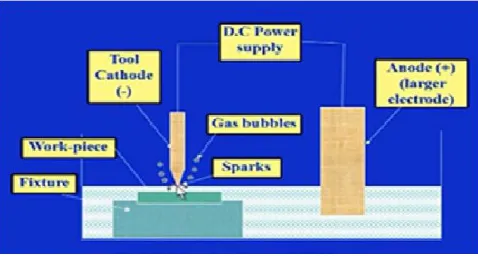
Electrochemical Discharge Machining is a hybrid machining process of EDM and ECM, in which material removal takes place due to material dissolution through electro-chemical action and thermal draining away of material though electrical discharge phenomenon. The electrical and chemical action results in the formation of positive charged hydrogen gas bubbles. The electrical discharge action occur between the tool and work piece due to the break-down of insulating layer of the gas bubbles as the voltage is applied from the power supply to the circuit. This results in removal of material due to melting, vaporization as well as mechanical erosion. It is the process for micro machining and chemical etching of non-conductive materials, which are difficult to process by conventional and other non-conventional techniques.
Laser beam machining is also a non-conventional machining where efficient and precise machining can be done, but the high energy density concentrated on the work piece produces micro-cracks.
[image:1.612.325.564.342.471.2]It forms a recast layer which reduces surface quality. Again Ultrasonic machining is also used to create micro slots and holes on hard brittle material, but the main drawback is that it takes much time because of its low machining speed. Compared with the above mention machining processes ECDM has the advantages over flexibility and simple procedure of machining, with great capability in micro-machining of non-conductive hard brittle materials.
Fig. I.1: Schematic diagram of ECDM
International Journal of Emerging Technology and Advanced Engineering
Website: www.ijetae.com (ISSN 2250-2459, ISO 9001:2008 Certified Journal, Volume 5, Issue 4, April 2015)
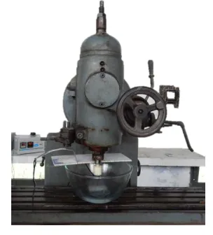
Fig.I.2: ECDM set-up on vertical milling machine
Spark Assisted Chemical Engraving (SACE) was first developed in Japan in 1950 with some applications in diamond cutting workshop. The research paper by Kurafuji and Suda in 1968 was one of the pioneer reports on this new technology, which later on they termed it as electrical discharge drilling. Cook et. al. (1973) gave first characterization of this process. The latest development in this field is the applications of electrochemical discharges to the synthesis of nano-particles. Each of this application is actually hosted in different fields of science and engineering. The discovery of electrochemical discharges was, as is often in science, not a planned observation. Foucault and Fizeau are the discoverers of electrochemical discharges as they were the first to associate these with electrical discharges in 1989. Form then, there are many research program have been done on electrochemical discharge machining process to discover or invent new concept of better way of metal removal process. In 1998 Bhattacharyya et. al. [5] analyses the basic material removal mechanism in the ECDM process for the effective machining of non-conducting ceramic material.
The process was influenced by various process parameters and as a result it showed that at low voltage the MRR is very low but at higher voltage and higher electrolyte concentration the MRR is high. However at higher electrolyte concentration the overcut is greater. Bhattacharyya et. al. [7] in 2004 showed that applied voltage has more significant effects on MRR, ROC, HAZ during ECDM micro-drilling operation than other machining parameters such as electrolyte concentration and inter-electrode gap. Within the boundaries of this investigation, the result obtained for both maximum MRR and minimum ROC and HAZ thickness were confirmed to be valid during the application of a ECDM micro- drilling process. Taking Optical glass and Quartz bars as work piece W.Y. Peng, Y.S. Liao” [22] have worked for material removal rate (MRR) and surface roughness (SR) to identify, with input parameter as applied voltage and
electrolyte obtained using the duty
factor0.53,f=200Hz,MRR= 0.06mm3/min and surface
roughness becomes less and better
transparency(Ra)=3.5μm. Again in 2006 B.Bhattacharya et. al. [23] worked on silicon nitride ceramics taking enter electrode gap in the range of 20-40mm as one of its input parameter. Results showed that material removal rate is to more effective in the combination of 80V and 25% NaOH solution. M.Coteaţă, L.Slătineanu, O.Dodun and Ciofu C (2008) [3] experimentally investigated by trying to achieve small diameters holes by electrochemical discharge machining using an aqueous solution of sodium silicate as working liquid. Identifying an optimized system for mechanical and electrical equipment was one of the targets. By assuring a relative motion between the electrodes, holes (diameter <1 mm) in cutting steel work pieces were obtained. Taking work piece: high speed steel sheet of 1.5 mm thickness; electrolyte: Sodium silicate (chisel steel); electrode tool diameter: 0.5mm – 0.9mm; working voltage: 35V – 45V; capacity: 33µF - 840µF; electrolyte concentration: 1.05g/cm cube – 1.20g/cm cube; working time: 6min; frequency: 80contacts/min. The output parameter for this ECDM drilling experiments was the electrode tool wear. To evaluate output this result, the length of the electrode tools was measured before and after the machining process. It proposes a new solution for drilling by ECDM, in the case of metallic work pieces and emphasized the increase of the electrode tool wear as the electrode tool diameter decreases, and, as the electric capacity, the electric voltage between electrodes and work liquid density increase.
Work piece holding fixture Transformer
+Ve electrode
-Ve electrode
Fixture for inter electrode gap
International Journal of Emerging Technology and Advanced Engineering
Website: www.ijetae.com (ISSN 2250-2459, ISO 9001:2008 Certified Journal, Volume 5, Issue 4, April 2015)
In spite of several studies on ECDM done so far, it is observed that some more study on parametric effects for different electrolytes, mechanism modes and analysis of outcomes is necessary to enhance the existing knowledge base. In this paper some research has been carried out on ECDM process to machine glass taking KOH as electrolyte, and copper & stainless steel as negative and positive electrode respectively, to have a closer overall accuracy on material removal rate followed by parametric analysis using Taguchi’s design of experiment approach and selecting orthogonal array to plan the experiments.
II. EXPERIMENTAL SETUP
In this experiment we had studied the effect of various input parameters for making micro-hole using ECDM process. The experimental setup consists of many system and their sub-systems:
[image:3.612.350.533.123.436.2]The machine: Usually it is a table top fabricated machine or a specialized set-up comprising of all the necessary features. It is a vertical milling machine which is fitted with an insulator at the tool-machine interface to prevent the flow of current onto the overall body of machine.
Fig. II.1: ECDM set-up on vertical milling machine
The pulsed DC power supply: – It is consisting of AC to DC converter and voltage modulator or pulsed modulator. It is a step-down transformer which can module up to 240V. The different parts of the modulator are: The transformer: Comparing with step up transformer, a step down transformer has more number of turns of wire on the primary coil than the secondary coil. This makes the secondary coil to induce smaller voltage. It is known as step down transformer since the output voltage is smaller than the input voltage. If there are half as many turns of wire in the secondary coil, then the output voltage will be half the input voltage.
Fig.II.2: Step-down Transformer
Fig. II.3: Ammeter and voltmeter
Decreasing the voltage does not decrease the power. Step down transformers are used to step down high voltages that is from 11000v to 220v or 110v and from 220v or 110v to 10, 12, 20 or 24 volts etc. Dimmer: The transformer is attached with a dimmer on its top surface. Dimmer plays the primary capability of the transformer. The dimming function on lighting utilizes a transformer to step down the voltage coming in from the mains. For example, if we need to vary a light to 50% of its illumination at 12V, we could rotate the dimmer switch so that 6V are being supplied to the light. This is one of the most common ways that transformers are used in recent days. Voltmeter and ampere-meter: The transformer is having two digital meters. One is ampere meter and the other is voltage meter. The ampere meter shows the reading of current being consumed by the machine and the volt-meter shows the voltage variation of the machining process.
Electrolyte: KOH has been taken as electrolyte for machining. Few properties of the electrolyte are shown below:
KOH is also known as Caustic Potassa, Potassa, Potash lye, and Potassium Hydrate.
[image:3.612.91.243.410.578.2]International Journal of Emerging Technology and Advanced Engineering
Website: www.ijetae.com (ISSN 2250-2459, ISO 9001:2008 Certified Journal, Volume 5, Issue 4, April 2015) It helps in lowering the Freezing Point of water.
It always use for Food grade Quality, not all KOH is the same.
Act as Hazards.
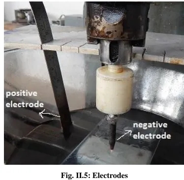
[image:4.612.348.535.209.392.2]Fixture: The fixture is made of many other sub-components like the inter electrode gap control device, borosilicate glass bowl and work piece holding device. The inter electrode gap device is a flat plate having open slots at every 20mm length from the tool position. It allows the positive electrode dipped properly into the electrolyte at desire position. The borosilicate glass bowl act as the container inside of which electrolyte has been kept and work piece holding fixture has been attached inside of it. This gives a strong rigidity to the work piece during machining to prevent from any unnecessary movements. Feed has been given manually to the process at constant rate during machining using feed arrangement attached to the milling machine. Keeping in view the requirements of machining of glass, electric current from DC power supply was applied between the tool and auxiliary electrode.
Fig. II.4: Fixture for positioning electrode
Electrode: There are two electrode used in ECDM. Copper needle is used as cathode or negative electrode and a steel scale is used as anode or positive electrode. ECDM electrodes consists of highly conductive and erosion resistive material such as copper, steel, graphite etc. ECDM electrodes include components made up of brass, copper and copper alloys, graphite, molybdenum, silver, and tungsten. Such material need to have properties that easily allow charge and yet resist the erosion that the ECDM process encourages and stimulates in the non conductor it machines.
The electrodes we have taken here for the experiment are highly conductive in nature and possess less erosion of material during spark generation. Both the electrode has good oxidation at elevated temperature. In the electrode of steel Carbide precipitation can occur in the temperature range 800-1600F.
Fig. II.5: Electrodes
If carbide precipitation does occur it must be removed by heating above 1900F. Copper wire is used to connect both the electrode with the power supply, such that no power is lost. The spark generates at the negative electrode after forming bubbles at its tip. The negative electrode is cylindrical shaped, having point cross section at its tip to make ensure easy slotting or drilling on the material surface.
III. EXPERIMENTAL WORK A. Parameter Selection
[image:4.612.49.291.375.505.2]International Journal of Emerging Technology and Advanced Engineering
[image:5.612.317.569.156.362.2]Website: www.ijetae.com (ISSN 2250-2459, ISO 9001:2008 Certified Journal, Volume 5, Issue 4, April 2015)
Table I
Parameters And Their Values
Parameters Value
Voltage 40V 50V 60V
Concentration of electrolyte
40% 45% 50%
Inter-electrode gap 20mm 40mm 60mm
Ratio of area of electrode
1:20 1:40 1:60
Feed rate 3µm/sec
work-piece material Borosil glass
Auxiliary electrode material
High speed steel
Electrode-material (tool)
Copper electrode
Time 5 minute
Electrolyte temperature
30˚C
Material removal rate is the main response which has to be taken seriously and has to be analyze carefully. It is defined as the total amount of material removed from the work piece per unit time after undergoing machining process. It is calculated as the difference of initial weight before machining to the final weight after machining of the work piece divided by total time taken to remove that amount of material:
MRR (mg/min) =
time machining
weight final weight initial
B. Experimental result
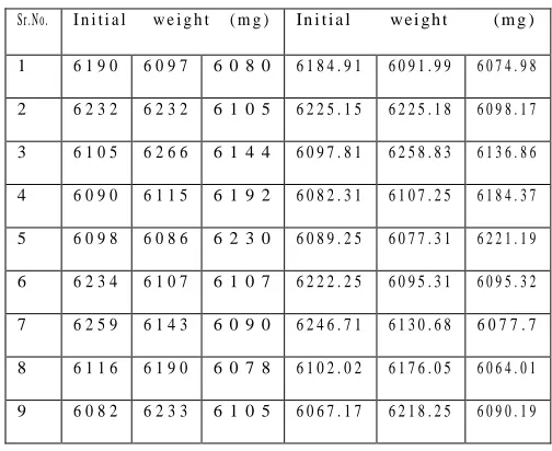
Each experiment was repeated 3 times and the values of material removal rate were used for study purpose. Below tables are showing the values of initial weight and final weight of every glass work piece.
Table II
Initial And Final Weight Of Work Piece
Sr.No. I n i t i a l w e i g h t ( m g ) In i t i a l w e i g h t ( m g )
1 6 1 9 0 6 0 9 7 6 0 8 0 6 1 8 4 . 9 1 6 0 9 1 . 9 9 6 0 7 4 . 9 8
2 6 2 3 2 6 2 3 2 6 1 0 5 6 2 2 5 . 1 5 6 2 2 5 . 1 8 6 0 9 8 . 1 7
3 6 1 0 5 6 2 6 6 6 1 4 4 6 0 9 7 . 8 1 6 2 5 8 . 8 3 6 1 3 6 . 8 6
4 6 0 9 0 6 1 1 5 6 1 9 2 6 0 8 2 . 3 1 6 1 0 7 . 2 5 6 1 8 4 . 3 7
5 6 0 9 8 6 0 8 6 6 2 3 0 6 0 8 9 . 2 5 6 0 7 7 . 3 1 6 2 2 1 . 1 9
6 6 2 3 4 6 1 0 7 6 1 0 7 6 2 2 2 . 2 5 6 0 9 5 . 3 1 6 0 9 5 . 3 2
7 6 2 5 9 6 1 4 3 6 0 9 0 6 2 4 6 . 7 1 6 1 3 0 . 6 8 6 0 7 7 . 7
8 6 1 1 6 6 1 9 0 6 0 7 8 6 1 0 2 . 0 2 6 1 7 6 . 0 5 6 0 6 4 . 0 1
9 6 0 8 2 6 2 3 3 6 1 0 5 6 0 6 7 . 1 7 6 2 1 8 . 2 5 6 0 9 0 . 1 9
[image:5.612.55.284.156.444.2]Experimental design was prepared using L9 orthogonal array based upon taguchi technique. Total 27 experiments were performed. The experimental results are shown in table III.
Table III
S/N Ratio For Process Parameters
Volt age
Conc. of electr olyte
Inter-electrode gap
Ratio of area of electrod e
MRR(mg/min)=
time machining
weight final weight initial
S/N Ratio
R1 R2 R3
40 30% 20mm 1:20 1.018 1.002 1.004 0.068
40 35% 40mm 1:40 1.002 1.364 1.366 2.713
40 40% 60mm 1:60 1.004 1.434 1.428 3.126
50 30% 40mm 1:60 1.37 1.55 1.526 3.738
50 35% 60mm 1:20 1.364 1.738 1.762 4.860
50 40% 20mm 1:40 1.366 2.338 2.336 7.389
60 30% 60mm 1:40 1.438 2.464 2.46 7.821
60 35% 40mm 1:60 1.434 2.79 2.798 8.926
[image:5.612.309.580.436.698.2]International Journal of Emerging Technology and Advanced Engineering
Website: www.ijetae.com (ISSN 2250-2459, ISO 9001:2008 Certified Journal, Volume 5, Issue 4, April 2015)
[image:6.612.325.566.270.396.2] [image:6.612.53.285.546.676.2]L2-L1 is the effect occurs when corresponding parameter value changes from level 1 to level 2. L3-L2 is the effect occurs when the corresponding parameters value changes from level 2 to level 3.
Table IV
Value Of Process Parameters At Different Level
level voltage Conc. Of electrolyte
Inter-electrode gap
Ratio of
area of
electrode S/N
data Raw data
S/N data
Raw data
S/N data
Raw data
S/N data
Raw data L1 1.97 1.27 5.46 2.05 4.78 1.91 3.88 1.67 L2 5.33 1.88 5.29 1.95 5.97 2.06 5.50 1.97 L3 8.72 2.74 5.27 1.88 5.26 1.92 6.65 2.24
L2-L1
3.36 0.61 -0.17
-0.09
1.19 0.15 1.62 0.30
L3-L2
3.39 0.86 -0.02
-0.07
-0.71
-0.13
1.15 0.27
IV. DISCUSSION
The effects of various process variables such as applied voltage, electrolyte concentration, inter electrode gap and ratio of area of electrode on material removal rate have been observed for obtaining the optimal machining characteristics of glass by using electrochemical discharge machining process. The influence of various process parameters and their effect on MRR has been analyzed on KOH as electrolyte.
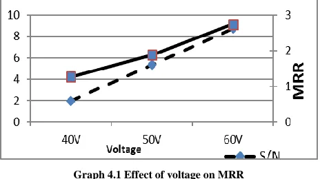
Effect of voltage on MRR:
When the voltage increased, current starts flowing more rapidly along the circuit. This made the electrons gathered in more number near the tip of electrode in lesser time. As a result spark generated continuously and more rapidly, such that material started removing from the work piece.
Graph 4.1 Effect of voltage on MRR
If we increase more voltage, it will generate more sparks per unit time and material will remove more quickly. It is done due to availability of increased energy that ionizes the gaseous layer at the cathode causing sparking.
Effect of concentration of electrolyte on MRR:
On increasing concentration of electrolyte, number of OH ion increased. As a result more hydrogen bubbles formed at the tip of cupper electrode. When this hydrogen bubbles splitted, spark generated. In other words increasing concentration of electrolyte, spark increased and MRR increased. MRR varies with concentration of electrolyte. As we can see in the graph, when concentration was about 30%, the MRR was just about 4. It increases to 11 on increasing the concentration from 30% to 40%. So MRR increases with increasing concentration of electrolyte.
Graph 4.2 Effect of concentration of electrolyte on MRR
The above graph showing the effect of electrolyte concentration on MRR is for KOH electrolyte. It’s highly reactive and with little increase in concentration can produce huge variation in MRR as we can analyses from the graph.
Effect of inter-electrode gap on MRR:
Form the graph 4.3; it can be notice that as the gap between cathode electrode and anode electrode increased beyond a certain value, the MRR starts decreasing. At 20mm, the evolved gases tend to stabilize the sparking process but at higher gap it will destabilize the sparking process and hence MRR decreases.
International Journal of Emerging Technology and Advanced Engineering
Website: www.ijetae.com (ISSN 2250-2459, ISO 9001:2008 Certified Journal, Volume 5, Issue 4, April 2015)
Effect of ratio of area of electrode on MRR:
Graph4.4 effect of ratio of area of electrode on MRR
It can be observed from graph 4.4 that as ratio of area of electrode increases i.e. area of cathode to area of anode ratio; MRR increases up to a certain value and then decreases. MRR is highest for the area ratio as 1:40.
V. ANALYSIS
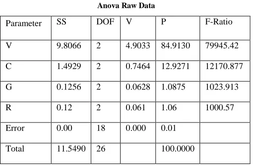
To study the significance of the parameters, ANOVA is performed.
[image:7.612.42.297.503.670.2]The experimental design according to larger the better which preferred to maximize the result, and the ideal target value is infinity. To study the significance of the parameters, ANOVA was performed. It was noted that % contribution of Voltage was highest (83.17) followed by concentration of electrolyte (14.13) and inter electrode gap (2.615).
Table V Anova Raw Data
Parameter SS DOF V P F-Ratio
V 9.8066 2 4.9033 84.9130 79945.42
C 1.4929 2 0.7464 12.9271 12170.877
G 0.1256 2 0.0628 1.0875 1023.913
R 0.12 2 0.061 1.06 1000.57
Error 0.00 18 0.000 0.01
Total 11.5490 26 100.0000
Where, SS-sum of square, DOF-degree of freedom And V-variance. Fcritical=19.00
Table VI name
Parameter SS DOF V P F-Ratio
V 68.43 2 34.22 83.17 977.58
C 11.63 2.00 5.81 14.13 166.11
G 0.07 Pooled
R 2.1515 2 1.0757 2.6150 30.74
Error 0.07 2 0.04 0.09
Total 82.28 8 100.00
Where, SS-sum of square, DOF-degree of freedom and V-variance. Significant at 95% confident level, Fcritical=3.492
VI. CONCLUSION
From this experimental research few points were noticed:
It is easy to obtain micro-hole by proper optimization of process parameters.
Different electrolytes and its temperature can be used for better results.
Drilling time can be reduced by increasing voltage and concentration of electrolytes.
The percentage contribution of voltage is highest, that is 83.17% for S/N data and 84% for raw data followed by concentration of electrolyte, inter-electrode gap and ratio of area of electrode respectively.
In this research paper 120mm hole was obtained at V2
C2 G1 R2. It was noticed that at higher voltage MRR
increases.
REFERENCES
[1] N.S. Mitra, B.Doloi & B.Bhattacharya “Analysis of traveling wire
electrochemical discharge machining of hylam based composite by taguchi method” IMPACT: International Journal of Research in Engineering & Technology (IMPACT: IJRET) ISSN(E): 2321-8843; ISSN(P): 2347-4599 Vol. 2, Issue 2, Feb 2014, 223-236.
[2] Kulkarni, R. Sharan, G.K. Lal “An experimental study of discharge mechanism in electrochemical discharge machining” International Journal of Machine Tools & Manufacture 42 (2002) 1121–1127; Received 19 September 2001; received in revised form 25 April 2002; accepted 29 April 2002.
International Journal of Emerging Technology and Advanced Engineering
Website: www.ijetae.com (ISSN 2250-2459, ISO 9001:2008 Certified Journal, Volume 5, Issue 4, April 2015)
[4] V. Fascio , H.H. Langen , H. Bleuler , Ch. Comninellis “Investigations of the spark assisted chemical engraving” LSR0, EPFL-IPR, CH-1015 Lausanne, Switzerland b Delft University of Technology, Advanced Mechatronics, Mekelweg 2, 2628 CD Delft, The Netherlands c SB-ISP-UGEC, EPFL,CH-1015 Lausanne, Switzerland; Received 19 December 2002; received in revised form 24 January 2003; accepted 24 January 2003.
[5] Bhattacharyya*, B.N. Doloi, S.K. Sorkhel “Experimental investigations into electrochemical discharge machining (ECDM) of non-conductive ceramic materials” Journal of Materials Processing Technology 95 (1999) 145±154; Production Engineering Department, Jadavpur University, Calcutta 700 032, India; Received 24 April 1998.
[6] R. Wiithrich and V. Fascio “Machining of non-conducting materials using electrochemical discharge phenomenon – an overview” International Journal Of machine tools and manufacturing 45 (2005) 1095-1108; received 25 October 2004; accepted 16 November 2004. [7] B.R. Sarkar, B. Doloi & B. Bhattacharyya “Parametric analysis on
electrochemical discharge machining of silicon nitride ceramics” Int J Adv Manuf Techno (2006) 28:873-881 DOI 10.1007/s00170-004-2448-1; Received: 6 July 2004 / Accepted: 18 October 2004 [8] Zhi-Wen Fan & Lih-Wu Hourng “Electrochemical micro-drilling of
deep holes by rotational cathode tools” Int J Adv Manuf Techno (2011) 52:555–563 DOI 10.1007/s00170-010-2744-x; @ Springer-Verlag London Limited 2010; Received: 3 November 2009 /Accepted: 24 May 2010.
[9] Alakesh Manna & Vivek Narang “A study on micro machining of e-glass–fibre–epoxy composite by ECSM process” Int J Adv Manuf Techno (2012) 61:1191–1197 DOI 10.1007/s00170-012-4094-3; @Springer-Verlag London Limited 2012; Received: 6 June 2011 /Accepted: 4 January 2012.
[10] Cheng-kuang Yang, Chih-Ping Cheng, Chao-Chuang Mai and his co-researchers “effect of surface roughness of tool electrode materials in ECDM performance” International Journal Of Machine Tools and Manufacture 50 (2010) 1088-1096. Received in 7 May 2010; Accepted 20August 2010.
[11] Xuan Doan Cao, Bo Hyun Kim, Chong Nam Chu “Micro-structuring of glass with features less than 100µm by electrochemical discharge machining” Precision Engineering 33 (2009) 459-465; Received 18 August 2008; accepted 9 January 2009.
[12] Min Seop Han, Byung-Kwon Min, Sang Jo Lee “Micro-electro discharge cutting of glass using a surface-textured tool” CIRP Journal Of Manufacturing Science Technology 4 (2011) 362-369; 13 July 2011.
[13] M. G. Mostofa, Mohammad Malekian, Simon S. Park & Martin B. G. Jun “Micromechanical machining of soda lime glass” Int J Adv Manuf Techno DOI 10.1007/s00170-012-4554-9; @Springer-Verlag London 2012; Received: 8 July 2012 /Accepted: 2 October 2012. [14] Jana D. Abou Ziki, Tohid Fatanat Didar, Rolf wuthrich
“Micro-texturing channel surfaces on glass with spark assisted chemical engraving” International Journal Of Machine Tools and Manufacture 57 (2012) 66-72; Received: 13 December 2011/Accepted: 25 January 2012.
[15] M.L.Harugade, M.V.Kavade, N.V.Hargude “Effect of electrolyte solution on material removal rate in Electrochemical Discharge Machining” IOSR Journal of Mechanical and Civil Engineering (IOSR-JMCE) ISSN: 2278-1684, PP: 01-08.
[16] Lijo Paul and Somashekhar S. Hiremath “Response Surface Modeling of Micro Holes in Electrochemical Discharge Machining Process” International Conference On DESIGN AND MANUFACTURING, IConDM 2013; Procedia Engineering 64 (2013) 1395 – 1404; Department of Mechanical Engineering Indian Institute of Technology Madras Chennai-600036, India.
[17] M. R. Dhanvijay, B. B. Ahuja “Micromachining of ceramics by Electrochemical Discharge process considering stagnant and electrolyte flow method” 2nd International Conference on Innovations in Automation and Mechatronics Engineering, ICIAME 2014; Procedia Technology 14 ( 2014 ) 165 – 172; Department of Production Engg and Industrial Management, College of Engineering, Pune-411005, Maharashtra, India.
[18] Y.S. Laio, L.C. Wu and W.Y. Peng “A study to improve drilling quality of electrochemical discharge machining (ECDM) process” The Seventeenth CIRP Conference on Electro Physical and Chemical Machining (ISEM); Procedia CIRP 6 ( 2013 ) 609 – 614; Department of Mechanical Engineering, National Taiwan University, No.1, Sec. 4, Roosevelt Rd.,. Taipei, 106, Taiwan, R.O.C. industrial Technology Research Institute, No. 195, Sec. 4, ChunShin Rd., Chutung, Hsinchu, 310, Taiwan, R.o.C.