International Journal of Emerging Technology and Advanced Engineering
Website: www.ijetae.com (ISSN 2250-2459,ISO 9001:2008 Certified Journal, Volume 3, Issue 8, August 2013)
331
Process Parameters Designing and Simulation for the
Non-Isothermal Forging of Ti-6Al-4V Alloy
Sambhunath.P.S
1, Sijo.M.T
21
PG scholar, 2Assistant professor, S.C.M.S. School of Engineering and Technology Abstract- This paper presents the project work done in a
forging industry situated in southern India. This is to find out the relationship between various parameters that affect the non-isothermal forging of Ti-6Al-4V alloy. The process parameters of time and temperature are difficult to measure and control during non-isothermal forging. So this study employs finite element method to establish relationship between the process parameters and deformation behavior. The detailed process models based on experimental conditions, and the flow stress models will be constructed by the localized linear fitting and interpolation method, and they will used in the finite element analysis. Consequently, the simulation of the non-isothermal forging of Ti–6Al–4V will be performed using the ANSYS software.
Keywords- non-isothermal forging, deformation,
simulation, flow stress model,
I. INTRODUCTION
The forging industry situated in the southern India employs the isothermal forging for the forging of Ti alloys, the process is limited by a shorter die life, higher equipment cost and lower production rate. Although having the difficulties of process control and larger variation in product quality, the use of non-isothermal forging provides the advantages of both lower cost of the die and higher production rate. Preliminary studies have been done on the effect of process parameters such as forging speed and contact time on non-isothermal forging. The complex transient phenomena of time and temperature were difficult to correlate in their experiments. At this moment, the numerical simulation method plays a prominent role in clearing up the complex relationship of parameters. A reasonable evaluation of the contact heat-transfer coefficient in simulating non-isothermal forging problems is crucial.
The large and non-uniform plastic deformation and the significant temperature gradient are critical to the process design. The microstructure evolution and flow stress behaviour, as affected by temperature variation during deformation, are also crucial. The flow stress model can obtain reasonable simulating results.
Although the simplest flow stress model, i.e. the power law, is widely employed in metal forming analysis, a significant error would arise should it be applied to a problem such as non-isothermal forging. The flow behavior of Ti–6Al–4V exhibits either softening or strain-hardening under different test temperatures. The different temperatures and cooling rates in as specimen subjected to non-isothermal forging induce a large variation in the microstructure and in the subsequent flow stress. The flow stress should be considered as a function of strain, strain rate, temperature and microstructure in order to be able to obtain a reasonable simulation. Establishing an appropriate flow stress model to simulate the non-isothermal problem is essential.
This paper presents a numerical flow stress model, in which non-isothermal forging is simulated to examine how the process parameters are affected with respect to the non-isothermal deformation behaviour. Non-isothermal deformation mechanisms based on the phase transformation of material and the deformation index are explored to serve as a scientific basis for the non-isothermal forging problem.
II. SCOPE OF WORK
International Journal of Emerging Technology and Advanced Engineering
Website: www.ijetae.com (ISSN 2250-2459,ISO 9001:2008 Certified Journal, Volume 3, Issue 8, August 2013)
332 Therefore, a deformation mechanism for non-isothermal forging was proposed in this paper to explain the deformation behaviour. Hence, the deformation mechanism governing the metal flow of non-isothermal forging can provide guidelines for forging die design and process design.
III. RESEARCH METHODOLOGY
Experimental details
The test conditions were summarized as: a cylindrical Ti–6Al–4V billet with dimensions diameter 14 and Height 21 mm, die temperature 250°C, billet temperature 950°C, upsetting strains 1:3 and 5:6, strain rates 1.0, 0.1, 0.01 l s-1, contact times approximate from zero to 10 s. for different cases. The die and the specimens were heated separately. The billet was soaked at 950°C for 30 min, transferred from a furnace to the die set and then compressed at a specified constant strain rate.
To complete a forging cycle, the schedule is simplified into four operaStion stages as follows:
Stage 1: the billet was transferred from the furnace to the forging machine in 5 s (t1).
Stage 2: the billet was allowed to dwell on the lower die for 2–4 s (t2).
Stage 3: the billet was in contact with both the lower and the upper die under pressure for 0–10 s (t3).
Stage 4: the billet was compressed at constant strain rate (t4).
The temperatures, load, displacement and time were recorded by a data acquisition system. The numerical data to control the motion of ram were also used in the following FEM analysis.
Flow stress model
The flow stress or instantaneous yield strength at which work material starts to plastically deform or flow is mostly influenced by temperature, strain, strain rate, and other factors. Accurate and reliable flow stress models are considered highly necessary to represent work material constitutive behavior under high-speed cutting conditions especially for a (new) material.
The plastic deformation behavior of metals is complex. Many flow stress models or constitutive equations have been proposed from the perspective of the forming industry or from physical metallurgy. Nevertheless, equations in the form of a power law and its variations are the simplest form and are applied extensively in metal forming analysis.
A significant variation of the flow stresses at different temperatures and different strain rates is observed, according to the results of the tests. The power law would be satisfactory if it were employed only to isothermal conditions, but a remarkable error would be induced when using this model to analyze a non-isothermal problem, in which a dramatic temperature gradient exists.
The initial flow stress model was constructed by the power law σ = C ε n . The initial model of the flow stress was constructed by using the Strength Coefficient, Strain hardening exponent (n) and the instantaneous strain value. But the flow stress depends on the other factors like the equilibrium microstructure transformation during non-isothermal forging due to the different cooling rate simultaneously changes the flow stress. So using the finite element analysis method we are constructing a detailed flow stress model as the function of σ =f (ε’, ε, T, M). Then the non-isothermal forging of the Ti–6Al–4V was being simulated using the finite element analysis software. And the relationship between the process parameters and the deformation behavior will be established, then deriving useful design rules.
Not only the process parameters but also the material’s microstructure affects the flow stress. The non-equilibrium microstructure transformation during non-isothermal forging due to the different cooling rate simultaneously changes the flow stress. A previous investigation indicated that the instantaneous flow stress under the continuous cooling situation is lower than that of the isothermal condition. To address this phenomenon a temperature-compensation technique to modify the flow stress in non-isothermal forging. This method was adopted herein with slight modification to account for the volume of the specimen and the operation time
FEM simulation
International Journal of Emerging Technology and Advanced Engineering
Website: www.ijetae.com (ISSN 2250-2459,ISO 9001:2008 Certified Journal, Volume 3, Issue 8, August 2013)
[image:3.612.44.294.147.591.2]333
Table 1
Thermal conduction coefficient of Ti–6Al–4V alloy
Temperature ( °C)
Thermal conduction coefficient (N S-1 °C)
93.0 7.3
205.0 9.1
315.0 10.6
425.0 12.6
540.0 14.6
650.0 17.5
950.0 23.5
[image:3.612.319.571.159.391.2]1100.0 24.5
Table 2
Specific heat of Ti–6Al–4V alloy
Temperature T (oc) Specific heat C (kJ g-1oC)
100 550.0
200 590.0
400 620.0
600 730.0
800 910.0
1000 950.0
1100 1000
Table 3
Density, Poisson’sratio, thermal expansion coefficient, Convection coefficient, emissivity ratio
Density 4.43g cm-3
Poisson’s ratio 0.3
Thermal expansion coefficient 10.5X10⁻⁶ mm mm-1 °C
Convection coefficient 0.02 N S-1 mm-1 °C
emissivity ratio 0.6 N S-1 mm-1 °C4
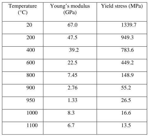
Table 4
Young’s modulus and yield stress of Ti–6Al–4V alloy
Ti-6Al-4V alloy with same size and shape was modeled in the ANSYS software, and the boundary conditions were being applied accordance with the non-isothermal modeling of the Ti-6Al-4V alloy. Significant temperature gradient was observed in non-isothermal forging experiments. Therefore, the properties could not be treated as constant, as in the case of isothermal forging. Temperature-dependent functions for those properties should be considered in the non-isothermal forging analysis.
Table 4 lists the values of Young’s modulus E and the yield stress σ, of the Ti–6Al–4V alloy, Table 1 presents the thermal conductivity coefficient K, and Table 2 lists the specific heat Cp, these properties being treated as
temperature-dependent functions. The density ρ, Poisson’s ratio υ, thermal expansion coefficient a, heat convection coefficient h, and emissivity ratio e of Ti–6Al–4V alloy and H-13 are shown in Table 4 and treated as constant. These data were used in the FEM analysis in an arrayed format. The application of the load and the deformation of the material were simulated using the software and the simulation was being studied.
IV. RESULTS AND DISCUSSION
The microstructure of Ti–6Al–4V alloy is basically a BCC lattice structure (β phase) when the forging temperature is exceeds 950°C. Slight strain-hardening can be found in this temperature region.
Temperature (°C)
Young’s modulus (GPa)
Yield stress (MPa)
20 67.0 1339.7
200 47.5 949.3
400 39.2 783.6
600 22.5 449.2
800 7.45 148.9
900 2.76 55.2
950 1.33 26.5
1000 8.3 16.6
[image:3.612.46.290.159.594.2]International Journal of Emerging Technology and Advanced Engineering
Website: www.ijetae.com (ISSN 2250-2459,ISO 9001:2008 Certified Journal, Volume 3, Issue 8, August 2013)
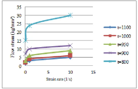
[image:4.612.327.574.135.313.2]334 Conversely, the strain-softening phenomenon is observed when forging temperature is lower than 950°C. In this case, the microstructure is a BCC+HCP lattice structure (α+βdual phase). At a test temperature of 800°C, the softening is dramatic. However, strain-hardening was observed again at a temperature lower than 400°C. According to this experimental observation, the flow stress increases with increasing strain rate, but the temperature is a more sensitive parameter than strain rate within the range of 200°C<1100°C and 0.1 l/S<10.0 l/ s. Around 950°C, the slope change of temperature versus stress is notable, which can be explained as the alteration of the deformation mechanism, which is transformed from a single phase (BCC) slip system to a dual phases (BCC+HCP) slip system. In the non-isothermal forging of Ti–6Al– 4V, these diverse phenomena mentioned above may occur simultaneously because of the large variation of temperature distribution and cooling rates.
Figure 1. Flow stress of Ti–6Al–4V alloy fitted with the power lawfor a specified strain and different test temperatures.
The deformation profiles for isothermal and non-isothermal compression are quite different. From the investigation of the microstructure of Ti–6Al–4V and the flow stress behaviour, two deformation mechanisms are presented in this work to explain the formation of the profiles of the forged billet
0 20 40 60 80 100 120
0 500 1000
F
lo
w
st
re
ss (k
g
/mm
2)
Temperature (oc)
strain=.6 strain rate=.1
strain=.2 strain rate =.1
strain=.2 strain rate=1
[image:4.612.53.288.355.508.2]strain=.6 strain rate=1
Figure 2. Flow stress with respect to the test temperature
Deformation mechanism based on microstructure evolution
Phase transformation in the solid state, according to the driving force, can be classified into two types: these are diffusion-controlled phase transformation and non-controlled phase transformation. In diffusion-controlled phase transformation, transformation time is required. When a material is cooling from a high temperature, the phase will change according to the equilibrium of free energy, ∆G=∆H-T∆S. The phase transformation will occur if ∆G<0, where ∆G is composed of the bulk free energy, the surface free energy, the chemical free energy, the strain free energy… etc. There are large differences between equilibrium phase transformation and non-equilibrium phase transformation. In isothermal forging, the phase of the material could be considered in an equilibrium situation and the phase variation is relatively small, because of the relative uniformity of temperature.
International Journal of Emerging Technology and Advanced Engineering
Website: www.ijetae.com (ISSN 2250-2459,ISO 9001:2008 Certified Journal, Volume 3, Issue 8, August 2013)
335 There are 48 slip systems in Body-Centered Cubic and12 slip systems in Hexagonal Closed-Packed. In non-isothermal forging, the change of thermal derived free energy makes the lattice structure change from BCC to HCP, hence the dominated plastic slip systems will govern the non-uniform deformation pattern. It is complex to study the change of slip system from microscopic observation, but from compression tests and the investigation of flow stress behaviour, the transfer of the dominant slip system can be identified easily
Temperature sensitivity factor
A temperature sensitivity factor Sσ,T can be defined as:
Sσ,T = (σ non/Tnon) = (Tave/ σave)
Where σ non =( σ h- σl )/ σ ave is the non-uniformity of
stress, and Tnon=(Th-Tl)/Tave is the non-uniformity of
temperature. (∆s)/( ∆T) is the slope in the stress– temperature diagram. Suffix ‘h’ means stress or
temperature at higher level, ‘l’ means stress or temperature
at lower level, and ‘ave’ means the average of stress or temperature.
0 2 4 6 8 10 12 14 16 18 20
200 400 600 800 1000 1200
St
res
s
sen
si
ti
v
it
y
Temperature oc
ti-6Al-4Vi
[image:5.612.326.559.280.446.2]ti-6Al-4Vi
Figure 3. The sensitivity S σ,T vs. temperature.
In diagram of the temperature sensitivity on the flow stress, S σ,T versus temperature, there exists a peak which
appears at around 925°C. This can be defined as the transformation of the plastic deformation mechanism (change from a single slip system (BCC) to a dual slip system (BCC+HCP)).
Deformation mechanism based on the deformation index
The microstructure evolution gives a base from which to understand the effect of the micro-deformation mechanism on the non-isothermal deformation pattern, In a single lattice structure, the flow stress is affected by temperature, the response of flow stress to temperature differing from phase to phase. The deformation index is used from the viewpoint of the stress fluctuation in the work piece to explain the deformation mechanism. If the value of stress fluctuation ∆ σ is the same but the average stress σ ave
[image:5.612.52.289.419.616.2]differs, a lower average stress with stress fluctuation ∆ σ behaves as a more severe non-uniform deformation.
Figure 4. Concept of non-uniformity of stress
This mechanism for non-isothermal deformation is explained as depicted in Fig. 9. Due to the different thermal boundary conditions in the forging stages, different cooling rates and a maximum difference of temperature exist. The slopes of flow stress with respect to temperature vary with different temperature, From the non-uniformity of stress σ
non=( σh- σl)/ σ ave and considering a situation as shown the
relationship of (∆σ: σ ave,l)>( ∆ σ/ σ ave,h) exists whilst the
slope and ∆s remain constant. This finding suggests that the stress non-uniformity at a lower stress level is larger than that at a higher stress level. A larger slope of the stress– temperature curve and a larger difference of σave, imply a
International Journal of Emerging Technology and Advanced Engineering
Website: www.ijetae.com (ISSN 2250-2459,ISO 9001:2008 Certified Journal, Volume 3, Issue 8, August 2013)
336 A material with these characteristics of flow stress undergoes non-isothermal forging and has a large deformation index Dindex so that in the work piece,
[image:6.612.43.297.205.487.2]non-uniform plastic deformation is significant.
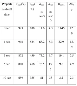
Table 5.
The properties of process parameters before compression
Properti
es/dwell
time
Tmax(oc) Tmin(
oc)
σmax
(N
mm-2)
σmin
(N
mm
-2)
Dindex ∆Sσ,
T
0 sec 923 838 11.6 4.3 3.645 12.
0
1 sec 916 524 68.2 5.3 32.9 13.
9
3 sec 872 459 73.2 9.7 19.1 7.5
5 sec 810 418 76.5 15.
7
9.6 4.9
10 sec 659 355 81 33 3.2 2.3
In Equation σ max is the maximum stress, σ min is the
minimum stress, and S is the slenderness ratio of billet. From the FEM analysis and the observation of flow stress curve, Table shows the values of ∆Sσ,T and Dindex under
some non-isothermal conditions, and indicates that a larger value of ∆Sσ,T will produce a severe ‘local’ non-uniform
deformation, whilst a larger value of Dindex will produce a
severe ‘global’ non-uniform deformation: this is verified in Figs. 10–13. In the case of a dwell time of 1 s, both ∆Sσ,T
and Dindex reach their maximum value, the deformation
Pattern being the most non-uniform. In the case of zero dwell time, the deformation index Dindex is small, but the
difference of temperature sensitivity ∆Sσ,Tis large. Hence,
from the simulation result, non-uniform deformation occurs in die corner at first, and finally forms the folding lap. In the case of a dwell time of 10 s, both Dindex and ∆Sσ,T are
small, so that a relatively uniform deformation pattern is exhibited and no folding lap occurs.
The isothermal case (where heat exchange with the environment is allowed) and the ideal isothermal case (no heat exchange occurs) are also presented in this table for comparison. Both ∆Sσ,T and Dindex in these two cases are
small (close to zero), hence the deformation pattern in isothermal forging is relatively uniform. If the friction force was neglected, the deformation in isothermal forging would be homogenous deformation.
The relationship between these two deformation mechanisms is straightforward. The different phase structure provides the different properties of plastic deformation. Hence, the flow stress of different phases with respect to temperature varies. The ‘Sσ,T’ indicates that the
value of the flow stress depends upon the temperature. A larger Sσ,T means a larger stress variation upon change of
temperature: this is an intrinsic property of the material. On the other hand, the deformation index Dindex indicates the
effect of the process parameters and the geometry of billet on the deformation. This mechanism relates to the forging condition. It is clear that the control of temperature in the non-isothermal forging process is important. The transfer time, the contact time, and the dwell time, must be well controlled to obtain a more uniform deformation.
The temperature sensitivity Sσ,T and the deformation
index Dindex are generalized characteristics in the material
behaviour and the forging problem. Each material has a value of Sσ,T, exhibiting a peak in different test
temperatures of with different magnitudes. From the magnitude of Sσ,T, the plastic behaviour of materials can be
compared. On the other hand, the process characteristic is reflected by the deformation index, Dindex. If a process has a
large magnitude of Dindex, a significant non-uniform
deformation pattern will be observed. In isothermal forging, both the difference of Sσ,T, and the value of Dindex
are small due to the smaller temperature variation, therefore the deformation pattern is relatively uniform. Conversely, the difference of Sσ,T, and the value of Dindex vary according
to the different non-isothermal forging conditions, hence, a more non-uniform deformation pattern results.
FEM simulation and characteristics of process parameters
International Journal of Emerging Technology and Advanced Engineering
Website: www.ijetae.com (ISSN 2250-2459,ISO 9001:2008 Certified Journal, Volume 3, Issue 8, August 2013)
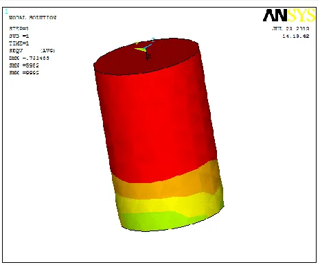
337 Apart from that, the simulation results in Figure 5 correlate well with experimental results. The flow stress of Ti–6Al–4V was affected by a balanced temperature. Consequently, adhering to the principle of non-uniform deformation mechanism, the coincidence of the results was evident.
[image:7.612.50.285.294.483.2]The effect of the process parameters on the deformation can then be clarified as both strain rate and contact time being correlatively affective during deformation, but contact time being dominant. Simulations with reasonable flow stress and process procedure models are the keys to improving the experimental work, particularly for the non-isothermal problem
Figure 5. Deformation of the work piece at time 10 sec
Figure 6. Stress distribution of the work piece at 10 sec
Process design and tool design for non-isothermal forging: The non-isothermal deformation mechanism and the contact time dominate the deformation pattern. The selection of the simulation tool, the design rules of process parameter and the die geometry for non-isothermal forging must be based on this knowledge to obtain a consistent solution.
A successful process simulation is the key to the non-isothermal forging problem. The transfer time, the contact and dwell times, and the compression rate of billet must be controlled within a reasonable tolerance to maintain a higher billet temperature and a more uniform temperature distribution. This task of operation time control is based on a reasonable simulation, because transient phenomenon in the practice of non-isothermal forging are too complex to measure.
The non-isothermal deformation mechanism should be also taken into account in the resign of the billet preform and the geometry of the die in non-isothermal condition. The microstructure evaluation, the metal flow of work-piece, the unstable plastic flow of work-work-piece, the die filling capability, the dead metal zone of specimen, and even the process defects are influenced by the temperature distribution and the non-uniformity of stress. There are some design guidelines that can be drawn in respect of process parameters and die geometry
For the design of process parameters:
1. To obtain a symmetrical deformation pattern, the equality of the contact time of the billet with both the upper and the lower dies must maintain.
2. The values of ∆Sσ,T and Dindex must be reduced to
obtain a more uniform deformation pattern, this being achieved by coating thermally resistant material onto billet to minimize the temperature drop, and by placing a thermally resistant material into the interface to reduce the billet’s temperature gradient, and shorten the contact and dwell times.
3. The contact area and the number of contact points should be reduced to reduce the die-chilling Effect. 4. The operation time to avoid variation of the
deformation pattern should be controlled strictly either by employing qualified workers or by an automatic material transfer system.
For the design of die geometry:
1. The metal flow near the contact portion was restricted due to the larger ∆Sσ,T and Dindex in non-isothermal
[image:7.612.51.284.509.703.2]International Journal of Emerging Technology and Advanced Engineering
Website: www.ijetae.com (ISSN 2250-2459,ISO 9001:2008 Certified Journal, Volume 3, Issue 8, August 2013)
338 2.The slenderness ratio of preform should be smaller in
non-isothermal forging to lessen the non-uniform deformation.
3.The shape of die cavity in non-isothermal forging must be simpler than that in isothermal forging, because a large dead metal zone exists in non-isothermal forging.
The behaviour of metal flow is difficult to describe quantitatively, thus the detail design of process parameters and die geometry should be evaluated through reasonable process simulation. The finite element method with the localized linear fitting and interpolation method for flow stress, as well as the concept of temperature sensitivity and deformation index, have been proven to be effective analysis methodology for the non-isothermal forging.
V. CONCLUSION
1.The significant microstructure variation in non-isothermal forging due to the die-chilling effect is the intrinsic factor in respect of the deformation profile. Therefore, non-isothermal deformation mechanisms accounted for the deformation patterns of Ti–6Al–4V in non-isothermal forging.
2.The difference of temperature sensitivity ∆Sσ,Tand the
deformation index Dindex are useful criteria to predict
the deformation pattern in non-isothermal forging. Some useful design rules for process parameters and die geometry can be derived based on the concept of reducing the magnitude of ∆Sσ,Tand Dindex.
3. To gain a uniform quality both in microstructure and product geometry, the operation time in each stages must be controlled strictly. Therefore, an automated operation system is needed to fulfill this requirement. 4. Knowledge of non-isothermal deformation characteristics together with a suitable simulation method is the key to solving the non-isothermal forging problem.
REFERENCES
[1] Experimental and theoretical analysis of deformation and
microstructural evolution in the hot-die forging of titanium alloy aerofoil sections Z.M. Hu a,*, J.W. Brooks b, T.A. Dean a a IRC for Materials of High Performance:School of Manufacturing and Mechanical Engineering, The Uni6ersity of Birmingham
[2] Process design based on the deformation mechanism for the
non-isothermal forging of Ti–6Al–4V alloy Rong Shean Lee *, Huan Chang Lin Department of Mechanical Engineering, National Cheng Kung Uni6ersity, Tainan, Taiwan, ROC
[3] W.S. Lee, C.F. Lin, High-temperature deformation behavior of
Ti6Al4V alloy evaluated by high strain-rate compression tests, J. Mater. Process. Technol. 75 (1998) 127–136.
[4] H. Fujii, H. Suzuki, Y. Nakamura, Transformation characteristics of