International Journal of Emerging Technology and Advanced Engineering
Website: www.ijetae.com (ISSN 2250-2459,ISO 9001:2008 Certified Journal, Volume 5, Issue 6, June 2015)
323
Modal Analysis and Harmonic Response Analysis of a
Crankshaft
Dr. C. M. Ramesha
1, Abhijith K G
2, Abhinav Singh
3, Abhishek Raj
4, Chetan S Naik
51Associate Professor, Dept. of Mechanical Engg, M.S.R.I.T, Bangalore, India. 2,3,4,5Undergraduate Students, Dept of Mechanical Engg, M.S.R.I.T Bangalore, India
Abstract— Modal analysis is a very important technique which helps in determining the natural frequencies as well as mode shapes of a structure. In this study modal analysis of a single cylinder engine crankshaft is carried out in ANSYS Workbench 14.0 and first twelve modes of vibration are extracted for free-free as well as constrained boundary conditions. The mode shapes are observed which provide a comprehensive picture of deformations occurring. Harmonic response was also studied by subjecting the component to an exciting frequency range of 0 – 5000 Hz . The results are provided in a graphical format.
Keywords— Modal Analysis, ANSYS Workbench, Harmonic response, crankshaft
I. INTRODUCTION
Modal analysis is a technique to study the dynamic characteristics of a structure under vibrational excitation. Natural frequencies, mode shapes and mode vectors of a structure can be determined using modal analysis. Modal analysis allows the design to avoid resonant vibrations or to vibrate at a specified frequency and gives engineers an idea of how the design will respond to different types of dynamic loads. The crankshaft of an engine is one such structure whose dynamic characteristics can be better studied by modal analysis.
The objective of this study is to determine the natural frequencies of a single cylinder engine crankshaft, study the mode shapes and subject the crankshaft to a harmonic loading varying in frequency from 0 – 5000 Hz and study its response in terms of displacement and stress. The dynamic load analysis has been carried out in MATLAB and further analysis i.e, modal and harmonic response has been carried out in Finite Element package ANSYS Workbench 14.0. Modal analysis proved to be very helpful in geometry optimization of the crankshaft which was one of the aims of the complete study. The benefits of using ANSYS were that mode shapes could be accurately visualized and simulated. So the deformations occurring in the crankshaft could be located with precision. A graphical variation of number of modes vs the frequency can also be obtained from ANSYS Workbench.
Natural frequencies are extracted both for free-free as well as boundary conditions applied. The geometry modelling of the crankshaft was done in AUTODESK INVENTOR 2015.
II. LITERATURE REVIEW
Extensive literature survey was done on the procedure of modal analysis and the past studies done. Finite Element Method seems to be a better and reliable option in analyzing modal characteristics as its quick and very informative
Mr.S.J.Patil [1] in their paper Modal analysis of compressor crankshaft presents the analytical and FE modal analysis of a crankshaft. For analytical calculations, the crankshaft is considered as two rotor system to calculate the natural frequency.
Quan ke Feng [2] in their study Simple Modeling and Modal Analysis of Reciprocating Compressor Crankshaft System proposed to simplify the analysis of the three-dimension vibrations of reciprocating compressor crankshaft system under working conditions, a spatial finite element model based on 3-node Timoshenko beam. Jian Meng [3] studied the stress as well as modal analysis of a 4-cylinder diesel engine by analysis a single crankthrow.
Momin Muhammad Zia Muhammad Idris et al [4] discussed the optimization of crankshaft using strength analysis.The results of modal analysis of modified design is also done to investigate possibility of resonance.
Farzin H. Montazersadgh and Ali Fatemi [5] presented that a dynamic simulation was conducted on a crankshaft from a single cylinder four stroke engine. They have also studied optimization of the crankshaft.
Amit Solanki et.al [6] explained that the performance of any automobile largely depends on its size and working in dynamic conditions.
International Journal of Emerging Technology and Advanced Engineering
Website: www.ijetae.com (ISSN 2250-2459,ISO 9001:2008 Certified Journal, Volume 5, Issue 6, June 2015)
324
III. MODAL ANALYSIS
FIG 1- SOLID MODEL IN AUTODESK INVENTOR
[image:2.595.305.561.133.239.2]Modal analysis was carried out on forged steel material whose properties are as follows :
Table I –
material properties of forged steel
Young’s modulus 2.21e11 Pa
Poisson’s ratio 0.3
Bulk modulus 1.84e11 Pa
Shear modulus 8.50e10 Pa Yield strength 6.25e08 Pa Ultimate strength 8.27e08 Pa
Density 7833 Kg/m3
CONDITION 1 – FREE-FREE
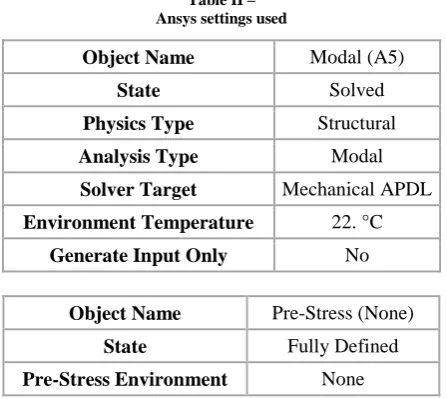
In this analysis no boundary constraints were applied on the model and modes are extracted. The solver used is Block Lanczos and settings used in ANSYS are as follows
Table II – Ansys settings used
Object Name Modal (A5)
State Solved
Physics Type Structural
Analysis Type Modal
Solver Target Mechanical APDL
Environment Temperature 22. °C
Generate Input Only No
Object Name Pre-Stress (None)
State Fully Defined
Pre-Stress Environment None
CONDITION 2 – WITH BOUNDARY CONDITIONS
In this analysis the crankshaft was subjected to boundary conditions. Ball bearing constraint was applied for 180 degrees as surface contact on one side and journal bearing constraint was applied for 180 degrees on the other side as a line contact.
Fig 2 – boundary conditions applied
First twelve modes of vibration were extracted in this case as well.
IV. HARMONIC RESPONSE
A harmonic, or frequency-response, analysis considers loading at one frequency only. Loads may be out-of-phase with one another, but the excitation is at a known frequency.
In a harmonic analysis, Young’s Modulus, Poisson’s Ratio, and Mass Density are required input. All other material properties can be specified but are not used in a harmonic analysis
Because of the fact that modal coordinates are used, a harmonic solution using the Mode Superposition method will automatically perform a modal analysis first. Simulation will automatically determine the number of modes n necessary for an accurate solution
Although a free vibration analysis is performed first, the harmonic analysis portion is very quick and efficient. Hence, the Mode Superposition method is usually much faster overall than the Full method. Since a free vibration analysis is performed, Simulation will know what the natural frequencies of the structure are. In a harmonic analysis, the peak response will correspond with the natural frequencies of the structure
.
The analysis settings used for harmonic response are as followsTable III
Ansys settings for harmonic response
State Fully Defined
Range Minimum 0. Hz
Range Maximum
5000. Hz
Solution Intervals
100
Solution Method Mode Superposition
Cluster Results No
Modal Frequency
Range
[image:2.595.49.291.151.279.2] [image:2.595.42.287.331.439.2] [image:2.595.53.277.503.702.2]International Journal of Emerging Technology and Advanced Engineering
Website: www.ijetae.com (ISSN 2250-2459,ISO 9001:2008 Certified Journal, Volume 5, Issue 6, June 2015)
325 Frequency and phase response was analyzed for the crankpin portion of the crankshaft. The load magnitude considered was 20.894 MPa as this was the maximum load obtained from dynamic analysis.
V. RESULTS AND DISCUSSIONS
[image:3.595.313.585.137.680.2]Natural frequencies for condition 1 free-free are given as follows
Table IV
frequencies and corresponding modes
Fig.3- variation of number of modes vs frequency. X-axis contains number of modes and Y-axis contains frequency
In natural free-frequency the crankshaft should not be vibrating but some period of time vibrations are occurred because self-weight of the crankshaft. Of the 12 mode shapes extracted, some of the mode shapes are shown here.
[image:3.595.315.575.153.257.2]Mode shapes
Fig.4- Mode 1(rigid body displacement)
Fig.5 - Mode 2(rigid body displacement)
Fig.6 – mode 7(bending mode)
Fig.7 – mode 8(combined bending and torsion)
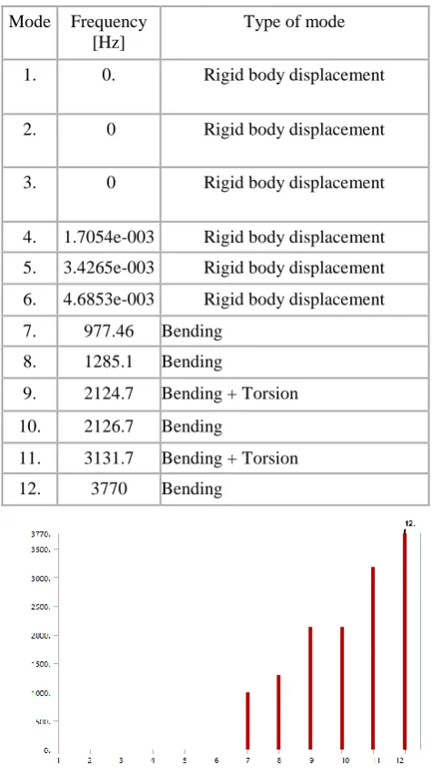
Natural Frequencies for condition 2 –with boundary conditions
Mode Frequency
[Hz]
Type of mode
1. 0. Rigid body displacement
2. 0 Rigid body displacement
3. 0 Rigid body displacement
4. 1.7054e-003 Rigid body displacement
5. 3.4265e-003 Rigid body displacement
6. 4.6853e-003 Rigid body displacement
7. 977.46 Bending
8. 1285.1 Bending
9. 2124.7 Bending + Torsion
10. 2126.7 Bending
11. 3131.7 Bending + Torsion
[image:3.595.44.282.260.686.2]International Journal of Emerging Technology and Advanced Engineering
Website: www.ijetae.com (ISSN 2250-2459,ISO 9001:2008 Certified Journal, Volume 5, Issue 6, June 2015)
326 TABLE V
FREQUENCIES AND MODES
Mode Frequency [Hz] Type of Mode
1.
908.55
Bending
2.
1023.
Bending
3.
1787.9
Bending
4.
3660.
Bending + Torsion
5.
3799.3
Bending + Torsion
6.
4143.9
Bending
7.
4692.
Bending
8.
5026.3
Bending + Torsion
9.
5237.8
Bending + Torsion
10.
5368.7
Bending + Torsion
11.
5623.7
Bending
12.
5974.7
Bending
FIG 8– VARIATION OF MODES VS FREQUENCY. X-AXIS CONTAINS NUMBER OF MODES AND Y-AXIS CONTAINS FREQUENCIES OF MODES
MODE SHAPES
Fig.9 - Mode 1 (bending mode)
Fig.10 – Mode 2 (bending mode)
Fig.11 – Mode 4 (combined bending and torsion)
Fig.12 – Mode 5 (combined Bending and Torsion)
Results of Harmonic Response Analysis
International Journal of Emerging Technology and Advanced Engineering
Website: www.ijetae.com (ISSN 2250-2459,ISO 9001:2008 Certified Journal, Volume 5, Issue 6, June 2015)
327 Fig.14 - variation of stress amplitude with different exciting
frequencies
As can be seen from the graphs the peaks correspond to the resonance conditions. But the engine operating frequencies are well below the resonance conditions, hence resonance conditions are easily avoided.
Fig.14 – phase response for the forged steel crankshaft for one complete engine cycle of 720 degrees
VI. CONCLUSION
Modal analysis was carried out for a single cylinder engine crankshaft.
The natural frequencies of two conditions were found out and analyzed. The variation of number of modes vs frequency has been plotted graphically. Mode shapes are observed for careful examination of deformation. The type of mode with the corresponding frequency has been tabulated. These characteristics prove to be very helpful in the design of the crankshaft for dynamic conditions.
Harmonic response of the crankshaft for the excitation in the range of 0-5000Hz has been studied. Variation of stress and displacement amplitude (frequency response) with respect to frequency has been graphically plotted. Phase response of the crankshaft has also been studied. These characteristics help in better understanding of vibration response of a component subjected to dynamic loading.
REFERENCES
[1] Mr.S.J Patil “ Modal analysis of compressor crankshaft”, International
Journal of Scientific Reasearch, vol-2, Issue:7, ISSN: 2277-8179, Pages:
155-158, July-2013
[2] Yu, Binyan; Yu, Xiaoling; and Feng, Quanke, "Simple Modeling and Modal Analysis of Reciprocating Compressor Crankshaft System"
(2010). International Compressor Engineering Conference. Paper 1982.
http://docs.lib.purdue.edu/icec/1982
[3] Finite Element Analysis of 4-Cylinder Diesel
Crankshaft , Jian Meng, Yongqi Liu, Ruixiang Liu, I.J. Image, Graphics and Signal Processing, 2011, 5, 22-29 Published Online August 2011 in MECS (http://www.mecs-press.org/)
[4] Momin Muhammad Zia Muhammad Idris “ Optimization of crankshaft
using strength analysis”, International Journal of Engineering Reasearch
and applications, Vol-3, Issue-3, ISSN:2248-9622, Pages: 252-258, MayJun-2013
[5] Dynamic load and stress analysis of crankshaft, Farzin H. Montazersadgh and Ali Fatemi, SAE international paper, 2007-01-0258
[6] Amit Solanki, Ketan Tamboli, M.J.Zinjuwadia„ Crankshaft Design and Optimization- A Review‟ National Conference on Recent Trends in Engineering & Technology