© 2016, IRJET | Impact Factor value: 4.45 | ISO 9001:2008 Certified Journal | Page 483
Comparision of different control techniques for three level DC-DC
boost converter
1
Lokesh Bulla
2V Nattarasu
1M.Tech in Industrial Electronics, SJCE, Mysuru 2 Associate Professor, Dept. of ECE, SJCE, Mysuru
1[email protected] 2[email protected]
Abstract
— This paper present the Design and simulation of Multilevel DC/DC Boost converter operating in continuous conduction mode using Proportional Integral Derivative (PID) controller. The performance and properties of Proportional Integral Derivative (PID) controller is compared with pulse width modulation based sliding mode controller (SMC) and Proportional Integral (PI) controller. Simulation results show that the PID control scheme provides good voltage regulation and is suitable for multilevel boost DC-to-DC conversion purposes. The derived SMC controller/converter system is suitable for any changes on line voltage and parameters at input keeping load as a constant.Keywords: Multilevel DC/DC Boost converter, Proportional Integral Derivative (PID) controller, sliding mode controller (SMC), Proportional Integral (PI) controller.
I. INTRODUCTION
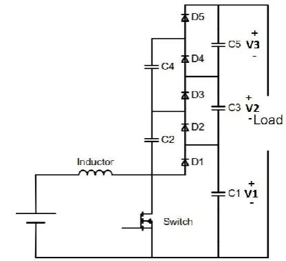
The power converter has become an essential component in the design of clean energy systems. It is used in photovoltaic systems, wind energy systems, hybrid vehicles, portable devices and power supply. Multilevel converter is a good candidate for the medium and high power applications. It is one of the most used converter topologies because of their many advantages, such as their low harmonic distortion, low voltage stress on power switches, high output voltage gain and high efficiency [1]-[2]. Recently, Three level Boost DC-DC Converter (TLBC) was proposed (Figure 1)[3]-[4]. Comparing with the conventional boost DC-DC converter, TLBC presents several advantages such as self voltage balancing and without using an extreme duty ratio its gives high voltage gain. TLBC is switched nonlinear system. These controllers are designed the usage of conventional linear manage strategies where in the small sign version is derived from the linearization round a nominal factor of area nation average model. A suitable controller for , three level boost
[image:1.595.324.532.410.599.2]converter have to deal with its intrinsic non linear and input voltage and load changes, making sure that stability at any operating condition. Because of its Switched nature, three level boost converter can be considered as a variable structure system. Therefore it can be managed the usage of well-known techniques of sliding mode controller (SMC) [4]-[5], PID control and PI control. SMC has been widely used and correctly carried out in DC-DC converters. The principle advantages of SMC on conventional manipulate are robustness, accurate dynamic reaction, simple implementation and low implementation cost.
Figure 1: The Electrical Diagram Of Three Level Boost Converter
II. MODELING OF THE CONVERTERS
© 2016, IRJET | Impact Factor value: 4.45 | ISO 9001:2008 Certified Journal | Page 484 Figure 2: The Reduced Order Model When the Switch is closed
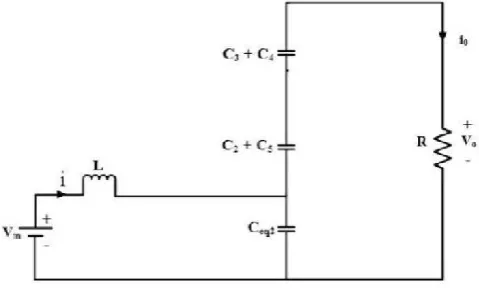
Figure 3: The reduced order model when the switch is open
It is assumed that TLBC operates in continuous conduction mode (CCM) and all components to be ideal. By using basic principle and equating C = C1 = C2 = C3 = C4 = C5,
the equivalent capacitor becomes , Ceq2= C1,
,
and further to this the voltage across every capacitor at the output might be taken into consideration because the circuit output of voltage divided by the number of
capacitors at the output i.e . In terms of equation,
V1 = V2= V3= V/3 ……… (1)
the circuit shown in Figure1 and equation (1), the dynamics for the inductor current and output voltage can be written as,
When Switch is closed
………….. (2)
When Switch is Open
……….. (3)
From above Equation can be written in combine form that is valid for switch ON and switch OFF state
……….. (4)
Where the average input denoted by Uav is actually the duty cycle of the switch. Let us consider Ceq1 Uav + (1- Uav) Ceq2 as C(t)the time varying parameter ((Eq(4))
…………(5)
Using the inductor current and output voltage as state variables, above Equation can be written in state space form as expressed below
III. CONTROL TECHNIQUES USED IN THREE LEVEL DC-DC BOOST CONVERTER
© 2016, IRJET | Impact Factor value: 4.45 | ISO 9001:2008 Certified Journal | Page 485 sliding mode control (SMC), PI control, PID control and P
control. In this paper three level DC-DC boost converter we compare the properties of sliding mode control, PI control and PID control
A. Proportional Integral (PI) controller:
P-I controller is particularly used to eliminate the steady state error came from P control. However, in terms of the speed of the output and overall stability of the system, it has a negative effect. This controller is widely used in area where speed of the system is not a problem. Since PI controller has no ability to predict the further errors of the system it cannot reduce the rise time and eliminate the oscillations.
B. Proportional Integral Derivative (PID) controller:
Three control techniques namely proportional, integral and derivative are combined to get proportional integral derivative. PID controller has the best control dynamics including zero steady state error, short rise time and higher stability. The necessity of using of a derivative gain component in addition to the PI controller is to remove the overshoot. One of the main advantages of the PID controller is, it can be used with higher order system process including more than single energy storage. The constant used in PID are Kp, Ki and Kd.
C. Sliding Mode Control:
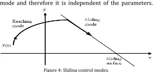
The sliding mode control provides a method for designing a system so that if any variations in parameter and external disturbances the system is insensitive. The technique consists of two modes (Figure. 4). Namely Reaching mode and sliding mode .The reaching mode in which the trajectory slide towards the switching surface from initial point. The other is the sliding mode in which the trajectory slides along the switching surface. And switching surface equation is defined during this sliding
[image:3.595.307.560.97.217.2]mode and therefore it is independent of the parameters.
Figure 4: Sliding control modes.
The control objective in power converter is to force Vo to track a given constant reference voltage Vref
The design of SM control is done in two stages: 1) choose a sliding surface that provides asymptotically the desired dynamic in sliding regime and then 2) the control law is designed to achieve this surface [7]-[8]. The first step in the design of SM control is describing the system by state space equations.
Where
And the matrixes A, B and D are given by
After getting the space state matrix, the next step is to design controller. For switched converters it is convenient to have a control law adopts a switching function such as
© 2016, IRJET | Impact Factor value: 4.45 | ISO 9001:2008 Certified Journal | Page 486 Where, 𝛼1, 𝛼2 and 𝛼3 are control parameter of sliding
mode control and termed as sliding coefficients. A sliding surface can be obtained by forcing, S = 0. Finally, the mapping of the equivalent control function onto the duty ratio control d.
Gives the following relationship for the control signal Vc and ramp signal 𝑉𝑟am𝑝, where
IV. SIMULATION RESULTS
The simulations were performed with the following parameter
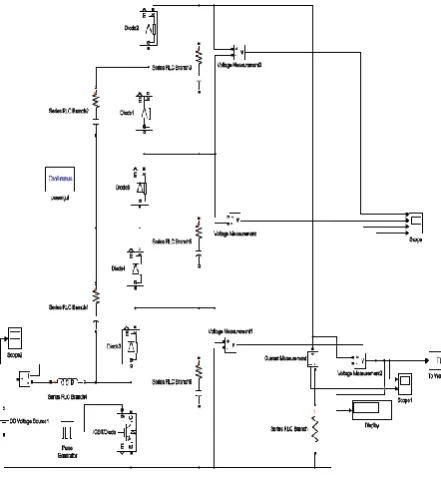
[image:4.595.308.560.179.309.2]Values: L = 180 µH, C = 150 μF. The reference current iref is calculated from equation (Eq. (6)).
Figure 5: Simulink Block of TLBC
A. Simulink Block and Waveforms of TLBC without controller
The waveform of three level boost converter without controller is shown below. Without controller TLBC has more overshoot.
Figure 6: TLBC Output Voltage and Current Wave Forms
B. Simulink Block and Waveforms of TLBC with PI controller
[image:4.595.306.568.466.614.2]The waveform of three level boost converter with PI controller is shown below. TLBC with PI controller has less overshoot compare to without controller. PI control is design with PI constant,Kp =0.0054 and Ki=3.7147e-3
[image:4.595.40.261.488.727.2]© 2016, IRJET | Impact Factor value: 4.45 | ISO 9001:2008 Certified Journal | Page 487 Figure 8: Simulink Block of PI Controller
C. Simulink Block and Waveforms of TLBC with PID controller
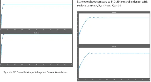
The waveform of three level boost converter with PID controller is shown below. TLBC with PID controller has no overshoot, PID controller is designed with PID constant,
[image:5.595.302.565.74.320.2]Kp =0.004, Ki=160.5e-6 and Kd=1e-6
Figure 9: PID Controller Output Voltage and Current Wave Forms
Figure 10: Simulink Block of PID Controller
D. Simulink Block and Waveforms of TLBC with SMC controller
The waveform of three level boost converter with SM controller is shown below. TLBC with SM controller has little overshoot compare to PID .SM control is design with surface constant,Kp1 =3 and Kp2 =30
[image:5.595.42.282.93.247.2] [image:5.595.39.564.407.693.2]© 2016, IRJET | Impact Factor value: 4.45 | ISO 9001:2008 Certified Journal | Page 488 Figure 12: Simulink Block of SMC Controller
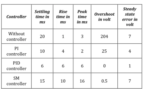
Table 1. Comparison between Sliding Mode Control, PI Control & PID Controller
Controller
Settling time in ms
Rise time in
ms
Peak time in ms
Overshoot in volt
Steady state error in
volt
Without
controller 20 1 3 204 7
PI
controller 10 4 2 25 4
PID
controller 6 6 6 0 1
SM
controller 15 10 16 0.5 7
V. CONCLUSION
In this paper PID control, PI control and sliding mode controller (SMC) is designed for three level boost DC-DC converter. After converter modelling and controller design, the simulations have been carried out in Matlab/Simulink software. The simulation result gives the validity of the all converter controller model. The robustness of sliding mode control is tested. The comparison of PID Controller with PI Controller and SMC has analyzed and the performance of PID is good compare to other controller in this three level boost converter.
REFERENCES
[1] T.A. Maynard and H. Foch, Multilevel conversion: high voltage choppers and voltage source inverters, in Proc. of IEEE Power Electron. Spec. Conf., 1992, Vol. 1, pp. 397- 403.
[2] J. S. Lai and F. Z. Peng, Multilevel converters- A new breed of power converters, lEEE Trans. Ind. Application, vol. 32, pp. 509-517, 1996.
[3] J. C. Rosas-Caro, J. M. Ramirez, P. M. Garcia-Vite, Novel DC-DC Multilevel Boost Converter, IEEE Pow. Elect. Special. Conf. (PESC 2008), vol., no., pp.2146-2151, 15-19 June 2008.
[4] V. I. Utkin, Sliding mode control design principles and applications to electric drives, IEEE Trans. Ind. Elec, vol. 40, No. 1, 1993.
[5] J. Y. Hung, W Gao and J. C. Hung, Variable Structure Control: a Survey,\ IEEE Trans. Ind. Elec., vol. 40, No. 1, pp. 2-22, 1993.
[6] Mohamed B. Debbat, Hafid A. Bouziane and Rochdi Bachir Bouiadjra.” Sliding Mode Control of Two-Level Boost DC-DC Converter” 978-1-4673-6673-1/15/$31.00 ©2015 IEEE.
[7] Mattavelli, L. Rossetto And G. Spiazzi ,Small Signal Analysis Of Dc-Dc Converters With Sliding Mode Control, IEEE Transaction on Power electronics, March 1995.
[image:6.595.47.291.344.495.2]