International Journal of Emerging Technology and Advanced Engineering
Website: www.ijetae.com (ISSN 2250-2459, ISO 9001:2008 Certified Journal, Volume 4, Issue 9, September 2014)
608
Study of Fork Tube Failure in Motorcycle Using Scanning
Electron Microscope
Sudhir Pawaskar
1, Prabhakar M. Bhovi
21,2
Assistant Professor, Department of Mechanical Engineering B.V. Bhooomraddi College of Engineering and Technology-Hubli, Karnataka
Abstract— Fork tubes, in motorcycles forms the front suspension assembly allowing the front tyre to maintain contact with the road for better handling and braking. Motorbike forks are generally made from cold drawn seamless tube of alloy steel ( as per BIS specification) with a coating of hard chrome. Fork tube failure of motorcycle is one which would cause injury and even death. The study of fractured surface founds to be an important aspect in order to
study the component chemical composition and
microstructure of the fork tube of the motorcycle to minimize the effect for impact load.
The present work has been carried out by the
characterization of the fractured surface through
micrographs and fractographs, of the fractured/pre-fractured surface of the fork tube using Scanning Electron Microscopy(SEM) and Energy dispersive spectroscopy (EDS). It is observed that there was a substantial variation in the primary composition of the fork tube with increased Carbon % (Mass %) which surprisingly measures to 29% at the fractured area when compared to 3.23 % at pre-fractured area. Resulting to this the specimen had undergone brittle fracture.
Keywords— Fork Tube, SEM, Fractography,
Microstructure.
I. INTRODUCTION
The current study is a fractured analysis, carried out on the fractured fork tube. Fork tube is an integral part of a motorcycle’s front (telescopic) suspension system. It connects the front wheel and axle to its frame. Fork tube compresses and extends to adjust for inconsistencies on the
road allowing the front tyre to maintain contact with the
road for better handling and braking. The specimen was obtained from a local client. The motorbike was subjected to impact loading (in form of accident) cause of which the specimen underwent premature fracture. Hence the metallurgical analysis was needed to understand the cause of failure.
Components of a system can fail one of many ways, for example excessive deformation, wear, rupture, corrosion, burning-out, degradation of specific properties. The credibility of failure analysis lies in their ability to identify corrective actions by determining the causes of the failure.
Hence the following study is an effort to understand the root cause of the failure in the fork tube of motorbike by carrying out various metallurgical observations in the form of SEM and EDS analysis.
II. EXPERIMENTAL PROCEDURE
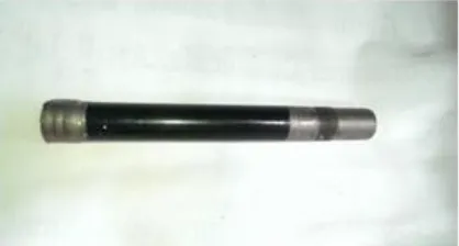
[image:1.612.340.549.464.576.2]When failed components are received in the laboratory it is customary to document their condition. The failed fork tube was received from client, which was of 202 mm length, 26 mm diameter and thickness of 4 mm with fractured surface at one end. (As shown in figure 2.1 and 2.2.1). The specimen was kept in open atmosphere in a polyethene bag. The Specimen of the fractured fork tube is as shown in Fig 2.1
International Journal of Emerging Technology and Advanced Engineering
Website: www.ijetae.com (ISSN 2250-2459, ISO 9001:2008 Certified Journal, Volume 4, Issue 9, September 2014)
609
[image:2.612.104.234.490.629.2]2.1 Preparation For Post Facture Sample
Figure 2.1.1 of post fractured sample after finishing operation The fractured fork tube was cut to a length of 10 mm using high precision blade cutter with oil-water emulsions as coolant so that no phase transformation is observed due to the heating by the cutting operation carried out on the specimen surface. Then the sample was carefully brushed with the cotton using acetone to clean the dirt particles from the fractured surface. The sample was well preserved by covering with cotton and placed in desiccators.
Precautions were taken to avoid any possible
environmental influence that could affect the specimen.
2.2 Preparation For Pre Facture Sample
The same fractured fork tube at a distance of 75mm from fractured was cut to a length of 8 mm using high precision blade cutter with oil-water emulsions as coolant so that no metallurgical phase change occurs during the process.
Figure 2.2.1 pre fractured sample after finishing operation The specimen, were then prepared for necessary metallurgical observations through SEM. The specimen were carefully polished using relevant polishing papers of grid sizes of 400, 600, 800, and 1000 to study the microstructure of the sample.
Initial polishing was carried out using 400 grid pad until the lines were completely in one direction on the observation face of the sample. Then with less pressure compared to before using 600 grid pad the sample was polished perpendicular to the lines observed from previous polish till the lines disappears. Similarly polishing is carried out with other grid pads till the mirror finish is obtained at the observation surface. Further the sample was polished using disc polishing machine by applying diamond paste and holding it against velvet cloth to obtain the good scratch free finish. The etchant NITAL 5% was used to etch the polished face in order to see grains structure using microscope. Then the sample was well preserved by covering with cotton and placed in dessicator which was initially cleaned using acetone to minimise environmental effect on it.
III. EXPERIMENTAL PROCEDURE
3.1Obsrevations
The Fractured Surface for the given specimen is as shown in the figures 3.1, 3.2 and 3.3. It clearly indicates the characteristic of bending and sheared surface caused by high sudden impact stress.
Figure 3.1
The area of final fracture is large, of total area, indicating that the material had undergone severe deformation by twist/Bending. The beachmarks (Figure 3.3) and striations observed indicates the nature and characteristics, fracture that had propagated from from the initiation site, and the location of final fracture(fig 3.1).
[image:2.612.387.500.599.705.2]International Journal of Emerging Technology and Advanced Engineering
Website: www.ijetae.com (ISSN 2250-2459, ISO 9001:2008 Certified Journal, Volume 4, Issue 9, September 2014)
[image:3.612.394.494.120.212.2]610
Figure 3.3
Initiation of fracture occurred around the circumference of the fork tube. The bending of a fork tube near the fracture surface till the depth of 14mm from the fractured end clearly indicate the load was nearly perpendicular to axis of the fork tube (Figure 3.1).
Clearly the shearing lines at initial point of contact with the fork tube are visible (Figure 3.3). The bulging at the surface of facture shows that the circular cross-section was changed to elliptic due to sudden impact load before the specimen was fractured (Figure 3.2). Due to bulging the thickness of the fork tube has changed from 4mm to 2mm at fractured surface (Figure3.2).
3.2. SEM Analysis
3.2.1. Pre Fracture Surface
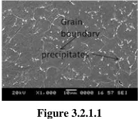
The microstructure analysis was carried out for the samples involving both pre fractured and post fractured surface of the fork tube using Scanning Electron Microscope (JSM-6380LA, JEOL, JAPAN). The Figure 3.2.1-1 shows the pre fractured sample which has been observed using SEM. The fork tube end was prepared for
metallurgical studies, after appropriate polishing
[image:3.612.111.227.125.241.2] [image:3.612.394.493.268.353.2] [image:3.612.391.490.386.473.2]procedures.
Figure 3.2.1.1
[image:3.612.119.218.523.626.2]The microstructural examination carried out on the specimen at 1000X,4000X and 10,000X reveals fine grain structure of the material with some precipitates observed as being distributed evenly throughout the grain-boundries.
Figure 3.2.1.1
This can be seen in Fig 3.2.1.2 and 3.2.1.3. This result can be accommodated to the presence of large quantities of cementite at the Grain baundry region and pearlite at the grain.
Figure 3.2.1.1
The grain size distribution can be seen as uneven relating to heterogeneous microstructures (Figure 3.2.1-2).
Figure 3.2.1.1
The same can be observed from figure (3.2.1.4)
3.2.2. Pre Fracture Surface
Subsequently the given fractured specimen were observed under SEM, to understand the nature of fracture, as shown below. The images shows dimples at the fractured locations, which could possibly be due to the intergranular fracture (Figure 3.2.2-2). Figure 3.2.2-4 shows microstructure of intergranular fracture on the elliptical edge. This might be possibliy because of high C, which hence form Carbides at the grain baundries being present at the fractured location and can be validated through the EDS analysis shown in fig(3.3.2.2)
International Journal of Emerging Technology and Advanced Engineering
Website: www.ijetae.com (ISSN 2250-2459, ISO 9001:2008 Certified Journal, Volume 4, Issue 9, September 2014)
611
3.3. Elemental Analysis
The element analysis was carried out at SEM using Energy Dispersive Spectrometer for both the samples in-order to understand the composition and amount of various allowing elements for both pre-fractured and fractured specimen. The results obtained shows high amount of C which were present undiluted in the metal matrix of iron. The result looks very surprising. The high C composition in the tube may be correlated to improper/flaw involved during the manufacture of the tube. The results obtained are as shown in below.
3.3.1.Pre Facture Sample
Figure 3.3.1-1
[image:4.612.329.551.122.261.2]
Figure 3.3.1-2: shows the graphical result of EDS analysis carried out at certain area (Figure 3.3.1-1) of pre fractured surface. The following is the table showing the composition of sample tested for EDS
From the EDS analysis the presence of 3.23 percentage by mass indicates its high carbon steel. The presence of remaining alloys quantity was found to be less. By the composition the alloy is brittle in nature.
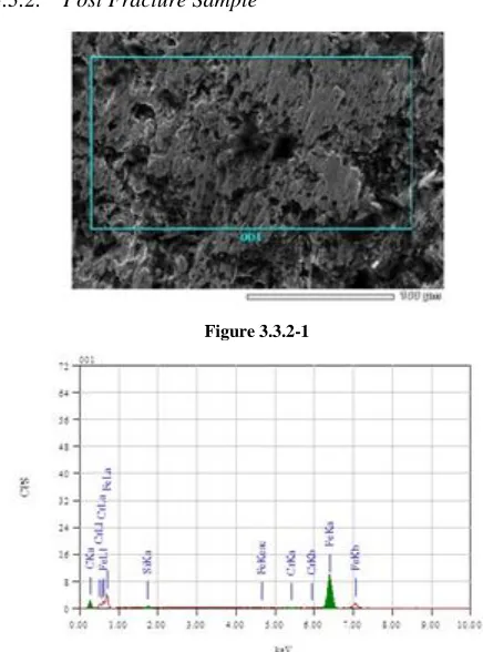
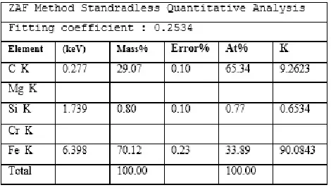
[image:4.612.328.546.376.670.2]3.3.2. Post Fracture Sample
Figure 3.3.2-1
International Journal of Emerging Technology and Advanced Engineering
Website: www.ijetae.com (ISSN 2250-2459, ISO 9001:2008 Certified Journal, Volume 4, Issue 9, September 2014)
612
Table showing percentage by mass of composition of post fractured sample
EDS analysis shows the carbon content increased from 13.38% to 65.34% by atomic weight stating that material’s brittleness was increased at fractured surface of the component, hence the sample has undergone brittle fracture.
IV. CONCLUSION
It is concluded from the study of failed fork tube of motorcycle are:
1.The sequence of failure of the fork tube due to sudden
impact loading was initially bent due to its elasticity, and then crack was initiated and propagated, to fracture.
2. The microstructure of the pre fractured surface sample
was observed, the grains are not uniform and it was
heterogeneous state. The fractured surface also
observed through SEM, showed the presence oxides.
3. By the composition analysis it was found that due to
increase in the carbon percentage in the material at fractured surface, the sample’s brittleness was increased. The carbon percentage was increased due to environmental condition, may be due to entrapment of carbon particles concentrated at the fractured surface, failed component might have kept open for longer duration and the type of impact load. Hence component failed as brittle facture.
REFERENCES
[1] The effect of vehicle roadworthiness on crash incidence and severity
by George Rechnitzer, Narelle Haworth, Naomi Kowadlo.
[2] SEM in failure analysis by Shaiful Rizam Shamsudin, Bangi, 43000
Kajang, Selangor, Malaysia.
[3] Material science and engineering – An Introduction by William D.
Callister, Jr. published by John wiley & sons, Inc.
[4] Introduction to Scanning Electron Microscope -theory, practice, & procedures by Micheal Dunlap and Dr. J.E. Adaskaveg.
[5] An introduction to failure analysis for metallurgical engineers by Thomas Davidson.
[6] Failure analysis of engineering structures–Methodology and Case
[image:5.612.52.287.124.259.2]