© 2015, IRJET.NET- All Rights Reserved
Page 403
Comparative Study of Microstrip Rectangular Patch Antenna on
different substrates for Strain Sensing Applications
Neeraj Sharma
1, Vandana Vikas Thakare
21,2
Department of Electronics, Madhav Institute of Technology & Science, Gwalior-05
---***---Abstract -
The feasibility of applying patchantennas for strain sensing is investigated. The resonant frequency of microstrip patch antenna is calculated by the dimensions of its patch. In this work, three types of microstrip patch antennas are developed using three different substrates FR4, RT
Duroid 5880 and Polyimide.This paper describes the
simulation of a slotted rectangular microstrip patch antenna for strain measurement for three different materials. The microstrip antenna is designed and simulated using Computer Simulation Technology (CST) Microwave Studio. The dimensions of slotted patch antenna are changed when the antenna is under strain, resulting in shift of its resonant frequency. Hence, the applied tensile strains can be measured from the shift in resonant frequency. The resonant frequency of the microstrip patch antenna decreases linearly with the increase of applied strain along the length direction of antenna.
Key Words:
Computer Simulation Technology (CST),
Microstrip antenna, Strain sensor, Polyimide.
1. INTRODUCTION
The recent developments in area of structural health monitoring have been tremendous and the need is constantly increasing in the area. Growth in this area has been able to develop structural health monitoring systems using various techniques. But many of the techniques are still not able to monitor conditions in a complex operational aerospace structure. Hence there is always a need to investigate on techniques and methods to develop wireless sensors which are reliable and efficient enough to be used in complex environments and applications.
As previously studied by Daliri Ali [1], the current available wireless sensors are not efficient enough to be used in structural health monitoring for aerospace structures primarily due to high cost and battery power limitations.
The focus of this work is to make a preliminary study in the laboratory to investigate the feasibility of using a microstrip patch antenna as a sensor for stain sensing applications as it can be a wireless sensing technique. The patch can be rectangular, circular, elliptical or of any other shape. In this paper a slotted rectangular patch antenna is considered due to its simplicity. The advantages of the microstrip patch antenna lies in the fact that it is light in weight, low fabrication cost and ease of fabrication.
Analytical computation and experiments have been verified by Daliri [1], using a circular patch antenna in which the resonant frequency of a patch varies uniformly in every direction with applied strain. It is presented that there is a linear relationship between the strain and the percentage of resonant frequency shift regardless of the materials used for antenna manufacturing [2]. On other hand, U Tata [3] using a square patch antenna in which the resonant frequency of a rectangular patch antenna depends on its length and width.
In this paper, three different substrates are used and their sensitivity to applied strain is investigated. The analysis is carried on two flexible substrates namely polyimide and RT Duroid 5880 and a non-flexible substrate FR4.
2. ANTENNA DESIGN AND PRINCIPLE OF
OPERATION
2.1
Resonant Frequency
© 2015, IRJET.NET- All Rights Reserved
Page 404
(1)Where c is the velocity of light The electrical length Le of
the antenna is defined as the dimension of the metallic patch along the direction of the radiation mode.
Dielectric Substrate
Metallic Patch
L
W
h
Ground
Fig -1: Patch antenna
The effective dielectric constant εre is related to
the dielectric constant of the substrate εr, the substrate
thickness h and the electrical width of the patch e [5],
(2)
The line extension Loc is calculated from the effective
dielectric constant εre , the substrate thickness h and the
electric width ,
(3)
Assuming the antenna is subjected to a tensile strain εL
along its electrical length direction, the patch width and the substrate thickness will change due to Poisson’s effect, i.e.,
and h = (1- (4)
Therefore, the resonant frequency in equation (1) can be expressed as
fres = (5)
where
and
The strain-induced elongation, therefore, will shift the antenna resonant frequency. At an unloaded state, the antenna frequency f res0 is calculated from the antenna length Le0 and substrate thickness h0, i.e.,
(6)
Under a strain εL , the antenna frequency shifts to
(7)
By using equation (6) and (7)., the relation between shift in resonant frequency and strain is given as:
= = - (8)
Where is the strain, the resonant frequency varies in an opposite direction to that of strain outside, so the strain can be obtained through the variation of the resonant frequency, then the microstrip patch antenna becomes a strain sensor.
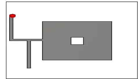
2.2 Design and Simulation
In this paper a slotted rectangular microstrip patch antenna has been designed using CST Microwave Studio. There are three different materials used to design the slotted patch antenna. The three substrates are FR4 (lossy), Rogers RT Duroid 5880 and Polyimide with the permittivity 4.3, 2.2 and 3.5 respectively. The simulation results of antenna with same dimensions and different materials are shown in figure
[image:2.595.35.254.197.384.2] [image:2.595.321.560.596.733.2]
© 2015, IRJET.NET- All Rights Reserved
Page 405
Fig -3: Return loss of the rectangular patch antennausing FR4 substrate without strain
Fig -4: Return loss of the rectangular patch antenna using RT Duroid 5880 without strain
Fig -5: Return loss of the rectangular patch antenna using Polyimide without strain
3. RESULTS AND DISCUSSION
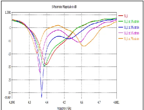
Different amount of strain was subjected to the three designed antennas with unlike materials and the return loss is plotted. It is seen, that when the tensile strain is applied on the slotted patch antenna, the lengths of the rectangular patch antenna change. Figure 6, figure 7 and figure 8 show the simulation results when the patch antenna is strained with different loads. A clear shift in the resonant frequency can be seen in the simulated results. On the comparison of three substrates it is found that the Rogers RT Duroid 5880 is the most sensitive to the applied strain among the three substrates.
Fig -6: Return loss of the rectangular patch antenna using FR4 substrate with strain
[image:3.595.38.267.120.255.2] [image:3.595.314.544.283.459.2] [image:3.595.36.276.331.481.2] [image:3.595.315.555.510.684.2] [image:3.595.38.271.532.685.2]© 2015, IRJET.NET- All Rights Reserved
Page 406
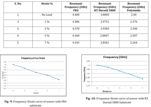
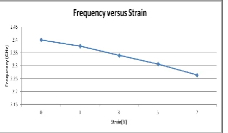
Fig -8: Return loss of the rectangular patch antenna using Polyimide substrate with strainFigures 9-11 illustrate the linear fitting of the resonant frequency and the applied strain for the slotted patch antenna subjected to length direction deformation. There is an tremendous linearity between the resonant frequency and the strain for flexible material antenna sensors. The slope of curve signifies the resolution of antenna sensor. The antenna sensor has more sensitivity at high initial resonant frequency, along with the larger dimension of the antenna patch as well, and the simulated results are in good concurrence with the theoretical study.
Table 1: Simulation Results for Applied Strain versus Resonant Frequency (GHz)
S. No. Strain % Resonant
Frequency (GHz) FR4
Resonant Frequency (GHz)
RT Duroid 5880
Resonant Frequency (GHz)
Polyimide
1. No Load 4.400 3.0005 2.40
2 1 % 4.386 2.9751 2.376
3. 3 % 4.370 2.9303 2.340
4. 5 % 4.360 2.8847 2.307
5. 7 % 4.343 2.8361 2.264
[image:4.595.37.306.95.272.2]Fig -9: Frequency-Strain curve of sensor with FR4 substrate
[image:4.595.36.554.298.666.2]© 2015, IRJET.NET- All Rights Reserved
Page 407
Fig -11: Frequency-Strain curve of sensor withPolyimide Substrate
4. CONCLUSION
The simulation results and theoretical results confirm the linearity between the resonant frequency shifts of slotted rectangular patch antenna and the strain. Therefore, it is possible to use rectangular patch antenna fabricated on a flexible substrate (RT Duroid and Polyimide) to be used as a strain sensor in Structural Health Monitoring and Biomedical application
REFERENCES
[1] Ali Daliri, Amir Galehdar, Sabu John, Wayne Rome, Kamran Ghorbani, “Circular microstrip antenna strain sensor for wireless structural health monitoring”, Proceedings of the World Congress of Engineering, vol 2. 2010.
[2] A. Daliri, A. Galehdar, S. John, C. H. Wang, W.S.T. Rowe and K. Ghorbani, Wireless Strain Measurement Using Circular Microstrip Patch Antennas, Sensors and Actuators A: Physical, vol. 184, (Jul.) 2012, pp 86-92.
[3] U.Tata, H.Huang, R L Carter and J C Chiao, “Exploring a patch antenna for strain measurements”, Measurement Science and Technology, vol.20, IOP Publishing, 2009.
[4] P. Bhartia, K. Rao and R. Tomar, Millimeter-Wave Microstrip and Printed Circuit Antennas, Boston, Artech House Press, 1991.
[5] C. Balanis, Antenna Theory: Analysis and Design (3rd edn) , New York, Wiley Press, 2005.
[6] CST Microwave Studio, “Overview and work flow”, CST1998-2010.
BIOGRAPHIES
Neeraj Sharma completed his B.Tech. from HCST, Mathura. He is currently pursuing M.Tech. in Microwave Engineering from MITS, Gwalior. His research interest includes Microwave Communication and their applications.
Dr. Vandana V. Thakare