Design of Fuzzy controller and supervisor for Load
Frequency control of Micro Hydro Power Plant
Suhas V. Kamble
*, D.P. Kadam
***
Electrical Engineering, K.K. Wagh I.E.E. & R., Nasik, India **
Electrical Engineering, K.K. Wagh I.E.E. & R., Nasik, India
Abstract- The job of automatic frequency regulation is achieved by governing systems of individual turbine generators and Automatic Generation Control (AGC) or Load frequency control (LFC) system of the hydro power plant. This seminar report addresses a comprehensive literature survey on load frequency control in hydro power plant. The report is aimed to present the various control and structural schemes of LFC present in the microhydro power plant. The LFC schemes on different aspects like classical control based LFC schemes, LFC schemes based on modern control concepts are discussed.The aim of the proposed work is to design a fuzzy controller that would manage almost the whole operation of the generating unit. The presented fuzzy controller has three main tasks. First, it regulates the frequency output of the plant in spite of changing user loads. Second, it limits the waste of the available water. Finally, it manages the electricity distribution by dividing the mini network on different departures connected in order of priority.
Index Terms- Automatic generation control, Load frequency control, hydro power plant, linear and nonlinear turbine model, adaptive fuzzy controller.
I. INTRODUCTION
C
limate change, global warming, population growth and the continuous demand for energy and electricity have made Renewable Energy the most appropriate and fitting to answer all these changes in our environment. The scientific community is widely interested in modeling and control of renewable energy plants as the number of published papers do not cease increasing since the last decade, specifically on hydro and micro-hydro power plant. Micro-hydro power plants (MHPP) are of big interest in their easiest installation and their affordability. They are located in mountainous areas where hydropower resources are available. A typical MHPP includes a mountain reservoir, a penstock, a powerhouse and an electrical power substation. The reservoir stores water and creates the head; the penstock carries water from the reservoir to a turbine inside the powerhouse. The water rotates the turbine, which drive a generator that produces electricity. A hydraulic turbine is a hydropower machine that directly converts the hydraulic power in moving water into mechanical power at the machine shaft.Further, MHPP are often isolated, inaccessible and are not connected to the national grid. So, when a MHPP stop working for any reason, it deprives the local population from electricity. An intervention to make it operational takes a long time, and might be impossible in case of inclement weather. This
requires the control system to be autonomous, robust and capable of managing all operational situations.
Due to alterations of the grid load, deviations are caused between turbine power output and the load. The frequency output of MHPP and the voltage may drastically vary from their nominal value. Thus, MHPP needs control to maintain an uninterrupted power at rated frequency and voltage. It should keep the rotational speed of the turbine generator unit stable around its nominal value for any grid load and prevailing conditions in the water conduit.
Turbine governors are systems for the control and adjustment of the turbine power output and for evening out deviations between the power and the grid load as quickly as possible. Two main governors are used to automatically control the frequency of the generating unit). First, it could remain constant by action on the gate opening position to produce just the necessary power according to the connected\ load. Second, electronic load controllers (ELC) govern the frequency by adjusting the electrical load connected to the alternator. Therefore, they maintain a constant electrical load on the generator in spite of changing users' load. In this case, the turbine gate opening is kept in a specific position that guarantees a nominal mechanical power at the generator shaft. It permits to use turbine with no flow regulating devices. The former governor takes a long time to stabilize the output and it becomes insufficient in case of large load variations where the stability of the system could be completely lost. ELC is used in order to simplify the MHPP control. The stabilizing time is short even for large load variations.
However, ELC waste precious energy that can be used gainfully. Also they do not carry out flow control, implying that the mineral rich water is made to spill away, which could have been diverted at high heat for irrigation purposes. We have presented a TS fuzzy controller to maintain the MHPP frequency constant using an ELC governor and to adjust the water flow to limit the dissipated power on the ballast load.
In the other hand, there are other effects that cause fluctuations of the frequency on a grid load. For example, the level of water in the reservoir might change significantly depending on the season, which would directly affect the MHPP output frequency. Even for a certain level of water, the users might connect machines that require high levels of power causing a large drop of frequency. Thus, an effective control scheme has to take into account those operation cases in order to insure a good level of control.
provides good results in control of power systems. This paper aims to use fuzzy control to insure good control of isolated MHPP. The proposed control scheme is suitable for turbine systems with both guide vane governors and synchronous generators, especially permanent magnet machines which have no automatic voltage regulator.
The rest of this paper is structured as follows: section II presents both the problem formulation of frequency fluctuation by that of random power fluctuation at generation and load sides, and the proposed control scheme to overcome frequency fluctuation for any working condition. Dynamic model of the MHPP is briefly introduced in Section III. Design methodology of the proposed fuzzy control system that consists of a fuzzy controller and a fuzzy supervisor is described in Section IV. Simulation results are provided lastly to valid the new control scheme followed by a conclusion in section VI.
II. PROBLEM FORMULATION.
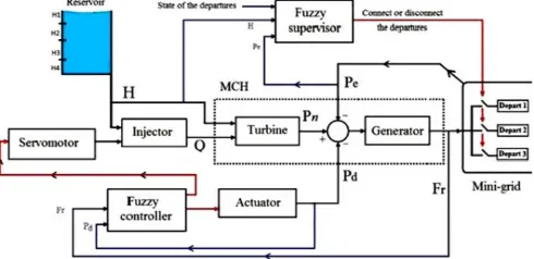
Since frequency fluctuation is effected mainly by the fluctuation of real power, power quality problems threatening the frequency stability can be solved or avoided by satisfying the real power supply. The problem addressed in this paper is to find a fuzzy control law that maintains the MHPP frequency output and voltage stable around their nominal value and optimizes the available water in the reservoir, which will economize and reduce its waste. To achieve our objective, the fuzzy logic has been used for its ability to easily incorporate the human expertise, and to use the traditional methods of analysis and stability. A fuzzy supervisor is added to manage the operation of the MHPP, as shown in Figure 1.
[image:2.612.40.285.581.700.2]The guide vane governors should be relatively slow to avoid water hammer effect. Thus, with the presence of a large and sudden load discharge, the control law, based on the variation of the gate opening position, would be unable to quickly reduce the produced power. In the proposed control scheme, the fuzzy controller controls an ELC actuator in order to compensate the disconnected load by dispelling the excess produced power on the ballast load (noted "Pd"). In order to avoid wasting available water in the reservoir, the proposed fuzzy controller is able to reduce the power dissipated to a very low value once the system stabilizes, this, by closing the gate position via a servo motor that governs the water flow.
Figure 1: The proposed control scheme.
The produced electrical power depends on the level of water existing in the reservoir. To avoid problems, overloading of the MHPP or insufficient water, the mini- grid network fed by the MHPP is divided into a set of sub- networks (departures) that are powered by order of preference. For example, when very large overloads are caused, the proposed supervisor disconnects the less preferential departures to avoid large drop of frequency. The supervisor also manages the distribution of electricity between these departures depending on the availability of water in the mountain reservoir.
III. THE MICRO HYDRO POWER PLANT MODEL MHPP is a non-linear, non-stationary multivariable system whose characteristics vary significantly with the unpredictable load on it and this presents a difficulty in designing efficient and reliable controllers. However, the majority of the proposed hydro power models is linear. A linear model representation of the turbine system is valid only for small signal performance study (load disturbance <±10%). This makes model an oversimplified and realistic issue not being discussed. Such a linearized model is inadequate for large variations in power output (>±25% rated load).
This model is based on the mathematical equations resuming the whole operation of MHPP. It incorporates nonlinear equations of the mechanical power; the electrical consumed power and the relationship between the turbine flow, the turbine head and the frequency of the voltage waveform. The two equations that summarize MHPP operation are:
√
(1)
(2)
Where: fr is the MHPP frequency; qt is the water flow; ht is he head; pt is the turbine power; pe is the load; kt and Ta are constants that characterize the plant.
IV. THE DESIGN OF MHPP FUZZY CONTROLLER AND SUPERVISOR MODEL
In this section, the proposed control system is designed and simulated to be used as a global control system for MHPP, which may replace PID hydraulic turbine governors, and is able simultaneously to control the MHPP frequency and to manage the whole operation of the plant under nonlinear process conditions.
To design a fuzzy controller reliable and smart enough, the design has to rely not only on an accurate MHPP modeling, but also on an “expert knowledge base”. The expert knowledge base comprises technical information on hydraulic turbine operation and control gathered from expert people who work in this field, reported and or published articles, field trials, simulation and predictions. It may also cover some hidden dynamics not modeled.
control is a somewhat intelligent, cost-effective nonlinear control. Different types of adaptive fuzzy logic controls such as self-tuning and self-organizing controllers can be found. The combination of a PI control and a fuzzy control strategy means that PI control has nonlinear characteristics and intellectual faculties, and simultaneously endows fuzzy control with an established PI- control configuration. The fuzzy self-tuning controller readjusts the PI gains in real-time to improve the process output response, during the system operation.
A. Fuzzy Controller
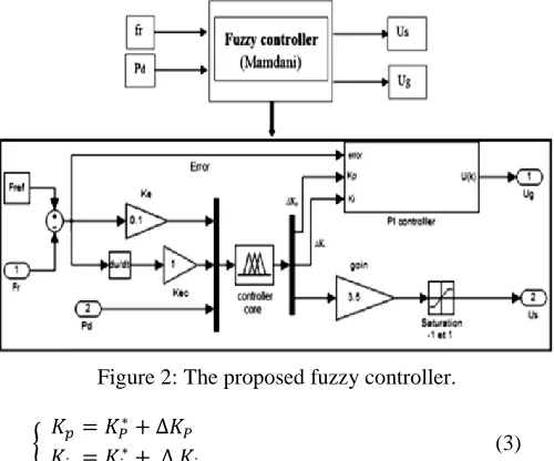
Figure 2 shows the proposed fuzzy controller. It has two outputs. The first one, "Ug", acts on an ELC in order to maintain the frequency on its nominal value. The second output, "Us", acts on a servo motor that varies the water flow for two cases: when the frequency of the MCH goes away from its nominal value and whenever the electrical power "Pd" exceeds a certain limit value, chosen for our simulation studies to be 20% of the nominal turbine power.
[image:3.612.46.296.350.558.2]Due to the strong nonlinearity of MHPP, a PI or PID controller would be incapable to ensure good stability of the plant all over its operating range. Thus, the proposed fuzzy controller has been designed to adjust on-line the parameters of proportional gain Kp and integral gain Ki of a PI controller based on the error e and the change of error Δe
Figure 2: The proposed fuzzy controller.
{
(3)
Where Kp* and Ki* are the reference values of the controller. They will be adjusted online by the fuzzy controller outputs ΔKp and Δ Ki. Therefore, the PI controller action is updated after each cycle time. The error e and the change of error Δe are used as numerical variables from the real system. To convert these numerical variables into linguistic variables, seven fuzzy sets are chosen for e: negative big (NB), negative medium (NM), negative small (NS), zero (Z), positive small (PS), positive medium (PM), and positive big (PB); and three fuzzy sets are chosen for Δe: negative (N), zero (Z), positive (P).
On the other hand, the proposed fuzzy controller is synthesized to govern via a servo motor the gate opening of the turbine. It closes the gate opening, not only when the frequency exceeds its
nominal value, but also when Pd exceeds the defined limit. This task can be summarized by the following rules:
if e is Positive and Pd < Pd limit then Us is Positive
if e is Positive and Pd > Pd limit then Us is Positive
if e is Negative and Pd < Pd limit then Us is Negative
if e is Negative and Pd > Pd limit then Us is Negative
if e is Zero and Pd < Pd limit then Us is Zero
if e is Zero and Pd > Pd limit then Us is Negative Where: e is Positive when Fr<50Hz; e is Negative when Fr>50Hz; e is Zero when Fr=50Hz; Us Positive order to open the gate opening; Us Negative order to close the gate opening; Us is Zero: position of the gate opening remain unchanged.
The fuzzy membership functions for the fuzzy controller input parameters (e, Δe and Pd) and output parameters (Us, ΔKp and ΔKi) are shown in figure 3. The initial values of Kp* and Ki* are 0.1 and 0.3 respectively. Ke and Kec are 0.04 and 10 respectively in the figure 2.
[image:3.612.327.579.381.670.2]The controller core is the fuzzy control rules which are mainly obtained from intuitive feeling and experience. The design process of fuzzy control rules involves defining the rules that relate the input variables to the output model properties. The inference method employs the MAX– MIN method. The imprecise fuzzy control action generated from the inference must be transformed into a precise control action in the application. The center gravity method is used to defuzzify fuzzy variables into their physical domains.
Figure 3: Fuzzy controller’s membership function
B. Fuzzy Supervisor
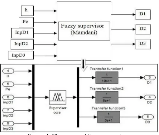
undesirable situations might be occurred, where the generating unit would be no longer able to feed th consumer loads connected to the mini-grid. To remedy this possible situation, the proposed fuzzy supervisor, presented at the figure 4, is able either to disconnect or connect the less preferred departures, depending on the level of the available water.
Figure 4: The proposed fuzzy supervisor.
The level of water "h" is divided into four sets (H1, H2, H3, H4) while the departures of the grid are three (D1, D2 and D3). D1 is the more preferential departure while D3 is the less preferential. This task, assured by the fuzzy supervisor, can be summarized by the following rules:
if h is H1 then D1, D2, and D3 are connected.
if h is H2 then D1 and D2: connected, D3: disconnected.
if h is H3 then D1 connected, D2 and D3: disconnected.
[image:4.612.314.577.217.613.2] if h is H4 then D1, D2, and D3 are disconnected.
Figure 5: Fuzzy supervisor's membership functions.
Furthermore, the proposed fuzzy supervisor manages the electrical production between the three departures. The division of the mini-grid into different departures will be also used by the proposed supervisor to limit the consumed power "Pe", to make sure that it never exceeds the turbine power. Whenever very large overloads are caused by the users, where the load exceeds the produced power, the fuzzy supervisor disconnects the less preferential departures (D3) to avoid large drop of frequency. If the consumed power still exceeds the turbine power, the supervisor disconnects other less priority departure (D2) and so on. The fuzzy membership functions for the fuzzy supervisor input parameters (h, Pe, ImpD1, ImpD2 and ImpD3) and output parameters (D1, D2 and D3) are shown in figure 5.
(a) Experimental results
(b) Simulation results
V. CONCLUSION
the waste of water by limiting the dissipated power on the ballast load. The fuzzy supervisor manages to use the available water based on consumer demand. Even for random and large load variations, the proposed control system keeps good dynamics as expected. Simulation results show the feasibility of the proposed fuzzy control system.
REFERENCES
[1] I. H. G. M.Hanmandlu, Member and I. D.P.Kothari, Senior Member, “An advanced control scheme for micro hydropower plants,” IEEE Trans. , 2006. [2] D. Shrestha and A. B. Rajbanshi, “An advanced control scheme for micro hydropower plants,” Fifth International Conference on Power and Energy Systems, Kathmandu, Nepal, October 2013.
[3] M. T. G. Ebruzbay, “Self-tuning fuzzy pi controlled system model for small hydro power plants,” 10th International Conference on Clean Energy ICCE Famagusta, N. Cyprus, September 2010.
[4] P. K. R. A. Priyabrata Adhikary, SusmitaKundu, “Fuzzy logic based user friendly Pico-hydro power generation for decentralized rural electrification,” International Journal of Engineering Trends and Technology , 2013.
[5] M. M. Umrao, Sanjeev Kumar and D. K. Chaturvedi, “Load frequency control methodologies for power system,” 2nd International Conference on Power, Control and Embedded Systems, 2012.
[6] T. G. Ebru6zbay Muhsin, “Load frequency control for small hydro power plants using adaptive fuzzy control,” IEEE Trans. , 2010.
[7] K. R. Neethu John, “An overview of load frequency control strategies: A literature survey,” International Journal of Engineering Research Technology (IJERT) , 2012.
[8] I. Hassan Bevrani, Senior Member and I. Takashi Hiyama, Senior Member, “On load-frequency regulation with time delays: Design and real-time implementation,”IEEE Transactions On Energy Conversion , 2009.
[9] I. Hassan Bevrani, Senior Member and P. R. Daneshmand, Comparison of Conventional PID Tuning of Sliding Mode Fuzzy Controller for BLDC Motor Drives. IEEE Trans., 2012.
[10] M. R. Zohra Zidane, Mustapha AitLafkih, “Simulation studies of adaptive predictive control for small hydro power plant,” Journal of Mechanical Engineering and Automation , 2012.
AUTHORS
First Author – Suhas V. Kamble, B.E Electrical Pune, P.G student M.E (Electrical) Control system, K.K. Wagh I.E.E. & R., Nasik, India, [email protected]