2019 International Conference on Artificial Intelligence, Control and Automation Engineering (AICAE 2019) ISBN: 978-1-60595-643-5
Calculation of Lightning Level of Transmission Line Tower Using
Graphite Grounding Device
Hong-peng LI
1,*, Wen-qing XU
2, Bin YE
1and Jin-ma SHENG
11State Grid Anhui Electric Power Co., Ltd. Economic Technology Research Institute, Hefei City,
Anhui Province, 230071, China.
2State Grid Anhui Electric Power Co., Ltd. Hefei Power Supply Company, Hefei City,
Anhui Province, 230000, China.
*Corresponding author
Keywords: Lightning protection, Graphite grounding device, ATP-EMTP, Grounding resistance,
Lightning withstand level.
Abstract.In recent years, graphite grounding devices have developed rapidly and have been widely used in transmission networks. However, the main application is that they are highly corrosive to alkaline soils, and their research on conductivity and lightning resistance is insufficient. Therefore, this paper establishes the ground net model through the simulation software CDEGS, and calculates the power frequency grounding resistance of three different materials of graphite, steel and copper under different conditions and compares them. Using ATP/EMTP software, the calculation model of the lightning strike level including the tower tower, the line, the insulator flashover and the grounding resistance was established. The lightning resistance level of the transmission line tower using the graphite grounding device and the steel grounding device was calculated. Then verify the feasibility of the graphite grounding device.
Introduction
Towers play the role of supporting the conductors and ground lines of overhead transmission lines in the transmission process. Grounding device is one of the important components of tower. When tower is struck by lightning, grounding device can ensure that lightning current quickly leaks into the earth and plays a certain role in lightning protection. At present, China's traditional grounding devices are mostly made of metal materials such as steel and copper. However, the corrosion resistance of metal materials is poor, it needs to be replaced regularly, the cost is high, and it is easy to be stolen. As a form of carbon, graphite has a wide range of sources and relatively low price, and its performance in electrical and thermal conductivity is better than traditional metal materials [1]. In recent years, graphite materials have been widely used in power transmission tower grounding devices because of their high corrosion resistance[2-4]. However, their conductivity and lightning protection performance have not been fully exploited due to lack of theoretical basis [5-9]. Therefore, the use of graphite as a grounding material makes it necessary to study its electrical conductivity and lightning protection performance. In this paper, the power frequency grounding resistance of different materials under different conditions is calculated, and the influence of graphite grounding on lightning resistance level is analyzed, which shows the feasibility of graphite grounding device.
Grounding Resistance of Graphite Grounding Device
reduce the grounding resistance by using blasting grounding technology.
[image:2.595.114.483.164.247.2]The grounding resistance is related to factors such as soil resistivity, grounding type, and lightning current frequency, so they are compared separately. The relevant parameters of the three different grounding materials are shown in Table 1.
Table 1. Related parameters of copper, steel and graphite.
Number Relative
resistivity
Relative permeability
radius
/(m) material
Resistivity /(Ω·m)
1 1 1 0.01 copper 1.75×10⁻⁸
2 110 636 0.01 steel 1.92×10⁻⁶
3 1857 1 0.01 graphite 3.25×10⁻⁵
4 1857 1 0.022 graphite 3.25×10⁻⁵
5 1857 1 0.028 graphite 3.25×10⁻⁵
Establishment of Graphite Grounding Device Model
[image:2.595.231.365.322.451.2]The model of transmission line tower grounding device is established by CDEGS software. The form of grounding device is shown in Figure 1. The depth of grounding device is 0.8 meters, the length of box edge is 10 meters, the length of quadrangular epitaxy ray is 12 meters, and the soil is uniform.
Figure 1. Frame ray type grounding device diagram.
Grounding Resistance at Different Soil Resistivities
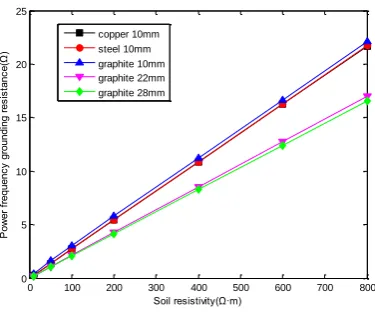
When soil resistivity is 10Ω·m, 50Ω·m, 100Ω·m, 200Ω·m, 400Ω·m, 600Ω·m and 800Ω·m respectively, the power frequency grounding resistance of three different materials, copper, steel and graphite, is simulated and calculated. The results are shown in Table 2.
Table 2. Grounding resistance of different grounding materials under different soil resistivity.
Soil resistivity /(Ω·m)
Require maximum
resistance /(Ω) copperΦ=10 mm
steelΦ=10 mm
graphite
Φ=10 mm graphiteΦ=22 mm
graphiteΦ= 28 mm
ρ=10 10 0.27 0.29 0.41 0.21 0.21
ρ=50 10 1.36 1.38 1.65 1.06 1.04
ρ=100 10 2.72 2.74 3.05 2.12 2.07
ρ=200 15 5.43 5.45 5.79 4.24 4.14
ρ=400 15 10.85 10.87 11.23 8.48 8.28
ρ=600 20 16.28 16.30 16.66 12.72 12.41
ρ=800 20 21.70 21.72 22.08 16.96 16.55
[image:2.595.62.533.565.671.2]0 100 200 300 400 500 600 700 800 0
5 10 15 20 25
Soil resistivity(Ω·m)
P
ow
er
f
re
qu
en
cy
g
ro
un
di
ng
r
es
is
ta
nc
e(
Ω
)
[image:3.595.202.390.78.234.2]copper 10mm steel 10mm graphite 10mm graphite 22mm graphite 28mm
Figure 2. Grounding resistance of different grounding materials varies with soil resistivity.
According to Table 2 and Figure 2, when the soil resistivity is the same and the diameter of steel, copper and graphite grounding material is 10 mm, the grounding resistance of the steel grounding device is slightly larger than that of the copper grounding device, and the difference is not significant. The grounding resistance of the graphite grounding device is the largest, because the resistance ratio of graphite is larger. According to Figure 2, when the diameter is the same, the power frequency grounding resistance of graphite, copper and steel grounding devices increases with the increase of soil resistivity. When the soil resistivity is the same, the grounding resistance decreases with the increase of graphite diameter, which reduces the influence caused by the larger resistivity of graphite grounding material itself. It can be concluded from the analysis that the power frequency grounding resistance of the graphite grounding device with a diameter of 28 mm is smaller than that of steel and copper, which is about 0.76 of the copper grounding device, which has certain advantages.
Grounding Resistance with Different Grounding Forms
This paper mainly considers TC5, TC10 and TC15 grounding modes. As shown in Figure 3, the grounding resistance of grounding devices with different materials is calculated and analyzed when different grounding modes are adopted.
L
H
H
L A D
[image:3.595.212.382.494.672.2]B C
Figure 3. TC grounding device schematic.
The dimensions of different grounding modes of TC are shown in Table 3.
Table 3. TC grounding form size.
Grounding mode
Main dimensions /(m)
H L
TC5 15 8
devices with different grounding materials and different grounding types are shown in Table 4.
Table 4. Different grounding power frequency grounding resistance when ρ=500 Ω·m.
ρ=500 /(Ω·m) copper Φ=10 mm steel Φ=10 mm graphite Φ=10 mm graphite Φ=22 mm graphite Φ=28 mm
TC5 13.161 13.171 13.318 12.726 12.482
TC10 9.261 9.296 9.883 9.117 8.914
TC15 7.668 7.686 8.103 7.780 7.577
According to Table 4, the power frequency resistance histograms of different grounding forms are drawn, as shown in Figure 4.
TC5 TC10 TC15
[image:4.595.187.401.243.417.2]0 2 4 6 8 10 12 14 Grounding form(ρ=500Ω·m) G ro un di ng r es is ta nc e( Ω ) copper 10mm steel 10mm graphite 10mm graphite 22mm graphite 28mm
Figure 4. Different frequency grounding power frequency grounding resistance.
It can be seen from Fig. 4 that the power frequency grounding resistance of the three grounding devices of copper, steel and graphite decreases with the increase of the area of the grounding grid.
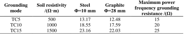
TC5, TC10 and TC15 are grounded by round steel with diameter of 10 mm in practical engineering. The grounding resistance of steel with diameter of 10 mm and graphite grounding material with diameter of 28 mm under three grounding modes is analyzed and compared, as shown in Table 5.
Table 5. Three grounding types of grounding resistance.
Grounding mode Soil resistivity /(Ω·m) Steel Φ=10 mm Graphite Φ=28 mm Maximum power frequency grounding resistance /(Ω)
TC5 500 13.17 12.48 15
TC10 1000 18.55 17.59 20
TC15 1500 23.16 22.03 25
It can be seen that the power frequency grounding resistance of graphite grounding device is less than the maximum power frequency grounding resistance, which meets the requirements, and the grounding resistance of graphite grounding device with diameter of 28 mm is smaller than that of steel grounding device with diameter of 10 mm.
Grounding Resistance at Different Frequencies
[image:4.595.113.485.553.623.2]0 1 2 3 4 5 6 7
[image:5.595.194.395.81.247.2]x 106 12 14 16 18 20 22 24 26 28 30 Frequency(Hz) R es is ta nc e( Ω ) copper 10mm steel 10mm graphite 10mm graphite 22mm graphite 28mm
Figure 5. Grounding resistance of three grounding materials at different frequencies.
It can be obtained that the grounding resistance of the three materials becomes larger as the frequency increases. When the diameter is the same, the grounding resistance of the steel is larger than that of the other two materials. When the frequency is the same, the larger the diameter of the graphite grounding device, the smaller the grounding resistance. As the frequency increases, the grounding resistance of the graphite grounding device rises less than steel and copper grounding devices.
Tower Graphite Grounding Device Lightning Resistance Level
Lightning Level Calculation Model
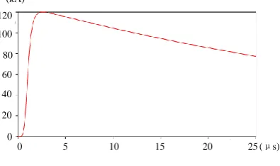
Lightning Current Model. In this paper, the Heidler model [15] is used, and the waveform is 2.6/50 μs. Its waveform is shown in Figure 6.
5 10 15 20 25
0 0
(μs) 20 40 60 80 100 120 (kA)
Figure 6. Lightning current waveform.
Tower Model. In this paper, the multi-wave impedance tower model of Japanese scholar Hara is used. When the lightning wave propagates along the tower, the height of the tower and the size of the tower are the main factors affecting the inductance and capacitance. The multi-wave impedance model considers the influence of these factors, and takes different wave impedances for different parts of the tower [16], and divides the tower wave impedance into three parts: the main body, the pillar and the crossarm.
The main part of each floor of the tower:
60 ln2 2 2
ek k Tk
r h
Z (1)
In the formula 1/8
1/3 2/3
1/3 2/3
3/42 1,2,3,4
ek Tk B Tk B
r r r R R ,k
[image:5.595.213.411.467.584.2]tower;RB is the distance between the bottom pillars.
Wave impedance of each strut:
TK LK Z
Z 9 (2) Cross-wave impedance:
Ak k Ak
r h
Z 60ln2 (3)
In the formula hk is the height of the main body of the tower;rAk is the equivalent radius, taking
1/4 of the length of the joint between the cross arm and the main material.
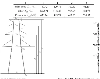
In this paper, the 220kV SZ1C6 tower is used for simulation. The structure of the tower is shown in Figure 7. The calculated wave impedance of each part of the tower is shown in Table 6. The simulation model of the tower established in ATP-EMTP is shown in Fig. 8.
Table 6. Tower impedance.
k 1 2 3 4
main body ZTK /(Ω) 140.42 129.16 107.33 91.19
pillar ZLK/(Ω) 1263.74 1162.43 965.99 820.73
Cross arm ZAK/ (Ω) 476.24 463.78 412.95 396.53
RT1 rT1
rB
h4
rT2
rT3
rT4
RT2
RT3
RT4
RB
h3
h2
h1
[image:6.595.89.478.292.600.2]
Figure 7. Tower structure. Figure 8. ATP-EMTP Tower Simulation Model.
Figure 9. Line parameters.
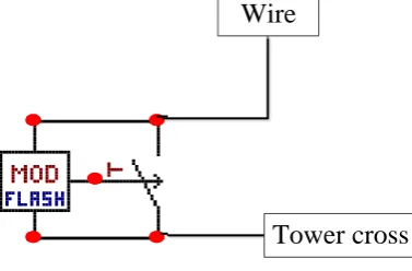
Insulator Flashover Model. In this paper, the definition method is used to judge whether the insulator flashes. The insulator flashover model in ATP-EMTP is shown in Fig. 10.
导线
杆塔横担
Wire
Tower cross
Figure 10. Insulator flashover model.
The insulator flashover model is composed of a controllable switch and a MODELS module. According to the definition method, the insulator does not flash under normal conditions, and the controllable switch is set to the off state at this time. Only when the voltage across the insulator string is higher than U50% of the insulator, the insulator flashes, the controllable switch is set to the closed state, and the insulator string is turned on. The lightning impulse flashover voltage is set to 1200 kV during simulation.
Grounding Resistance Model. The grounding device is shown in Figure 1. The grounding material is steel and graphite, respectively. The rectangular grounding grid is 12.5 m long and 9.5 m wide, and the four-angle ray is extended by 32 m. The grounding device has a buried depth of 0.8 m. The grounding resistance of the graphite grounding device is 12.80 Ω, and the grounding resistance of the round steel grounding device is 13.58 Ω.
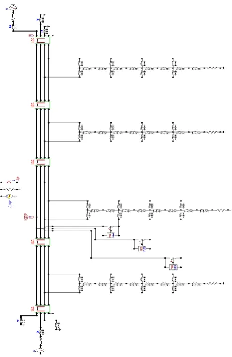
Lightning Resistance Level Simulation of Counterattack
[image:7.595.221.410.241.365.2]Figure 11. Simulation calculation model.
The output of TACS module represents the state of the insulator. When the output is 0, the insulator does not flashover, and continues to increase the amplitude of lightning current. When the output is 1, the insulator flashover occurs. At this time, the lightning current value is defined as the lightning resistance level of the line, indicating the critical value of the insulator flashover.
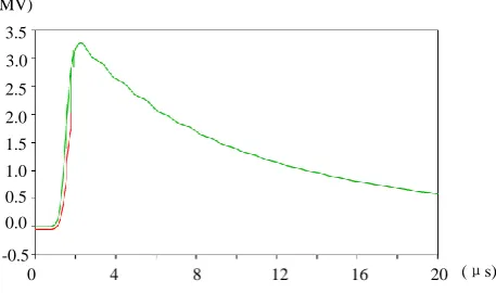
When using round steel grounding device, lightning strikes transmission line towers to make insulators flashover, the voltage at both ends of insulators is shown in Fig. 12. The simulation results show that the lightning resistance level of round steel grounding device is 103.353kA. When using graphite grounding device, lightning strikes transmission line towers to make insulators flashover, the voltage at both ends of insulators is shown in Fig. 13. The simulation results show that the lightning resistance level of graphite grounding device is 108.275kA. The lightning resistance level of the line with graphite grounding device is higher than that of the line with steel grounding device.
0 4 8 12 16 20 (μs)
-1 1 3 5 7 11
9 13 (MV)
[image:8.595.185.410.621.749.2]0 4 8 12 16 20 (μs) -0.5
0.0 0.5 1.0 1.5 2.5 2.0 3.5 (MV)
[image:9.595.184.413.76.211.2]3.0
Figure 13. Voltage at both ends of insulator flashover using graphite grounding device.
Conclusion
In this paper, the model of transmission line tower and its grounding device is established, the power frequency grounding resistance of grounding device is simulated and analyzed, and the lightning resistance level of lightning struck tower with different material grounding device is simulated and calculated. The conclusions are as follows:
(1) Grounding resistance of grounding devices with different materials increases with the increase of soil resistivity. When the diameter is the same, the grounding resistance of graphite is larger than that of copper and steel grounding devices because of its high resistivity. When the diameter increases to 28 mm, the grounding resistance is smaller than that of 10 mm copper and steel.
(2) Grounding resistance of grounding devices with different materials increases with the increase of frequency. In terms of rising trend, graphite grounding devices are slightly smaller than round steel and copper grounding devices when the frequency is greater than 10 kHz.
(3) When the grounding device is box-ray type, the lightning resistance level of 220 kV transmission line lightning tower is obtained by simulation calculation. The lightning resistance level of graphite grounding device with diameter of 28 mm is 108.275 kA, and that of steel grounding device with diameter of 10 mm is 103.353 kA. It can verify that the lightning protection performance of graphite grounding device meets the requirements.
References
[1] Gan, Y.; Zou J.; Zhang C.; Huang D.; Jin X. The Application of Flexible Graphite Composite Electrical Grounding Material in Mountain Grounding Grid. Science Technology and Engineering. 2017, 17(10): 198-201
[2] Xu C. and Hu X. Investigation of anti-corrosive metallic materialfor earthing grid. Power Syst. Technol., 2003(08):77-79.
[3] Tullmin M. and Roberge P. R. Corrosion of metallic materials. IEEETrans. Rel., vol. 44, no. 2, pp. 271–278, Jun. 1995.
[4] B. C. Syrett, J. A. Gorman, M. L. Arey, G. H. Koch, and G. A. Jacobson, Cost of corrosion in the electric power industry. Mater.Perform.,vol.41,no. 3, pp. 18-22, Feb. 2002.
[5] Hu Y.; Ruan J.; Gong R.; Liu Z.; Wu Y.; Wen W. Flexible Graphite Composite Electrical Grounding Material and Its Application in Tower Grounding Grid of Power Transmission System. Power System Technology. 2014, 38(10): 2851-2857.
Performance of Transmission Lines with Multi-circuits on the Same Tower. High Voltage Engineering. 2011, 37(12):3113-3119.
[8] Ye W. Study on the earthing system in overhead transmission line. North China Electric Power University. 2016.
[9] Hu Y.; Ruan J.; Xiao W.; Zhan Q.; Huang D.; Wang X. Study onflexible graphite composite material for electrical grounding and its correlation experimentations. High Voltage Eng. 2016,42(06):1879-1889.
[10] Zhang X. Research on Modeling of Transmission Tower and Overvoltage Distribution under Lighting. North China Electric Power University. 2014.
[11] Zhang Y. High voltage technology. 2nd ed. Beijing: China Electric Power Press, 2007.
[12] Su F.; Li J. Discussion for grounding re-sistance reducing methods. Journal of Electric Power Science and Technology. 2007, 22(2): 84-88.
[13] He J.; Zeng R.; Zhang B. Effectivity of Slanting Grounding Electrode on Improving Grounding Grid Performance. Shaanxi Electric Power. 2008, 36(3): 1-4
[14] Luo Z.; He J.; Zeng R.; et al. Appli-cation of blasting grounding technology in reducing grounding resistance of tower grounding device. National Grid Neutral Grounding Method and Grounding Technology Symposium Proceedings. 2005: 51-54
[15] Chen Y, Liu S, Wu X, et al. A new kind of lightning channel-base current function. International Sym-posium on Electromagnetic Compatibility. IEEE, 2002: 304-307.