http://dx.doi.org/10.4236/epe.2016.84020
Optimisation of Electrical Distribution
System by Using Solar Thermal Powered
Systems and Its Impact on Electrical
Distribution Feeders
Punnaiah Veeraboina1, G. Yesuratnam21Department of Electrical Engineering, Centre for DNA Fingerprinting and Diagnostics (CDFD), Hyderabad, India 2Department of Electrical Engineering, Osmania University, Hyderabad, India
Received 11 February 2016; accepted 26 April 2016; published 29 April 2016
Copyright © 2016 by authors and Scientific Research Publishing Inc.
This work is licensed under the Creative Commons Attribution International License (CC BY). http://creativecommons.org/licenses/by/4.0/
Abstract
In this research, the performance of the solar thermal powered systems (STPS) is analyzed with different models (without inserts, with inserts and with Nano fluids with different concentrations) and its impact on the Electric load in a residential/Institutional Electrical Distribution system. For this purpose, the electrical and solar thermal water heater is tested and validated. Solar thermal powered systems and its impact on the Institutional electrical distribution feeders are tested and compared with the energy efficiency (EE) and cost optimization. The goal of this paper is to ana-lyze the impact of solar thermal energy on electrical energy consumption in the electrical distri-bution feeder level. The electrical system cost and energy consumptions are tabulated and ob-served that there is a considerable savings.
Keywords
Solar Thermal Power Systems, Electrical Distribution Feeder, Energy Consumption, Automatic Power Factor Correction, Electrical Heaters
1. Introduction
con-sidered the second most energy-intensive activity which accounts for approximately 15% of a home’s energy consumption, after HVAC [1]. This fraction could be as high as 30% for residents in winter dominated parts of the world [2]. Solar thermal water heating systems which utilize solar energy to produce hot water can be easily retrofitted into existing electric/gas water heating systems. Solar domestic hot water systems have been widely adopted since they use solar radiation which is free of cost, despite the changes that need to be incorporated to existing systems—such as installation of solar collectors, preheat tanks, internal or external heat exchangers, and circulation control and piping systems [3][4]. B. S. Swanson and J. H. Fletcher [5] investigate the effects of so-lar thermal water heaters (includes the integral collector storage and active drain-back open loop systems) on peak demand.
Generally, a residential electric water heater with a tank for hot water storage is set to heat water at the outlet to a setting point of value Tset, with a Tdelta dead band [6][7]. As soon as hot water is drawn, an equal amount of cold water replenishes the tank at the same flow rate. When the mixed water temperature at the outlet drops be-low the be-lower bound, i.e. Ttank < Tset + Tdelta, the heating elements are turned on to work at rated power till the outlet hot water temperature attains the set point value, i.e. Tset + Tdelta. Water heaters with storage tanks are not free of the standby loss, unlike the tank less water heaters. The heating elements are turned off unless the outlet temperature is not within the range of the dead band, i.e. Tset − Tdelta ≤ Ttank ≤ Tset + Tdelta.
Solar water heating systems are in high demand. Typically, 30% - 40% of a family’s electricity bill is devoted to devoted water. Sun Heat’s system can save the individual family from 70% to 90% of the total amount spent on the Electricity used for heating water. The system generally meets all of the summer time heating needs. During times of decreased sunlight, the system will preheat the water then bring it up to temperature by the conventional water heating system already in place.
For the flat plate collectors, glass panes play an important role in auxiliary electric energy consumption. Flat plate collectors with two glass panes save about 10% - 15% auxiliary electrical energy compared to those with no glass panes and about 3% - 5% energy saving compared to collectors with one glass pane. This is because there are reduced wind convective losses with glass panes. However, there are also transmittance losses from glass panes and there are upper limits on how many glass panes can be used.
The present research is focused on optimization of electrical distribution system (i.e., to reduce the electrical materials used in the system) by using the enhanced solar water heating system (SWHS) and its impact on the electrical distribution feeders. The main purpose is to reduce the Electrical energy consumption and system rat-ings (i.e., transformer size, cable sizes, MCB’s and feeder sizes).
2. Autoclaves
Autoclaving is one of the techniques used in moist heat sterilisation. All R&D organisations and other hospitals requiring their tools to be sterilized need autoclaves. Inlet water to the Autoclaves is normal raw water which is having a temperature between 20˚C - 26˚C depending upon the season. The operational temperature for the Autoclave is 121˚C. There is huge gap between the inlet temperature to the Autoclaves and required for opera-tion. By using the different technics, the experiments are carryout on the Solar flat plate collectors with different models (with inserts, without inserts & by using Nano-fluids) to enhance the output temperature at 90˚C. Con-siderable energy is saved in this system by using solar heated water than the conventional Electrical water heat-ers. The savings are not only the Electrical Energy savings but also the savings on the SITC (Supply, Installation, Testing and Commissioning) of Electrical Installations (Electrical Distribution System). The principle behind the working of an Autoclave is that-The higher the pressure created inside the autoclave, the higher would be the attainable temperature inside it.
The boiling point of water at normal atmospheric pressure is 100˚C. when the free-flowing steam at a tem-perature of 100˚C is subjected under pressure of 1 atmosphere above the sea-level pressure i.e., 15 lbs pressure per sq. inch, the temperature inside the autoclave happens to rise up to 121˚C, which is an usual and common parameters employed in the moist heat sterilisation.
volume, high-throughput medical-grade autoclaves can be.
2.1. Mode of Action/Principle of Moist Heat Sterilization
Moist heat destroys microorganisms by the irreversible denaturation of enzymes and structural proteins. The temperature at which denaturation occurs varies inversely with the amount of water present. Sterilization in saturated steam thus requires precise control of time, temperature, and pressure.
Pressure serves as a means to obtain the high temperatures necessary to quickly kill microorganisms. Specific temperatures must be obtained to ensure the microbicidal activity. Minimum sterilization time should be meas-ured from the moment when all the materials to be sterilized have reached the required temperature throughout.
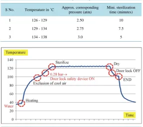
Most of the manufactures recommends the sterilization process in an autoclave are 15 min. at 121˚C and pressure at 2 atm. Table 1 represents the different combinations of temperature, pressure and time. Control and monitor the process is purely based on the temperature and pressure settings to obtain the required steam tem-perature.
Sterilization may be carried out some time even below at 121˚C shown in Figure 1, it’s mostly depends upon the pressure and temperature during the sterilisation.
Steam held at elevated temperature and pressure for time is used to transfer moist heat. Steam has much greater heat transfer than boiling water, −80 calories to boil water, 540 calories to produce steam. Heat acts to denature proteins, effectively killing all cells present.
The steam of the autoclave shown above has been provided from a solar flat plate collector which was stored in a thermal storage system. The required temperature for the Autoclave system is 121˚C. Normally the solar water heating system is designed for 60˚C. But by using the different technics (with inserts and with Nano-fluids) the temperature of the solar flat plat collector is enhanced from 60˚C - 90˚C.
Hospitals, R&D labs and other regional health centres can greatly benefit from using solar Autoclaves. Rural Primary Health Clinics where Electricity is not available to generate steam could benefit from solar Autoclaves.
2.2. Impact on Solar thermal Autoclaves on Electrical Distribution Load
[image:3.595.170.458.455.711.2]Impact on Solar thermal Autoclaves on Electrical Distribution Load in Institutional Building @60˚C and its cost analysis at 500 kVA level is shown in Table 2.
Table 1. Different combinations of temperature, pressure and time.
S No. Temperature in ˚C Approx. corresponding pressure (atm) Mini. sterilization time (minutes)
1 126 - 129 2.50 10
2 129 - 134 2.75 7.5
3 134 - 138 3.0 5
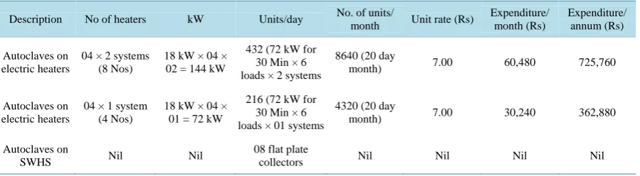
Table 2. Electrical load and the cost analysis of solar autoclaves.
Description No of heaters kW Units/day No. of units/
month Unit rate (Rs)
Expenditure/ month (Rs) Expenditure/ annum (Rs) Autoclaves on electric heaters
04 × 2 systems (8 Nos)
18 kW × 04 × 02 = 144 kW
432 (72 kW for 30 Min × 6 loads × 2 systems
8640 (20 day
month) 7.00 60,480 725,760
Autoclaves on electric heaters
04 × 1 system (4 Nos)
18 kW × 04 × 01 = 72 kW
216 (72 kW for 30 Min × 6 loads × 01 systems
4320 (20 day
month) 7.00 30,240 362,880
Autoclaves on
SWHS Nil Nil
08 flat plate
collectors Nil Nil Nil Nil
Capacity of the Autoclave is 72 kW. Each Electrical Element is 18 kW. Number of Electrical elements is 04 Nos.
So, total capacity of the Autoclave is 18 kW × 04 Nos = 72 kW. Electrical Power Consumption/day:
18 kW × 04 Nos × 30 min (0.5 Hrs) = 36 kWh.
Daily number of loads is 06 times, Number of Autoclaves is 02 Nos.
So, the total Electrical Energy consumption/day = 36 kW × 06 Nors × 02 systems = 432 kWh. Number of units per month:
Normally R&D labs will work only 05 day week, so, the number days per month = 20 days. Number of units consumed per month = 432 kWh × 20 days = 8640 units.
As per Cat-II tariff, per unit charge is Rs 7 per unit.
So, the Electrical Power consumption per year is 8640 units × Rs 7 = Rs 60,480. Electrical Power Consumption per year:
Rs 60,480 × 12 Months = Rs 725,760.
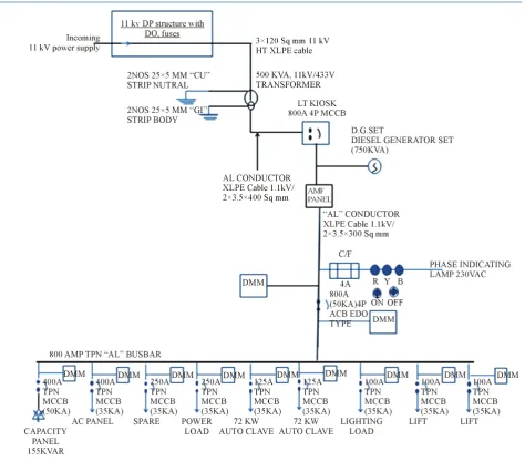
Figure 2 represents the SLD (Single Line Diagram) and Bill of Materials (BoQ) of 500 kVA Electrical
Dis-tribution system at feeder level.
Designed capacity of the Electrical Distribution system is 500 kVA:
Without using the solar water heating system, the required temperature of the Autoclaves is around 121˚C. To increase the temperature at 121˚C, 144 kW (18 kW × 8 Nos) of Electrical Heaters are used. The capacity of the Electrical Load is 144 kW at 0.98 P.F (say 150 kVA).
The Electrical Distribution system, one of the feeder (250 Amps, TPN MCCB-Power Load) is connected to the domestic water heating load, the total Electrical load of 40 rooms of each 2.5 kW capacity Electrical heaters are connected.
There for the total capacity of the domestic heating Electrical load = 2.5 kW × 40 rooms = 100 kW = 102 kVA (100 kW at 0.98 P.F). The load reduction is 150 kVA + 102 kVA = 252 kVA, the other Distribution loads are 248 kVA.
Based on the above Electrical loads the recommended size of Transformer is 500 kVA and its cost analysis is shown in Table 3.
2.3. Automatic Power Factor Correction (With Thyristor Switched)
Techniques can be applied to the industries, power systems and also households to make them stable and due to that the system becomes stable and efficiency of the system as well as the apparatus increases. The use of mi-crocontroller reduces the costs. Automatic Power factor correction (APFC) device reads the power factor from line voltage and line current, calculating the compensation requirement switch on different banks. Improving the power factor of an installation requires a bank of capacitors which acts as a source of reactive energy. This ar-rangement is said to provide reactive energy compensation.
Figure 2. Single line diagram of the electrical distribution system for 500 kVA transformer level.
Table 3. Cost analysis of Electrical Distribution systems at 500 kVA Transformer level.
S No. Description Qty UoM Rate (Rs) Total system cost (Rs)
1 HT cable: supply of 11 kV 3C × 120 Sq. mm HT
XLPE armoured Cable. 50 Mtr 1100 55,000
2 LT cables: supply of 3.5c × 400 Sq. mm XLPE insulated,
1.1 kV grade armoured aluminium cable. 100 Mtr 1800 180,000
3 HT metering panel (11kV) 1 Nos 332,000 332,000
4 500 KVA O/D TRANSFORMER (OIL FILLED) 1 each 720,000 720,000
5 APFC PANEL (Thyristor Switched) 1 No 459,400 459,400
6 LT KIOSK 800A TPN 4P 50KA EOD type ACB 1 No 288,000 288,000
7
Main LT Panel: I/C: 800A 4 pole EDO type ACB (50 KA)-1 No. O/G (400 A TPN MCCB-2 Nos,
250 A-2 Nos, 125 A-2 Nos, 100 A-3 Nos)
1 No 644,000 644,000
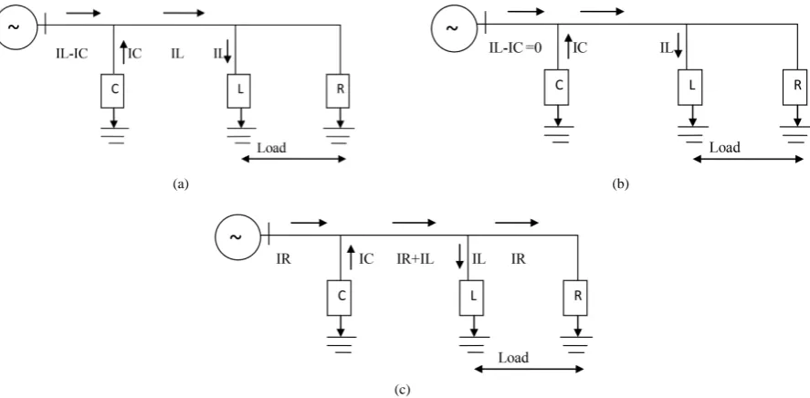
[image:5.595.82.539.532.723.2]reactive current (IL). The two components flowing through the same path will cancel each other, such that if the capacitor bank is sufficiently large and Ic = IL, there will be no reactive current flow in the system upstream of the capacitors. This is indicated in Figure 3 which shows the flow of the reactive components of current only.
In Figure 3: R is active-power elements of the load, L is (inductive) reactive-power elements of the load, and C is (capacitive) reactive-power elements of the power-factor correction equipment (i.e. capacitors).
kVAR required for transformer compensation:
Transformer Required Kva
≤315 kVA T.C = 5% of KVA
315 kVA to 1000 kVA = 6% of KVA
≥1000 kVA = 8% of KVA
Calculation of required capacitor:
Fixed compensation of the 500 kVA Transformer is (500 kVA × 6%) = 30 kVAR. Suppose actual P.F is 0.8, required P.F is 0.98 and total connected load is 354 KVA.
kW = 354 × 0.8 = 283.20. Required capacitance = 283.20 × Multiplying Factor = 283.20 × 0.547 (from Table 4 to find Value according to P.F 0.8 to P.F of 0.98) = 155.00 kVAR.
Total capacity of the APFC panel = Fixed compensation + Variable compensation i.e., 155 kVAR + 30 kVAR = 185 kVAR (available rating).
The capacity of the APFC panel in Figure 4 shows 155 kVAR capacity rest is fixed compensation. Load Re-duction by STWH at 11 kV Electrical Distribution System is represented in Table 5.
2.4. Impact on Solar Thermal Autoclaves on Electrical Distribution Load at 315 kVA
Impact on Solar Thermal Autoclaves on Electrical Distribution Load in Institutional Building @60˚C and its cost analysis at 315 kVA level.
Designed capacity of the electrical distribution system is 315 kVA:
With using the solar water heating system, the hot water output is at 60˚C, but required temperature is around 121˚C. To increase the temperature from 60˚C - 121˚C, 18 kW × 4 Nos of Electrical Heater are used. The capac-ity of the Electrical Load is 75 kVA (72 kW at P.F 0.95).
(a) (b)
[image:6.595.92.536.477.695.2](c)
Figure 4. Single line diagram of the electrical distribution system for 315 kVA transformer level.
Table 4. Table for finding the required multiplication factor (P.F from 0.6 to unity) [8].
0.9 0.91 0.92 0.93 0.94 0.95 0.96 0.97 0.98 0.99 1
0.6 0.849 0.878 0.907 0.938 0.970 1.005 1.042 1.083 1.130 1.191 1.333
0.7 0.536 0.565 0.594 0.625 0.657 0.692 0.729 0.770 0.817 0.878 1.020
0.8 0.266 0.294 0.324 0.355 0.387 0.421 0.458 0.499 0.547 0.608 0.750
0.85 0.135 0.164 0.194 0.225 0.257 0.291 0.328 0.369 0.417 0.477 0.620
0.9 0.029 0.058 0.089 0.121 0.156 0.193 0.234 0.281 0.342 0.484
0.91 0.030 0.060 0.093 0.127 0.164 0.205 0.253 0.313 0.456
0.92 0.031 0.063 0.097 0.134 0.175 0.223 0.284 0.426
0.93 0.032 0.067 0.104 0.145 0.192 0.253 0.395
0.94 0.034 0.071 0.112 0.160 0.220 0.363
[image:7.595.89.539.530.721.2]The Electrical Distribution system, one of the feeder (250 Amps, TPN MCCB-Power Load feeder) is con-nected to the domestic water heating load, the total Electrical load of 40 rooms of each 2.5 kW capacity Electri-cal heaters are connected,
There for the total capacity of the domestic heating Electrical load is 102 kVA (100kW at 0.98 P.F). The load reduction is 177 kVA (say 180 kVA).
Required size of Transformer after load reduction i.e., 500 kVA - 180 kVA = 320 kVA Recommended size of Transformer is 315 kVA and its cost analysis is shown in Table 6.
2.5. Calculation of Required Capacitor
Fixed compensation of the 315 kVA Transformer is (315 kVA × 5%) =15.75 kVAR. Suppose actual P.F is 0.8, required P.F is 0.98 and total load is 282 KVA.
kW = 282 × 0.8 = 225.60, Required capacitance = 123.40 kVAR.
Total capacity of the APFC panel is 139 kVAR (i.e., fixed compensation + variable compensation). The ca-pacity of the APFC panel in Figure 5 shows 139 kVAR capacity rest is fixed compensation.
2.6. Impact on Solar Thermal Autoclaves on Electrical Distribution Load in Institutional Building @60˚C and Its Cost Analysis Shown in Table 7 at 250 kVA Level
[image:8.595.88.539.363.483.2]Designed capacity of the Electrical Distribution system is 500 kVA. With using the solar water heating system with inserts (twisted inserts with Nano fluids), the hot water output is at 90˚C, but required temperature is around 121˚C.
Table 5. Autoclave and its load reduction by STWH systems.
Description Electrical load (Auto claves) kVA
Electrical load (DWHS) kVA
Load reduction kVA
Recommended
TFR sizes in kVA @60˚C @90˚C
Conventional Electrical
System. 150 105 Nil 500 Nil Nil
Load reduction by STWH’s-
with inserts @90˚C 75 105 180 315 Up to 60˚C for DWHS
With twisted inserts
Load reduction by STWH’s with Nano fluids and twisted
tape inserts@90˚C 19 105 236 250
Up to 60˚C for DWHS
With inserts and Nano fluids
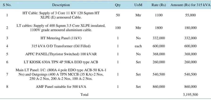
Table 6. Cost analysis of electrical distribution systems at 315 kVA TFR level.
S No. Description Qty UoM Rate (Rs) Amount (Rs) for 315 kVA
1 HT Cable: Supply of 3 Core 11 KV 120 Sqmm HT
XLPE (E) armoured Cable. 50 Mtr 1100 55,000
2 LT cables: Supply of 400 Sqmm 3.5 Core XLPE insulated,
1100V grade armoured aluminium cable. 100 Mtr 1800 180,000
3 HT Metering Panel (11kV) 1 No 332,000 332,000
4 315 kVA O/D Transformer (Oil Filled) 1 each 600,000 600,000
5 APFC PANEL(Thyristor Switched) 100 kVAR 1 No 368,000 368,000
6 LT KIOSK 630A TPN 4P 50KA EOD type ACB 1 Set 260,000 260,000
7
Main LT Panel: I/C: (800A 4 pole EDO type ACB-50 KA-1 No) and Outgoings (400 A TPN MCCB (35 KA)-2 Nos,
250 A-2 Nos, 200 A-2 Nos, 100 A-2 Nos.
1 Set 540,500 540,500
8 AMF Panel suitable for 500 kVA 1 Set 860,000 860,000
[image:8.595.88.536.509.722.2]To increase the temperature from 90˚C - 121˚C, 18 kW × 1 No of Electrical Heater are used. The capacity of the Electrical Load is 19 kVA (18 kW at P.F 0.95).
The load reduction is 126 kW (133 kVA, P.F as 0.95).
The Electrical Distribution system, one of the feeder (250 Amps, TPN MCCB-Power Load feeder) is con-nected to the domestic water heating load, the total Electrical load of 40 rooms of each 2.5 kW capacity Electri-cal heaters are connected,
There for the total capacity of the domestic heating Electrical load = 102 kVA (100 kW at 0.98 P.F). Load reduction is 235 kVA.
The required size of Transformer after load reduction i.e., 500 kVA − 235 kVA= 265 kVA. So, recommended size of Transformer is 250 kVA, the cost analysis of the system is represents in Table 8.
Calculation of required capacitor:
Fixed compensation of the 500 kVA Transformer is (250 kVA × 5%) = 12.5 kVAR. Actual P.F is 0.8, required P.F is 0.98 and total load is 210 KVA.
kW = 210 × 0.8 = 168,
Required capacitor = kW × Multiplying Factor = 168 × Multiplying Factor= 168 × 0.547 (from table to find Value according to P.F 0.8 to P.F of 0.98) = 92 kVAR.
Total capacity of the APFC panel is 105 kVAR (i.e., fixed compensation + variable compensation). The capacity of the APFC panel in Figure 5 shows 80 kVAR capacity rest is fixed compensation.
2.7. Methodology
[image:9.595.89.538.408.471.2]In the first stage of the study, the hot water temperature is enhanced to 90˚C by using inserts into the solar flat plate collector fins. The enhanced water is fed to the Autoclaves for generation of the steam at 121˚C. Informa-tion such as current (Amps), voltage (Voltage) and power (kW) was collected directly from the nameplate af-fixed on the Autoclave.
Table 7. Impact of solar thermal systems on electrical distribution system at 90˚C.
Description Geysers No of kW Units/day/ geyser No. of units Unit rate (Rs) Cost/day (Rs) Cost/month (Rs) Cost/annum (Rs)
Electric Geyser (2.5 kW) 40 100 11 440 7.00 3080 92,400 1,108,800
SWHS Nil Nil 08 FPC Nil Nil Nil Nil Nil
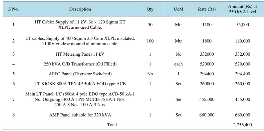
Table 8. Cost analysis of electrical distribution systems at 250 kVA TFR level.
S No. Description Qty UoM Rate (Rs) Amount (Rs) at
250 kVA level
1 HT Cable: Supply of 11 kV, 3c × 120 Sqmm HT
XLPE armoured Cable. 50 Mtr 1100 55,000
2 LT cables: Supply of 400 Sqmm 3.5 Core XLPE insulated,
1100V grade armoured aluminium cable. 100 Mtr 1800 180,000
3 HT Metering Panel 11 kV 1 No 332000 332,000
4 250 kVA O/D Transformer (Oil Filled) 1 each 520000 520,000
5 APFC Panel (Thyristor Switched) No 1 294400 294,400
6 LT KIOSK 800A TPN 4P 50KA EOD type ACB 1 Set 260000 260,000
7
Main LT Panel: I/C (800A 4 pole EDO type ACB-50 kA-1 No, Outgoing (400 A TPN MCCB-35 kA-1 Nos,
250 A-3 Nos, 100 A-3 Nos.
1 Set 455,000 455,000
8 AMF Panel suitable for 320 kVA 1 Set 660,000 660,000
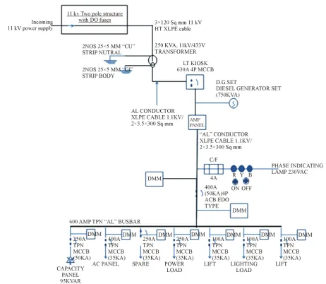
[image:9.595.83.538.496.722.2]Figure 5. Single Line Diagram (SLD) of the electrical distribution system for 250 kVA transformer level.
After measuring the power consumption of the Autoclaves without solar hot water, the capacity of the Trans-former was estimated. Then by using the solar hot water at 90˚C was estimated. The cost savings of the system was calculated with Autoclave Electrical Heaters and without Electrical heaters for 60˚C and 90˚C. For the equipment which was tested, the weekly power consumption (kWh/week) can be obtained using the same equa-tion. But instead of using the nameplate power rating, the actual measured power rating was used. According to the calculations, the cost of the Transformer changes from rating to rating. In this context, it is important to note that this rate of cost of higher capacity Transformer and its associated feeders is less than smaller capacities and also considerable Electrical Energy savings are noted with and without Solar Hot water systems.
3. Conclusions
The electrical energy consumption and its cost analysis have been calculated for systems and observed that there is a considerable savings by using the solar hot water at 90˚C. The use of Al2O3 nanoparticles as the dispersed phase in water can significantly enhance the convective heat transfer in the transition flow, and the enhancement increases with increase in particle concentration and further can be increased by using the different types of in-serts. The temperature of the outlet get at 90˚C and the same has been connected to the Autoclave.
at 90˚C by using different methods to enhance the temperature. Average weekly power consumption, capacities and cost of operation were analysed. By using the enhanced methods, the cost of the electrical distribution net-work and its capacities are optimised at feeder level.
References
[1] Paull, L., Li, H. and Chang, L.C. (2010) A Novel Domestic Electric Water Heater Model for a Multi-Objective De-mand Side Management Program. Electric Power Systems Research, 80, 1446-1451.
http://dx.doi.org/10.1016/j.epsr.2010.06.013
[2] Knudsen, S. (2002) Consumers’ Influence on the Thermal Performance of Small SDHW Systems-Theoretical Investi-gations. Solar Energy, 73, 33-42. http://dx.doi.org/10.1016/S0038-092X(02)00018-X
[3] Kalogirou, S.A. (2004) Solar Thermal Collectors and Applications. Progress in Energy and Combustion Science, 30, 231-295. http://dx.doi.org/10.1016/j.pecs.2004.02.001
[4] Zhang, R., Zhu, H., Wen, H. and Li, M. (1993) Performance Analysis of a Solar Glass Tube Collector. Renewable En-ergy, 3, 877-883.
[5] Swanson, B.S. and Fletcher, J.H. (2008) Analysis of Solar Thermal Water Heaters on Peak Demand. Proceedings of ECTC 2008, 2008 ASME Technical Conference, 3-4 October 2008.
[6] http://www.energysavers.gov/tips/water heating.cfm
[7] Taylor, Z.T., Gowri, K. and Katipamula, S (2008) GridLAB-D Technical Support Document: Residential End-Use Module Version 1.0.
![Table 4. Table for finding the required multiplication factor (P.F from 0.6 to unity) [8]](https://thumb-us.123doks.com/thumbv2/123dok_us/7948795.751783/7.595.68.544.78.483/table-table-finding-required-multiplication-factor-p-unity.webp)